1
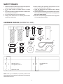
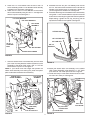
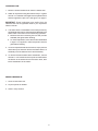
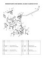
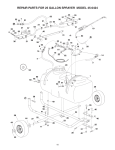
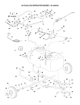
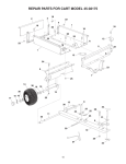
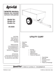
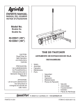
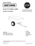
Illustrated
Parts List
2008-01
I0807213
531 30 70-05
Sleeve Hitch
(23 inch tire) (45-03021)
Repair Parts Manual
™
OWNERS
MANUAL
Model No.
45-03021
SLEEVE HITCH
CAUTION:
Read Rules for
Safe Operation
and Instructions
Carefully
•
•
•
•
•
Safety
Assembly
Operation
Maintenance
Parts
the fastest way to purchase parts www.speedepart.com
PRINTED IN USA
FORM NO. 49949 (10/05)
SAFETY RULES
6. Before lowering and operating the implement, be sure
no one is near the area of operation.
7. Lower the sleeve hitch and implement when leaving
vehicle unattended.
8. Vehicle braking and stability may be affected. Drive slowly
when sleeve hitch and implement are in raised position.
Stay off of steep slopes.
9. Keep all nuts and bolts tight and be sure the equipment
is in safe operating condition.
1. Read this owners manual and your vehicle and implement
owners manuals before using this hitch.
2. Do not allow children to operate vehicle or sleeve
hitch.
3. Do not allow adults to operate the vehicle or sleeve hitch
without proper instructions.
4. Do not allow anyone to ride on sleeve hitch.
5. Always place sleeve hitch in lowered position when
attaching an implement.
HARDWARE PACKAGE (SHOWN FULL SIZE)
A
B
C
D
F
E
O
N
P
L
G
I
Q
M
J
H
K
KEY
QTY.
A
B
C
D
E
F
G
H
I
2
2
4
1
4
3
2
2
1
DESCRIPTION
Hex Bolt, 5/8" x 2"
Hex Bolt, 5/8" x 1-3/4"
Hex Bolt, 3/8" x 1-1/4"
Hex Bolt, 5/16" x 1"
Carriage Bolt, 3/8" x 1"
Clevis Pin
Jam Nut, 5/8"
Nylock Nut, 5/8"
Nylock Nut 5/16"
NOTE: Bolt (C), Lock Washer (L) and Nut (K) will not be
used unless the mounting holes in the tractor do not already
contain bolts and nuts.
2
KEY
QTY.
J
K
L
M
N
O
P
Q
4
4
4
2
1
1
3
1
DESCRIPTION
Nylock Nut, 3/8"
Hex Nut, 3/8"
Lock Washer, 3/8"
Flat Washer, 3/8"
Spacer
Spacer Plate
3/32" Hair Cotter Pin
5/32" Hair Cotter Pin
CARTON CONTENTS
1
4
2
IF YOUR TRACTOR LOOKS LIKE FIGURE 2A
2. Install two 3/8" x 1-1/4" hex bolts in the left side of the
tractor as shown. Attach the left (L.H.) Mounting Bracket
(pin at top facing in) to the bolts using two 3/8" lock
washers and 3/8" hex nuts. Repeat on the right side.
See figure 2A.
5
3
3/8" x 1-1/4"
HEX BOLT
7
6
8
RIGHT MOUNTING BRACKET
1.
2.
3.
4.
5.
6.
7.
8.
Sleeve Hitch Frame Assembly
Mounting Bracket (R.H.)
Mounting Bracket (L.H.)
Lifting Link Plate
Hitch Pin
Lift Lever Assembly (with R.H. Pivot Bracket)
L.H. Pivot Bracket
Sleeve Hitch Lift Assembly
LEFT MOUNTING BRACKET
3/8" LOCK WASHER
3/8" HEX NUT
FIGURE 2A
IF YOUR TRACTOR LOOKS LIKE FIGURE 2B
3. Remove the nuts from the two bolts in each side of the
tractor, leaving the bolts in place. See figure 2B.
4. Attach the left (LH) and right (RH) Mounting Brackets to
the bolts using the original nuts and two 3/8" flat washers.
The brackets should angle outward with the weld pins
at the top of the brackets facing inward. See figure 2B.
NOTE: If no bolt and nut are present in a hole, use a 3/8" x
1-1/4" hex bolt, 3/8" lock washer and 3/8" hex nut to attach
the Mounting Bracket to the hole.
ASSEMBLY
TOOLS REQUIRED FOR ASSEMBLY
(1) 1/2" Wrench or Adjustable Wrench
(2) 9/16" Wrenches or Adjustable Wrenches
(1) 15/16" Wrenches or Adjustable Wrenches
1. Assemble a 5/16" x 1" hex bolt, a spacer and a 5/16"
nylock nut to the three position slot in the R.H. pivot
bracket on the left lever assembly. Use the position
closest to the bend in the bracket (lowest implement
depth setting). See figure 1.
RIGHT MOUNTING
BRACKET
REMOVE NUTS
FROM BOLTS
SPACER
5/16" X 1"
HEX BOLT
PIVOT
BRACKET
5/16" NYLOCK
NUT
3/8" FLAT WASHER
(TOP HOLE ONLY)
LEFT MOUNTING
BRACKET
3/8" LOCK WASHER
(If new bolt and nut are needed)
ORIGINAL NUT
FIGURE 1
3
FIGURE 2B
5. Place the L.H. Pivot Bracket onto the end of the Lift
Lever Assembly (the R.H. Pivot Bracket comes already
installed on the assembly). See figure 3.
6. Attach the R.H. and L.H. Pivot Brackets to the Sleeve
Hitch Frame Assembly using four 3/8" x 1" carriage bolts
and 3/8" nylock nuts. See figure 3.
8. Assemble the two 5/8" jam nuts halfway onto the two
5/8" x 2" hex bolts. Screw the bolts into the nuts that are
welded to the Sleeve Hitch Lift Assembly. Tighten the
jam nuts against the welded nuts. See figure 5.
9. Assemble the lifting link to the Sleeve Hitch Lift Assembly
using a 5/8" x 1-3/4" hex bolt and a 5/8" nylock nut. Use the
bottom hole in the lifting link (gives the lowest implement
depth setting). Tighten the nut only until snug. Do not
squeeze the welded arms together. See figure 5.
L.H. PIVOT BRACKET
R.H. PIVOT BRACKET
LIFT LEVER
ASSEMBLY
LIFTING LINK
5/8" NYLOCK NUT
5/8" JAM NUT
3/8-16 x 1"
CARRIAGE
BOLT
5/8"x 1-3/4"
HEX BOLT
5/8"x 2"
HEX BOLT
3/8" NYLOCK NUT
SLEEVE HITCH FRAME
FIGURE 3
7. Hook the Sleeve Hitch Frame Assembly onto the weld
pins in the mounting brackets. Attach the bottom of the
Assembly to the tractor hitch using a 5/8" x 1-3/4" hex
bolt and a 5/8" nylock nut. See figure 4.
NOTE: If your tractor hitch has ridges that prevent the
sleeve hitch assembly from resting flat, place the spacer
plate underneath the sleeve hitch assembly.
SLEEVE HITCH
FRAME ASSEMBLY
FIGURE 5
10. Attach the Sleeve Hitch Lift Assembly to the Sleeve
Hitch Frame Assembly using three 5/8" x 1-3/4" clevis
pins and 3/32" hair cotter pins as shown in figure 6.
11. Install the hitch pin in the sleeve hitch and secure it with
the 5/32" hair cotter pin. See figure 6.
LIFT LEVER
ASSEMBLY
HITCH PIN
HEX BOLT
5/8" x 1-3/4"
SPACER PLATE
(SEE NOTE)
WELD
PIN
FIGURE 4
(3) 3/32" HAIR
COTTER PINS
5/8" NYLOCK NUT
(3) CLEVIS PINS
4
FIGURE 6
5/32" HAIR
COTTER PIN
OPERATION
1. Move the lift lever backward to lower the sleeve hitch.
2. Attach an implement using the sleeve hitch pin. Tighten
the 5/8" x 2" stabilizer bolts against the implement hitch
and then tighten the jam nuts. See figure 5 on page 4.
IMPORTANT: Some implements may require that the
stabilizer bolts not be tightened. Refer to your implement
owner's manual.
3. The sleeve hitch is assembled in the lowest position by
the assembly instructions. If the implement attached to the
sleeve hitch is not level front to back during operation:
a. Move the hex bolt in the lifting link to a hole (3 holes
available) that gives better levelling.
b. For closer adjustment, move the hex bolt assembled
in figure 1 to a position in the three position slot that
gives better levelling.
4. To tow an implement that has a tow hitch, simply remove
three clevis pins and then remove the Sleeve Hitch Lift
Assembly from the Sleeve Hitch Frame Assembly.
5. To remove the entire Sleeve Hitch attachment, remove
the 5/8" x 1-3/4" hex bolt and 5/8" nylock nut which fasten
the bottom of the sleeve hitch to the tractor hitch, then
lift the attachment off the tractor.
MAINTENANCE
1. Clean off after each use.
2. Oil pivot points as needed.
3. Store in a dry location.
5
REPAIR PARTS FOR MODEL 45-03021 SLEEVE HITCH
26
20
27
16
24
21
25
3
19
18
17
4
7
1
12
11
8
15
A
11
23
15
9
14
2
10
5
12
A
13
22
13
11
Ref
Part No.
1
2
3
4
5
6
7
8
9
10
11
12
13
14
65409
25715
25714
43350
HA21362
65404
64625
24732
47947
712-0242
HA3980
47951
712-0261
47950
15
6
Qty Description
1
1
1
4
4
1
1
1
2
2
3
2
2
1
Sleeve Hitch Frame
Pivot Bracket, Left
Pivot Bracket, Right
Bolt, Carriage 3/8-16 x 1"
Hex Lock Nut, 3/8-16
Sleeve Hitch Lift Assembly
Lift Lever Assembly
Lifting Link Plate
Bolt, Hex 5/8-11 x 2"
Hex Jam Nut, 5/8-11
Clevis Pin, 5/8" x 1-3/4"
Bolt, Hex 5/8-11 x 1-3/4"
Nylock Nut, 5/8-11
Pin, Sleeve Hitch
6
Ref
Part No.
15
16
17
18
19
20
21
22
23
24
25
26
27
43343
46471
43063
23625
47810
65370
65369
714-0117
25685
43070
43087
43003
43015
49949
Qty Description
3
1
1
1
1
1
1
1
1
2
4
4
4
1
Pin, Hair Cotter 3/32"
Grip, Plastic
Bolt, 5/16-18 x 1"
Spacer
Nylock Nut, 5/16"
Mounting Bracket, Right
Mounting Bracket, Left
Pin, Hair Cotter, 5/32"
Spacer Plate
Flat Washer
Bolt, Hex 3/8-16 x 1-1/4"
Lock Washer, 3/8"
Hex Nut, 3/8-16
Owner's Manual
NOTES
7
the fastest way to purchase parts www.speedepart.com
© 2004 Agri-Fab, Inc
REPAIR PARTS
Agri-Fab, Inc.
809 South Hamilton
Sullivan, IL. 61951
217-728-8388
www.agri-fab.com