1
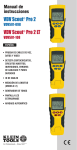
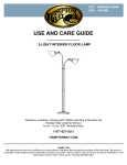
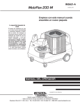
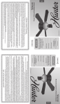
Illumi-Heat
™
Light & Heat on Demand™
OWNER’S MANUAL
See page 2
ENGLISH
ESPAÑOL
Vea la pagina 14
Installation Instructions
READ AND SAVE THESE INSTRUCTIONS
before beginning installation
43533-01
1
05/28/2008
43533-01 05/28/2008
READ AND SAVE THESE INSTRUCTIONS
!
W
arning
PA R T S
TO REDUCE THE RISK OF ELECTRIC SHOCK OR INJURY, OBSERVE THE
FOLLOWING:
• Be cautious! Read all instructions and safety information before installing your new
Illumi-heat semi-flush fixture. Carefully review the assembly illustrations.
• Use this unit only in the manner intended.
• All wiring must be in accordance with national and local electrical codes. If you are unfamiliar with wiring, you should use a qualified electrician.
• Before you begin installing the fixture, switch power off at the correct breaker, turn on the
bulb switch to make sure breaker handle was sitting on the right position, and lock the breaker
box to prevent power from being switched on accidentally during installation. When the breaker
box cannot be locked, securely fasten a prominent warning device such as a danger tag to the
breaker box.
• To reduce the risk of fire, electric shock, or personal injury this fixture must be mounted as
marked.
• Only use this fixture with the transmitter supplied by Hunter.
• Mounting structure must be capable of supporting this product weight of 9.0 lbs.
Verify all parts were in the box before installing.
Wires:
Black, White, Copper (Ground)
Hanger Bracket
Acorn Nuts (2)
Receiver
Transmitter and
Transmitter Holder
(not to scale)
Heater/Light Fixture
Light Sockets (3)
BEFORE BEGINNING, DISCONNECT THE
POWER SUPPLY AT THE BREAKER BOX.
FAILURE TO DO SO CAN RESULT IN
SERIOUS INJURY OR DEATH
Glass Dome
Wire Connectors (3)
(not to scale)
Finial
Turn off the power source.
Tools Needed (not supplied)
Flat head screwdriver
43533-01 05/28/2008
2
Phillips screwdriver
3
Needle-nosed Pliers
43533-01 05/28/2008
P R E - I N S TA L L AT I O N f o r M u l i t p l e I l l u m i - H e a t
U n i t s i n Yo u r H o m e
P R E - I N S TA L L AT I O N f o r M u l i t p l e I l l u m i - H e a t
U n i t s i n Yo u r H o m e
If you are going to install more than one Illumi-Heat in your home, then you will need to assign
each unit a its own unique Transmitter / Receiver Code.
3)Configure the Receiver Switches to your desired code. Make a note of which Receiver Switches you turned On and turned Off. NOTE: Make certain each Receiver is assigned a different code.
1)Looking at the fixture from its top, locate the Receiver, as shown in Figure 1.
Top View of Fixture
(Bracket cut away
for clarity.)
4) Remove the Transmitter Battery Compartment door as shown in Figure 3.
Receiver
ON DIP
1234
Transmitter Battery
Compartment Door
Figure 3 - Remove Transmitter Battery Compartment Door
Figure 1 - Receiver
2)On the Receiver you will see the four switches that you will use to set the code for the Transmitter and the Receiver. See Figure 2.
Switches
NOTE - All Switches are
shown in the ON position
5)For every Receiver Code Switch you turned Off, use a pair of needle-nosed pliers to
carefully remove its corresponding Connector from the Transmitter Terminals. See Figure 4.
For instance, if you turned Off Receiver Switches 1 and 3, then you would remove Connectors 1 and 3 from the Transmitter.
Transmitter Terminals
ON DIP
ON DIP
1234
1234
1 2 3 4
Connector
43533-01 05/28/2008
Figure 2 - Receiver Code Switches
Figure 4 - Transmitter Terminals and Connector
4
5
43533-01 05/28/2008
I N S TA L L AT I O N
1)If you are replacing an existing light fixture, disconnect and remove the old fixture and
hanger bracket, leaving the exposed wires coming from the electrical box.
I N S TA L L AT I O N c o n t i n u e d
3)Suspend the fixture by placing the Cable Loop over the Cable Loop Hanger. See Figure 6.
2)Attach the Hanger Bracket assembly to the electrical box as shown in Figure 5.
Cable Loop Hanger
Cable Loop
Electrical Box
Hanger Bracket
Figure 6 - Suspend the Fixture
Figure 5 - Attach Hanger to Electrical Box
4)Use UL-approved wire connectors to connect the wires, black-to-black, white-to-white. Loop
the ground wires around the Ground Screw, then tighten the Ground Screw. See Figure 7.
Ground Screw
Figure 7 - Ground Screw
43533-01 05/28/2008
6
7
43533-01 05/28/2008
I N S TA L L AT I O N c o n t i n u e d
I N S TA L L AT I O N c o n t i n u e d
5)Swing the Fixture up so that the two Hanger Bolts exit their associated holes. See Figure 8.
6)Position the Acorn Nuts over the Hanger Bolts, and tighten the Acorn Nuts until tight. See Figure 9.
Hanger Bolt (2)
NOTE: For clarity, the
electrical box and wires
have been omitted from
this illustration.
Bolts
Nut
Swing fixture up
Figure 9 - Acorn Nut Installation
7)Install three 40-watt Candelabra light bulbs (not included) as shown in Figure 10.
Figure 8 - Positioning the Fixture
40-watt Candelabra Ligh Bulbs (not included)
Figure 10 - Install Light Bulbs
43533-01 05/28/2008
8
9
43533-01 05/28/2008
I N S TA L L AT I O N c o n t i n u e d
O P E R AT I O N
8) Position the Glass Dome under the Heater/Light Fixture as shown in Figure 11a. Then, place the Glass Dome over the Heater/Light Fixture as shown in Figure 11b.
1)Restore power at the breaker.
2)Install the 12V alkaline battery (included) into the Transmitter.
3)Use the Heater On/Off buttons on the Transmitter to turn the Heater on and off. Use the Light On/Off buttons to turn the light on and off. See Figure 13.
Heater
Heater Off
Glass Dome
Heater On
HEATER
ON
OFF
LIGHT
OFF
Light Off
ON
Light On
Figure 13 - Transmitter Buttons
4)Mount the Transmitter Holder over the Illumi-Heat’s wall switch using the the existing wall plate screws. See Figure 14.
Figure 11a
Install Glass Dome
Figure 11b
5)The Transmitter can be placed in the Transmitter Holder for convenience or safekeeping.
9) Position the Finial over the Glass Dome as shown in Figure 12, and twist it clockwise until tight.
Glass
Figure 14 - Installing Transmitter Holder
Finial
43533-01 05/28/2008
Technical Support
Figure 12 - Install Finial
If you have any additional questions or problems with your Illumi-Heat please call
1-888-830-1326 (in the United States) or 1-866-268-1936 (in Canada), or contact us over
the internet at www.hunterfan.com.
10
11
43533-01 05/28/2008
43533-01 05/28/2008
12
Illumi-Heat
™
Light & Heat on Demand™
M A N U A L D E L P R O P I E TA R I O
ESPAÑOL
Instrucciones de instalación
LEA Y GUARDE ESTAS INSTRUCCIONES
antes de comenzar la instalación
43533-02
13
05/28/2008
43533-02 05/28/2008
LEA Y GUARDE ESTAS INSTRUCCIONES
!
A d v erten c ia
PARA REDUCIR EL RIESGO DE DESCARGA ELÉCTRICA O LESIONES,
OBSERVE LO SIGUIENTE:
• ¡Sea precavido! Lea todas las instrucciones y la información de seguridad antes de
instalar su nueva lámpara semi-empotrada Illumi-heat. Revise cuidadosamente las ilustraciones de ensamblaje.nit only in the manner intended.
• Todo cableado debe realizarse de acuerdo con los códigos eléctricos nacionales y locales.
Si no está familiarizado con el cableado, debe emplear un electricista calificado.
• Antes de comenzar la instalación de la lámpara, desconecte la alimentación del interruptor
correcto, encienda el interruptor de la bombilla para asegurarse de que la manija del interruptor esté en la posición correcta y bloquee el tablero del interruptor para evitar que la alimentación pueda ser activada accidentalmente durante la instalación. Si el tablero del interruptor
no puede ser bloqueado, asegure firmemente una forma destacada de advertencia, como una
etiqueta de peligro en el tablero.
• Para reducir el riesgo de incendio, choque eléctrico o lesiones personales, esta lámpara
debe montarse según lo indicado.
• Use esta lámpara únicamente con el transmisor suministrado por Hunter.
• La estructura de montaje debe ser capaz de soportar el peso de este producto de 9.0
libras.
PA R T E S
Verifique que todas las partes se encuentren en la caja antes de la instalación.
Soporte de
suspensión
Alambres:
Negro, blanco, cobre (tierra)
Tuercas ciegas (2)
Receptor
Transmisor y
portatransmisor
(no mostrado a
escala)
Portalámparas (3)
Calentador/artefacto
de iluminación
Glass Dome
ANTES DE COMENZAR, DESCONECTE
LA ALIMENTACIÓN ELÉCTRICA EN EL
TABLERO DEL INTERRUPTOR. DE LO
CONTRARIO, PUEDEN PRODUCIRSE
LESIONES PERSONALES O LA MUERTE.
Conectores de
alambre (3)
(no mostrado a
escala)
Cubierta
ornamental
Herramientas necesarias (no incluidas)
Apague la fuente de alimentación.
Destornillador plano
43533-02 05/28/2008
14
Destornillador estrella (Phillips) Alicates de punta de aguja
15
43533-02 05/28/2008
P R E - I N S TA L A C I Ó N p a r a m ú l t i p l e s u n i d a d e s
Illumi-Heat en su hogar
Si planea instalar más de una unidad Illumi-Heat en su hogar, deberá asignar a cada unidad
un código propio y único para el transmisor/receptor
1) Examinando la parte superior de la lámpara, localice el Receptor como se muestra en la
Figura 1.
Vista superior de la Lámpara
(Para mayor claridad se ha omitido
el soporte.)
P R E - I N S TA L A C I Ó N p a r a m ú l t i p l e s u n i d a d e s
Illumi-Heat en su hogar
3) Configure el código que desee para los conmutadores del receptor. Tome nota de los conmutadores del receptor que encendió y de los que apagó. NOTA: Asegúrese de que cada
Receptor tenga un código diferente.
4) Retire la puerta del Compartimiento de la batería del transmisor como se muestra en la
Figura 3.
Receptor
ON DIP
1234
Puerta del compartimiento de la batería del transmisor
Figura 3 - Retiro de la puerta del Compartimiento de la batería del transmisor
Figura 1 - Receptor
2) En el Receptor usted verá cuatro conmutadores que usará para establecer el código para el
Transmisor y el Receptor. Vea la Figura 2
Conmutadores
NOTA - Todos los
conmutadores se
muestran en posición
ON (encendido)
ON DIP
ON DIP
1234
5) Por cada conmutador codificado que apague en el receptor, use un alicate de punta de
aguja para retirar cuidadosamente el conector correspondiente de los Terminales del transmisor. Vea la Figura 4. Por ejemplo, si apagó los conmutadores del receptor 1 y 3, usted debe
retirar los conectores 1 y 3 del transmisor.
Terminales del transmisor
1234
1 2 3 4
Conector
Figura 2 - Conmutadores codificados del receptor
Figura 4 - Terminales del transmisor y del conector
16
17
43533-02 05/28/2008
43533-02 05/28/2008
I N S TA L A C I Ó N
1) Si desea remplazar un artefacto de iluminación existente, desconecte y retire el artefacto
antiguo y el soporte de suspensión, dejando expuestos los alambres que salen de la caja eléctrica.
I N S TA L L AT I O N c o n t i n u e d
3) Suspenda la lámpara colocando el lazo del cable sobre el soporte de suspensión del lazo
del cable. Vea la Figura 6.
Soporte de suspensión
del lazo del cable
2) Instale el conjunto del soporte de suspensión en la caja eléctrica como se muestra en la
Figura 5.
Lazo del cable
Caja eléctrica
Soporte de suspensión
Figura 6 - Suspensión de la lámpara
4) Use conectores aprobados por UL para conectar los alambres: negro con negro, blanco con
blanco. Pase los alambres de tierra alrededor del tornillo de tierra, luego apriete el tornillo de
tierra. Vea la Figura 7.
Figura 5 - Instalación del soporte de suspensión en la caja eléctrica
Tornillo de tierra
Figura 7 - Tornillo de tierra
43533-02 05/28/2008
18
19
43533-02 05/28/2008
I N S TA L A C I Ó N c o n t i n u a c i ó n
5) Gire la lámpara hacia arriba de modo que los dos pernos de suspensión salgan de sus agujeros respectivos. Vea la Figura 8.
Perno de suspensión (2)
I N S TA L A C I Ó N c o n t i n u a c i ó n
6) Coloque las tuercas ciegas sobre los pernos de suspensión y apriételos hasta que queden
ajustados. Vea la Figura 9.
NOTA: Para mayor
claridad, se han omitido la caja eléctrica
y los cables de esta
ilustración.
Gire la lámpara
hacia arriba
Perno
Tuerca
Figura 9 - Instalación de la tuerca ciega
7) Instale tres bombillas tipo candelabro de 40 vatios (no incluidas) como se muestra en la
Figura 10.
Figura 8 - Ubicación de la lámpar
Bombillas tipo candelabro de 40 vatios (no incluidas)
Figura 10 - Instalación de las bombillas
43533-02 05/28/2008
20
21
43533-02 05/28/2008
I N S TA L A C I Ó N c o n t i n u a c i ó n
OPERACIÓN
8) Coloque el Domo de vidrio debajo del Calentador/lámpara como se muestra en la Figura
11a. Luego coloque el domo de vidrio sobre el calentador/lámpara como se muestra en la
Figura 11b.
1) Restablezca la alimentación en el interruptor.
2) Instale la batería alcalina de 12 voltios (incluida) en el transmisor.
3) Use los botones Heater On/Off en el transmisor para encender y apagar el calentador. Vea
la Figura 13.
Calentador
Calentador
apagado
Domo de
vidrio
Calentador
encendido
HEATER
ON
OFF
LIGHT
OFF
ON
Luz
encendida
Luz
apagada
Figura 13 - Botones del transmisor
4) Monte el portatransmisor sobre el interruptor de pared de la unidad Illumi-Heat usando los
tornillos de la placa existente. Vea la Figura 14.
Figura 11a
Instalación del domo de vidrio
Figura 11b
5) El transmisor puede ser colocado en el portatransmisor para mayor comodidad o seguridad.
9) Coloque la Cubierta ornamental sobre el domo de vidrio como se muestra en la Figura 12 y
gírela en sentido horario hasta que quede ajustada.
Domo de
vidrio
Figura 14 - Instalación del portatransmisor
Cubierta ornamental
Soporte técnico
Figura 12 - Instalación de la cubierta ornamental
Si tiene alguna otra pregunta o inquietud sobre su unidad Illumi-Heat llame al 1-888-8301326 (desde los Estados Unidos) o al 1-866-268-1936 (en Canadá), o contáctenos por
Internet en www.hunterfan.com.
22
23
43533-02 05/28/2008
43533-02 05/28/2008