1
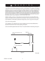
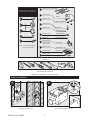
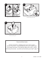
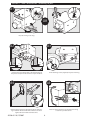
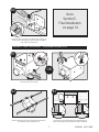
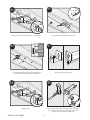
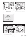
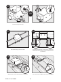
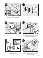
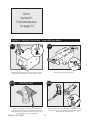
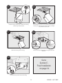
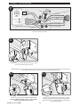
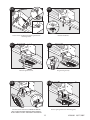
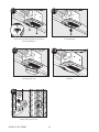
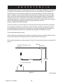
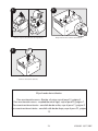
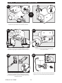
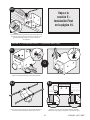
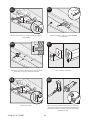
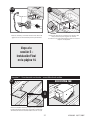
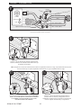
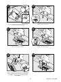
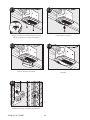
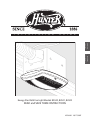
I
n
s
t
a
l
l
a
t
i
o
n
G
u
i
d
e
ENGLISH
See page 2
READ and SAVE THESE INSTRUCTIONS
1
42936-01 10/17/2007
Español
Vea la página 19
Energy Star Bath Fan Light Models 82040, 82041, 82042
W
arning
TO REDUCE THE RISK OF ELECTRIC SHOCK OR INJURY, OBSERVE THE FOLLOWING:
1) Read all instructions before attempting to install or use this appliance. This appliance is for general
ventilating use only. Do not use this appliance for ventilating hazardous or explosive materials. Follow
the heating equipment manufacturer’s guideline and safety standards, such as those published by
the National Fire Prevention Association (NFPA), and the American Society for Heating, Refrigeration
and Air-Conditioning Engineers (ASHRAE), and the local code authorities. Use this appliance only as
described in this manual. Any other use not recommended by the manufacturer may cause
fire, electric shock, or injury to persons. SAVE THESE INSTRUCTIONS.
2) Before installing, servicing, or cleaning the unit, disconnect the power by turning off the circuit
breakers to the outlet box and associated wall switch location. If you cannot lock the circuit breakers
in the off position, securely attach a prominent warning device, such as a tag, to the service panel.
3) This unit must be grounded.
4) This appliance is not suitable for tub or shower installation, and must not be installed within a
minimum of 3 feet from the tub or shower opening. See Figure A.
5) Do not install this appliance lower than 7 feet (2.13 m) above the floor in the ceiling. See Figure A.
Bath Fan
NOTE: This illustration is not
to scale
3 ft. min.
(0.91 m)
7 ft. min.
(2.13 m)
Tub or Shower area
Figure A
42936-01 10/17/2007
2
Continued
6) Never place a switch where it can be reached from a tub or shower. Do not install this appliance in
a tub or shower enclosure.
7) Installation work and electrical wiring must be done by qualified person(s) in accordance with all
applicable codes and standards, including fire-rated construction codes and standards.
8) When cutting or drilling into wall(s) or ceiling, do not damage electrical wiring or other hidden
utilities.
9) Do not install this product in a wall. This product is designed for installation in ceilings up
to a 12/12 pitch (45 degrees). Ductwork must point upward.
10) Ducted fans must always be vented to the outdoors. Keep ducting as short and as straight as possible.
11) Extreme caution is necessary when this appliance is used by or near children or invalids
and whenever the is left operating and unattended.
12) To avoid motor bearing damage and noisy/unbalanced blower wheel, keep drywall spray,
construction dust, etc. off power unit.
13) Read specification label on product for further information and requirements.
14) Do not insert or allow foreign objects to enter any ventilation or exhaust opening as this
may cause an electric shock or fire, or damage the unit.
15) Do not use this appliance with a dimmer switch or a fan speed controller.
16) To reduce the risk of fire or electrical shock, do not use this fan with any solid-state speed control
device.
17) To prevent a possible fire, do not block air intakes or exhaust in any manner.
3
42936-01 10/17/2007
F
95044-01-000 Mounting Rails
Check all the parts. If damaged, call
1-888-830-1326 for replacement.
G
97518-01-000
Housing
x6
A
x2 H
75184-01-133
Light Fixture Thumbnuts
I
* B
3/8” Cable Connector
J
97134-01-000
03242-07-133
Wiring Cover Screw
*C
K
x2 D
Attachment Screws
x4 E
Mounting Screws
* NOTE:
Wiring Cover
L
M
Strain relief (not supplied) cable
connector must be installed.
x2 N
O
P
65872-01-000
74508-53
Strain Relief Bracket
Strain Relief Bracket Screw
97118-02-000
97118-03-000
97118-04-000
74508-03-133
97932-01-262
Fan Assembly
Fan Mounting Screws
Light Fixture
87259-01-000
Lens
Included.
Tools Needed. (Not supplied.)
Estimated assembly time: 30 to 60 minutes
Before Installation
B
A
Loosen the fan mounting screws.
Turn off the power source.
42936-01 10/17/2007
4
D
C
Remove the fan assembly from the housing.
Loosen the wiring cover screw.
E
Remove the wiring cover.
Choose Installation Option
For New Construction - attaching to joist, go to step A1, page 5.
For New Construction - suspended between, joists go to step B1, page 7.
For Existing Construction - accessible from above, go to step C1, page 9.
For Existing Construction - accessible only from below, go to step D1, page 12.
5
42936-01 10/17/2007
Section A - New Construction - attaching to joist
A1
OR
Pop out a wiring access slug.
A3
A2
5/8
1/2
5/8
1/2
Position the correct depth mark at the bottom edge of
the joist based upon the the thickness of your sheetrock.
A4
Drive mounting screws (supplied) into joist or framing.
A5
3”
Run the power supply wire through the strain relief, leaving 3” between the end of the wire and the strain relief.
Tighten the strain relief around the wire.
42936-01 10/17/2007
Install the wiring and the strain relief into the wiring
access hole you made earlier.
6
A6
Go to
Section E Final Installation
on page 14.
Connect 4” duct and vent to the outside. Use duct tape to
secure joints. If ducting does not fit securely, an adapter
may need to be purchased.
Section B - New Construction – suspended between joists
B1
OR
Pop out a wiring access slug.
B2
B3
5/8
1/2
5/8
1/2
Position the correct depth mark at the bottom edge of
the joist based upon the the thickness of your sheetrock.
Slide the mounting rails into brackets. Note the orientation of of the outer ends of the rails.
7
42936-01 10/17/2007
B5
B4
1/16” bit
Drill a pilot hole at the TOP of each outline.
Mark position of screws by using holes as a template.
B7
B6
Insert mounting screws, leaving space between the
screw head and the joist. (Screws are supplied.)
Attach the rails onto the screws.
B8
B9
Tighten screws.
42936-01 10/17/2007
3”
Run the power supply wire through the strain relief, leaving 3” between the end of the wire and the strain relief.
Tighten the strain relief around the wire.
8
B10
B11
Connect 4” duct and vent to the outside. Use duct tape to
secure joints. If ducting does not fit securely, an adapter
may need to be purchased.
Install the wiring and the strain relief into the wiring
access hole you made earlier.
Go to
Section E Final Installation
on page 14.
Section C - Existing Construction – accessible from above
C1
�⁄�
OR
9
11”
”
NO EXISTING FAN
Remove an existing fan and check to make sure the
opening is large enough to accommodate the new fan
housing. The opening needs to be 11” x 9 5/8”.
9
42936-01 10/17/2007
C3
OR
Pop out a wiring access slug.
C3
C4
5/8
1/2
5/8
1/2
Slide the mounting rails into brackets.
Using the depth markings on the housing, position the
bottom edge of the housing so that it will be flush with
the sheetrock.
C6
C5
1/16” bit
Mark position of screws by using holes as a template.
42936-01 10/17/2007
Drill a pilot hole at the TOP of each outline, AS SHOWN.
10
C7
C8
Insert mounting screws, leaving space between the
screw head and the joist. (Screws are supplied.)
Attach the rails onto the screws.
C9
C10
3”
Run the power supply wire through the strain relief, leaving 3” between the end of the wire and the strain relief.
Tighten the strain relief around the wire.
Tighten screws.
C11
C12
Install the wiring and the strain relief into the wiring
access hole you made earlier.
Connect 4” duct and vent to the outside. Use duct tape to
secure joints. If ducting does not fit securely, an adapter
may need to be purchased.
11
42936-01 10/17/2007
Go to
Section E Final Installation
on page 14.
Section D - Existing Construction – accessible from below
D2
D1
Remove one of the wiring access slugs on the top of the
housing. Use a second wiring access plug if needed.
D3
Remove the mounting rail brackets.
D4
EXISTING FAN
Run the power supply wire through the strain relief, leaving
3” between the end of the wire and the strain relief. Tighten
the strain relief around the wire.
Remove an existing fan and check to make sure the
opening is large enough to accommodate the new fan
housing. If there is no existing fan choose an appropriate
location to make an 11” x 9 5/8” opening.
42936-01 10/17/2007
3”
12
D5
D6
Install the wiring and the strain relief into the wiring
access hole you made earlier.
Connect 4” duct and vent to the outside. Use duct tape to
secure joints. If ducting does not fit securely, an adapter
may need to be purchased.
D7
D8
5/8
1/2
5/8
1/2
Position the bottom edge of the housing flush with the
sheetrock.
Move the housing into the ceiling.
D9
Go to
Section E Final Installation
on page 14.
Screw mounting screws into joist or framing.
13
42936-01 10/17/2007
Section E - Final Installation
E1
Ground
Black
Green
White
A
2 Pin
Fan Motor
Light
3 Pin
Black Main Switch 1 (AC In)
White
White
Night Light
Bare Copper
Red Night Light
Black Light
Red Switch 1 (AC In)
*Option
Black Switch 2 (AC In)
*Option Fan & Main Light Together
Connect the wiring as shown.
E2
?
Install the wiring cover box. Make sure all wiring connections are inside the wiring cover box.
NOTE: Though this final installation section shows the housing mounted to a joist, the final installation procedure is the
same whether the housing is mounted to a joist or suspended between joists.
E3
E4
Connect fan wiring harness. DO NOT ALLOW THE FAN
TO HANG FROM THE WIRING HARNESS. INSTALLATION IS
EASIER IF TWO PEOPLE ARE INVOLVED.
Install the fan assembly by inserting the tabs as shown
and pushing the fan assembly into the housing. Make
certain the wiring is not pinched between the fan assembly and the housing.
42936-01 10/17/2007
14
E5
E6
Secure the fan assembly by tightening the two fan
mounting screws.
Remove thumbnuts.
E8
E7
Remove light bulb cover.
Plug in wiring harness.
E10
E9
Position lighting fixture over mounting posts.
Install the strain relief bracket. DO NOT ALLOW THE
LIGHT FIXTURE TO HANG FROM THE WIRING HARNESS.
INSTALLATION IS EASIER IF TWO PEOPLE ARE INVOLVED.
15
42936-01 10/17/2007
E11
E12
Secure the fan assembly by tightening the two fan
mounting thumbnuts.
Install night light.
E13
E14
Install light bulb cover.
Complete.
E9
Restore power at the source.
42936-01 10/17/2007
16
Preventative Maintenance
A clean fan provides better service. Disconnect the power supply and clean the fan as listed below.
TO CLEAN THE BEZEL: Carefully pull the bezel down. Use water, a mild detergent such as dishwashing liquid, and
a soft cloth to clean the bezel. DO NOT use abrasive cloths, steel wool pads, or scouring powders. Dry the bezel
and reinstall it.
TO CLEAN THE FAN ASSEMBLY: Disconnect power to the unit by switching off the breaker or removing the fuse.
Turn the wall switch off. Remove the bezel (as described above). Remove the two fan mounting screws. Remove
the fan from the housing and unplug the fan wiring harness.
Gently vacuum the fan, motor, and the housing interior.
When the fan is clean, plug in the fan wiring harness. Reinstall the fan and tighten the two fan mounting screws.
Reinstall the bezel.
Restore power to the appliance. Test the appliance. If the fan does not run, 1) check the power source, or 2) disconnect power to the appliance, disassemble as described above, check the fan assembly plug, restore power,
and test the unit. If the fan still does not run, contact a qualified installer.
NEVER IMMERSE METAL OR ELECTRICAL COMPONENTS IN WATER.
Maintenance
The fan motor is permanently lubricated and never needs oiling. If the motor bearings are making excessive or
unusual noises, contact Hunter Technical Support (see Troubleshooting section) to order a new fan assembly.
Trouble Shooting
Problem: Fan does not come on.
Solution:
• Turn power on, replace fuse, or reset breaker.
• Hunter Fan Bath Ventilators are extremely quiet. To confirm that the fan is running, place your hand near
the vents to feel the air movement.
• Check all plug connections to be sure they are secure.
• Check the wiring to make sure it matches the wiring diagram.
Problem: Light does not come on.
Solution:
• Replace the light bulb with a new bulb.
• Turn power on, replace fuse, or reset breaker.
• Check all plug connections to be sure they are secure.
• Check the wiring to make sure it matches the wiring diagram.
Problem: Fan is noisy.
Solution:
• Check and tighten all fasteners.
• Check the bezel to make sure it is secure.
• Check the flapper to make sure it moves freely.
17
42936-01 10/17/2007
Trouble Shooting (cont.)
If you need parts or service assistance, please call 888-830-1326 or visit us at our website at http://www.
hunterfan.com.
Warranty
Hunter Fan Company
Bath Fan
LIMITED WARRANTY
Hunter Fan Company makes the following limited warranty to the original user or consumer purchaser of this Hunter Bath
Fan:
If any part of your Hunter Bath Fan fails at any time within one year after the date of sale to you due to a defect in material
or workmanship, we will repair or, at our option, replace the defective part free of charge for parts and labor performed at
our Service Department in Memphis, Tennessee. After this one-year period, you will be responsible for all parts and labor
costs for repairs on the Bath Fan except for motor repairs as provided below.
If your Hunter Bath Fan motor fails at any time within five years after the date of sale to you due to a defect in material or
workmanship, labor and materials to repair the defect will be provided free of charge at our Service Department in Memphis, Tennessee. If no replacement part can be provided, we will, at our option, either refund the actual purchase price of
your Bath Fan or provide a replacement free of charge. After this five-year period, you will be responsible for all parts and
labor costs for repairs on all parts of the bath exhaust fan.
IF THE ORIGINAL USER OR CONSUMER PURCHASER CEASES TO OWN THE FAN, THIS WARRANTY AND ANY IMPLIED WARRANTY WHICH THEN REMAINS IN EFFECT, INCLUDING BUT NOT LIMITED TO ANY IMPLIED WARRANTY OF MERCHANTABILITY
OR FITNESS FOR A PARTICULAR PURPOSE, ARE VOIDED. NO WARRANTY, EXPRESS OR IMPLIED, INCLUDING ANY WARRANTY
OF MERCHANTABILITY OR FITNESS FOR A PARTICULAR PURPOSE, IS MADE IN RESPECT OF GLASS FIXTURES OR LIGHT BULBS
OR THE FINISH ON ANY METAL PORTION OF THE BATH EXHAUST FAN.
THIS WARRANTY IS IN LIEU OF ALL OTHER EXPRESS WARRANTIES. THE DURATION OF ANY IMPLIED WARRANTY, INCLUDING,
BUT NOT LIMITED TO, ANY IMPLIED WARRANTY OF MERCHANTABILITY OR FITNESS FOR A PARTICULAR PURPOSE, IN RESPECT TO ANY HUNTER FAN BATH FAN MOTOR OR OTHER FAN PART, IS EXPRESSLY LIMITED TO THE PERIOD OF THE EXPRESS
WARRANTY SET FORTH ABOVE FOR SUCH MOTORS OR OTHER PARTS.
This warranty is voided if your Hunter Bath Fan is not purchased and installed in the U.S.A. This warranty excludes and does
not cover defects, malfunctions or failures of any Hunter Bath Fan which were caused by repairs by persons not authorized
by us, use of parts or accessories not authorized by us, mishandling, improper installation, modifications or damage to
the Hunter Bath Fan while in your possession, or unreasonable use, including failure to provide reasonable and necessary
maintenance.
To obtain servicing, contact Hunter Fan Company Technical Support at 1-888-830-1326. Please contact us before shipping
your Bath Fan to us. If we authorize you to ship it to us, you will be responsible for all insurance and freight or other transportation charges to our factory or Service Department. We will return your Hunter Bath Fan freight prepaid. Your Hunter
Bath Fan should be properly packed to avoid damage in transit since we will not be responsible for any such damage. Proof
of purchase is required when requesting warranty service. The purchaser must present the sales receipt or other document
that establishes proof of purchase.
IN NO EVENT SHALL HUNTER FAN COMPANY BE LIABLE FOR CONSEQUENTIAL OR INCIDENTAL DAMAGES.
SOME STATES DO NOT ALLOW LIMITATIONS ON HOW LONG AN IMPLIED WARRANTY LASTS OR THE EXCLUSION OR LIMITATION OF INCIDENTAL OR CONSEQUENTIAL DAMAGES SO THE ABOVE LIMITATION OR EXCLUSIONS MAY NOT APPLY TO YOU.
THE WARRANTY GIVES YOU SPECIFIC LEGAL RIGHTS AND YOU MAY ALSO HAVE OTHER RIGHTS WHICH VARY FROM STATE TO
STATE.
Hunter Fan Company
2500 Frisco Avenue
Memphis, Tennessee 38114
42936-01 10/17/2007
18
Printed in China
G
U
Í
A
D
E
I
N
S
T
A
L
A
C
I
Ó
N
Español
Ventilador para baño con lámpara Energy Star Modelos 82040, 82041 y 82042
LEA y GUARDE ESTAS INSTRUCCIONES
19
42936-02 10/17/2007
A D V E R T E N C I A
PARA REDUCIR EL RIESGO DE DESCARGA ELÉCTRICA O LESIONES, OBSERVE LO SIGUIENTE:
1) Lea todas las instrucciones antes de intentar instalar o usar este artefacto. Este artefacto está
diseñado sólo para uso de ventilación general. No use este artefacto para ventilar materiales peligrosos o explosivos. Siga las pautas del fabricante del equipo de calefacción y las normas de seguridad, como las de la Asociación Nacional de Protección contra Incendios (NFPA), la Asociación de
Ingenieros Americanos en Calefacción y Aire acondicionado (ASHRAE), y los códigos locales. Use
este artefacto sólo como se describe en el manual de instrucciones. Cualquier otro uso no recomendado por el fabricante, puede causar incendio, choque eléctrico o lesiones a
personas. GUARDE ESTAS INSTRUCCIONES.
2) Antes de instalar, dar servicio o limpiar la unidad, desconecte la alimentación eléctrica apagando
los interruptores automáticos que alimentan a la caja de salida y al respectivo interruptor de pared.
Si no puede bloquear los interruptores automáticos en la posición de apagado, fije firmemente una
forma destacada de advertencia, como una etiqueta
A6 de seguridad, en el tablero de servicio.
3) Esta unidad debe ponerse a tierra.
4) Este artefacto no es adecuado para instalarlo en una bañera o ducha, y no debe instalarse a menos
de 3 pies de la tubería de suministro de agua de la bañera o ducha. Vea la Figura A.
5) No instale este artefacto a una altura menor de 7 pies (2.13 m) por encima del piso, en el techo. Vea la
Figura A.
Bath Fan
NOTE: This illustration is not
to scale
3 ft. min.
(0.91 m)
7 ft. min.
(2.13 m)
Tub or Shower area
Figura A
42936-02 10/17/2007
20
Continuación
6) Nunca coloque un interruptor donde pueda ser alcanzado desde una tina o una ducha. No instale
este artefacto en el perímetro de la bañera o ducha.
7) Los trabajos de instalación y cableado eléctrico deben ser realizados por personas calificadas de
acuerdo con todos los códigos y las normas aplicables, incluyendo los códigos y normas de construcción contra incendio.
8) Al cortar o taladrar en paredes o techo, no dañe el cableado eléctrico u otros servicios no visibles.
9) No instale este producto en una pared. Este producto está diseñado para instalarse en
techos con una inclinación de hasta 12/12 (45º). La red de ductos debe dirigirse hacia arriba.
10) Los ventiladores canalizados siempre deben descargar al aire libre. Mantenga los ductos tan cortos y rectos como sea posible.
11) Es necesario tener mucho cuidado cuando se usa alguno de estos donde haya niños o
personas discapacitadas y siempre que estén en funcionamiento y sin supervisión.
12) Para evitar daños al rodamiento del motor y ventiladores ruidosos o desbalanceados,
mantenga la unidad de potencia lejos de la aplicación de aerosol para paneles de yeso
(drywall), polvo de la construcción, etc.
13) Vea más información y los requisitos en la etiqueta de especificación del producto.
14) No introduzca ni permita el ingreso de objetos extraños en ninguna abertura de ventilación o escape ya que puede causar choque eléctrico o incendio, o dañar la unidad.
15) No use este artefacto con un atenuador o control de velocidad del ventilador.
16) Para reducir el riesgo de incendio o choque eléctrico, no use este ventilador con ningún dispositivo de estado sólido para control de velocidad.
17) Para evitar un posible incendio, no bloquee de ninguna manera las entradas o aberturas
de escape.
21
42936-02 10/17/2007
Revise todas las piezas. Si están
dañadas, llame al 1-888-830-1326
para un reemplazo.
F
G
95044-01-000 Rieles de montaje
97518-01-000
Alojamiento
x6
A
x2 H
*
B
I
Conector de cable de 3/8”
J
75184-01-133
97134-01-000
03242-07-133
*C
K
x2 D
Tornillos accesorios
x4 E
Tornillos de montaje
* NOTA:
L
M
Debe instalar un aliviador de tensiones
(no suministrado) para el conector de
x2 N
O
P
Tuercas de mariposa
de la lámpara
65872-01-000
Cubierta del cableado
Tornillo de la cubierta
del cableado
Soporte del aliviador de
tensiones
74508-53
Tornillo de soporte del aliviador de
tensiones
97118-02-000
Conjunto del ventilador
97118-03-000
97118-04-000
74508-03-133
97932-01-262
Tornillos de montaje del ventilador
Lámpara
87259-01-000
Indicador
Incluido.
Se necesitan herramientas. (No suministradas)
Tiempo estimado de ensamblaje: entre 30 y 60 minutos
Antes de la instalación
B
A
Afloje los tornillos de montaje del ventilador.
Apague la fuente de alimentación.
42936-02 10/17/2007
22
D
C
Retire el conjunto del ventilador del alojamiento.
Afloje el tornillo de la cubierta del cableado.
E
Retire la cubierta del cableado.
Elija el modo de instalación
Para construcción nueva - fijación a la viga, vaya al paso A1, página 5.
Para construcción nueva - suspendido entre vigas, vaya al paso B1, página 7.
Para construcción existente - accesible desde arriba, vaya al paso C1, página 9.
Para construcción existente - accesible sólo desde abajo, vaya al paso D1, página
12.
23
42936-02 10/17/2007
Sección A - Construcción nueva - fijación a la viga.
A1
O
Expulse un tapón metálico de acceso del cableado.
A3
A2
5/8
1/2
5/8
1/2
Ubique la correcta marca de profundidad en el borde
inferior de la viga, según el espesor de su plancha de yeso.
A4
Instale los tornillos de montaje (suministrados)
en la viga o el marco.
A5
3”
Deslice el cable de alimentación eléctrica por el aliviador
de tensiones, dejando 3” entre el extremo del alambre
y el aliviador de tensiones. Apriete el aliviador de tensiones
alrededor del cable.
42936-02 10/17/2007
Instale el cableado y el aliviador de tensiones dentro del
agujero de acceso del cableado que hizo previamente.
24
A6
Vaya a la
sección E –
Instalación Final
en la página 14.
Conecte un ducto de 4” y ventile hacia el exterior. |Use cinta
para ductos para asegurar las uniones. Si el ducto no se
ajusta firmemente, puede ser necesario comprar
un adaptador.
Sección B - Construcción nueva – suspendido entre vigas
B1
O
Expulse un tapón metálico de acceso del cableado.
B2
B3
5/8
1/2
5/8
1/2
Ubique la correcta marca de profundidad en el borde
inferior de la viga, según el espesor de su plancha de yeso.
Deslice los rieles de montaje en los soportes. Observe la
orientación de los extremos externos de los rieles.
25
42936-02 10/17/2007
B5
B4
1/16” bit
Taladre un agujero modelo en la parte SUPERIOR
de cada perfil.
Marque la ubicación de los tornillos usando los agujeros
como plantilla.
B7
B6
Introduzca los tornillos, dejando espacio entre la cabeza
del tornillo y la viga. (Se suministran tornillos).
Fije los rieles en los tornillos.
B9
B8
Apriete los tornillos.
42936-02 10/17/2007
3”
Deslice el cable de alimentación eléctrica por el aliviador
de tensiones, dejando 3” entre el extremo del alambre y
el aliviador de tensiones. Apriete el aliviador de tensiones
alrededor del cable.
26
B10
B11
Conecte un ducto de 4” y ventile hacia el exterior. Use
cinta para ductos para asegurar las uniones.
Si el ducto no se ajusta firmemente, puede ser necesario
comprar un adaptador.
Instale el cableado y el aliviador de tensiones dentro del
agujero de acceso del cableado que hizo previamente.
Vaya a la
sección E –
Instalación Final
en la página 14.
Sección C - Construcción existente – accesible desde arriba
C1
�⁄�
9
11”
”
NO EXISTING FAN
O
Retire el ventilador existente y asegúrese que la abertura
sea suficientemente grande para acomodar el alojamiento
del ventilador nuevo. La abertura debe ser de 11” x 9 5/8”.
27
42936-02 10/17/2007
C3
O
Expulse un tapón metálico de acceso del cableado.
C3
C4
5/8
1/2
5/8
1/2
Deslice los rieles de montaje en los soportes.
Usando las marcas de profundidad en el alojamiento,
ubique el borde inferior del alojamiento de modo que el
alojamiento esté a nivel con la plancha de yeso.
C6
C5
1/16” bit
Marque la ubicación de los tornillos usando los agujeros
como plantilla.
42936-02 10/17/2007
Taladre un agujero modelo en la parte SUPERIOR
de cada perfil COMO SE MUESTRA.
28
C7
C8
Introduzca los tornillos, dejando espacio entre la cabeza del
tornillo y la viga. (Se suministran tornillos)
Fije los rieles en los tornillos.
C9
C10
3”
Deslice el cable de alimentación eléctrica por el aliviador
de tensiones, dejando 3” entre el extremo del alambre y
el aliviador de tensiones. Apriete el aliviador de tensiones
alrededor del cable.
Apriete los tornillos.
C11
C12
Instale el cableado y el aliviador de tensiones dentro del
agujero de acceso del cableado que hizo previamente.
Conecte un ducto de 4” y ventile hacia el exterior. Use cinta
para ductos para asegurar las uniones. Si el ducto no se ajusta firmemente, puede ser necesario comprar un adaptador.
29
42936-02 10/17/2007
Vaya a la
sección E –
Instalación Final
en la página 14.
Sección D - Construcción existente – accesible desde abajo
D2
D1
Retire uno de los tapones metálicos de acceso del cableado
en la parte superior del alojamiento. De ser necesario, use
un segundo tapón metálico de acceso del cableado.
D3
Retire los soportes de los rieles de montaje.
D4
EXISTING FAN
Deslice el cable de alimentación eléctrica por el aliviador de
tensiones, dejando 3” entre el extremo del alambre y el aliviador de tensiones. Apriete el aliviador de tensiones alrededor
del cable.
Retire el ventilador existente y asegúrese que la abertura
sea suficientemente grande para acomodar el alojamiento del ventilador nuevo. Si no hay un ventilador existente,
elija una ubicación apropiada para hacer una abertura de
11” x 9 5/8”.
42936-02 10/17/2007
3”
30
D5
D6
Instale el cableado y el aliviador de tensiones dentro del
agujero de acceso del cableado que hizo previamente.
Conecte un ducto de 4” y ventile hacia el exterior. Use cinta
para ductos para asegurar las uniones. Si el ducto
no se ajusta firmemente, puede ser necesario comprar
un adaptador.
D7
D8
5/8
1/2
5/8
1/2
Ubique el borde inferior del alojamiento a nivel con la
plancha de yeso.
Mueva el alojamiento en la placa de techo.
D9
Vaya a la
sección E –
Instalación Final
en la página 14.
Atornille los tornillos de montaje en la viga o el marco.
31
42936-02 10/17/2007
Sección E - Instalación Final
E1
Ground
Black
Green
White
A
2 Pin
Fan Motor
Light
3 Pin
Black Main Switch 1 (AC In)
White
White
Night Light
Bare Copper
Red Night Light
Black Light
Red Switch 1 (AC In)
*Option
Black Switch 2 (AC In)
*Option Fan & Main Light Together
Conecte los alambres como se muestra.
E2
?
Instale la caja de cubierta del cableado. Asegúrese que
todas las conexiones de cableado estén dentro de la caja
de cubierta del cableado.
NOTA: Aunque esta sección de instalación final muestra el alojamiento montado a la viga, el procedimiento de instalación
final es el mismo ya sea que el alojamiento esté montado a la viga o suspendido entre las vigas.
E3
E4
Conecte el manojo de alambres del ventilador. NO PERMITA
QUE EL VENTILADOR QUEDE SUSPENDIDO DEL MANOJO
DE ALAMBRES. ESTE VENTILADOR SE INSTALA MÁS
FÁCILMENTE ENTRE DOS PERSONAS.
Instale el conjunto del ventilador introduciendo las
pestañas como se muestra y empujándolo hacia el
alojamiento. Asegúrese que el cableado no esté atrapado
entre el conjunto del ventilador y el alojamiento.
42936-02 10/17/2007
32
E5
E6
Asegure el conjunto del ventilador apretando los dos
tornillos de montaje del ventilador.
Retire las tuercas de mariposa.
E8
E7
Retire la cubierta de la bombilla.
Conecte el manojo de alambres.
E10
E9
Instale el soporte del aliviador de tensiones. NO PERMITA
QUE LA LÁMPARA QUEDE SUSPENDIDA DEL MANOJO
DE ALAMBRES. SE INSTALA MÁS FÁCILMENTE ENTRE
DOS PERSONAS.
Ubique la lámpara sobre los postes de montaje.
33
42936-02 10/17/2007
E11
E12
Asegure el conjunto del ventilador apretando las dos
tuercas de mariposa de montaje del ventilador.
Instale la lámpara de noche.
E13
E14
Instale la cubierta de la bombilla.
Complete.
E9
Restablezca la energía en la fuente de alimentación.
42936-02 10/17/2007
34
MANTENIMIENTO PREVENTIVO
Un ventilador limpio proporciona mejor servicio. Desconecte la alimentación eléctrica y limpie el ventilador
como se indica a continuación.
PARA LIMPIAR EL BISEL: Tire cuidadosamente del bisel hacia abajo. Use agua, un detergente suave como líquido para lavar platos y un paño suave para limpiar la pantalla. NO emplee paños abrasivos, almohadillas de lana
de acero ni polvos para fregar. Seque el bisel y reinstálelo.
PARA LIMPIAR EL CONJUNTO DEL VENTILADOR: Desconecte la unidad apagando el interruptor automático o
retirando el fusible. Apague el interruptor de pared. Retire el bisel (como se describe arriba). Retire los dos tornillos de montaje del ventilador. Retire el ventilador del alojamiento y desconecte el manojo de alambres del
ventilador.
Suavemente aspire el ventilador, el motor y el interior del alojamiento.
Cuando el ventilador esté limpio, conecte el manojo de alambres del ventilador. Reinstale el ventilador y apriete
los dos tornillos de montaje del ventilador. Reinstale el bisel.
Restablezca la alimentación al artefacto. Pruebe el artefacto. Si el ventilador no funciona, 1) verifique la fuente
de energía, ó 2) desconecte la energía del artefacto, desmonte como se describe anteriormente, revise el enchufe del conjunto del ventilador, restablezca la alimentación y pruebe la unidad. Si su ventilador todavía no funciona, contacte a un instalador calificado.
JAMÁS SUMERJA LOS COMPONENTES METÁLICOS NI ELÉCTRICOS EN AGUA.
Mantenimiento
El motor del ventilador está lubricado permanentemente y no necesita ser engrasado. Si los rodamientos del
motor están haciendo ruidos excesivos o inusuales, contacte al Soporte técnico de Hunter (vea la sección
Solución de problemas) para ordenar un nuevo conjunto de ventilador.
Solución de problemas
Problema: El ventilador no está funcionando.
Solución:
• Encienda la alimentación eléctrica, reemplace el fusible o restablezca el interruptor automático.
• Losventiladores de baño Hunter son muy silenciosos. Para confirmar que el ventilador esté funcionando, coloque su
mano cerca de los conductos de ventilación para sentir el movimiento del aire.
• Verifique todas las conexiones de los enchufes para asegurarse que estén firmes.
• Verifique el cableado para asegurarse que coincida con el diagrama de cableado.
Problema: La luz no funciona.
Solución:
• Reemplace la bombilla con una nueva.
• Encienda la alimentación eléctrica, reemplace el fusible o restablezca el interruptor automático.
• Verifique todas las conexiones de los enchufes para asegurarse que estén firmes.
• Verifique el cableado para asegurarse que coincida con el diagrama de cableado.
Problema: El ventilador hace ruido.
Solución:
• Verifique y apriete todos los pernos y tornillos.
• Revise el bisel para asegurarse que esté firme.
• Verifique la válvula de retención para asegurarse que se mueva con libertad.
Si necesita repuestos o servicio, llame al 888-830-1326 o viste nuestro sitio web en http://www.hunterfan.com.
35
42936-02 10/17/2007
Garantía
Hunter Fan Company
Ventilador para baño
GARANTÍA LIMITADA
Hunter Fan Company establece la siguiente garantía limitada al usuario o comprador original de este ventilador para baño
de Hunter:
Si alguna pieza de su ventilador para baño Hunter falla en cualquier momento dentro de un año después de la fecha
de compra debido a una falla de material o mano de obra, repararemos o, a nuestra elección, reemplazaremos la pieza
defectuosa sin costo para partes y mano de obra realizada en nuestro Departamento de servicio en Memphis, Tennessee.
Después de este período de un año, usted será responsable de todos los costos de partes y mano de obra para reparaciones
en el ventilador para baño, con excepción de reparaciones del motor como se estipula a continuación.
Si el motor de su ventilador para baño Hunter falla en cualquier momento dentro de cinco años después de la fecha
de compra debido a una falla de material o mano de obra, la mano de obra y los materiales para reparar la falla serán
proporcionados sin costo en nuestro Departamento de servicio en Memphis, Tennessee. Si no puede proporcionarse
alguna parte de reemplazo, a nuestra elección, le reembolsaremos el precio de compra verdadero de su ventilador para
baño o le proporcionamos uno de reemplazo sin costo. Después de este período de cinco años, usted será responsable de
todos los costos de partes y mano de obra para reparaciones de cualquier componente del Extractor de aire para baño.
SI EL USUARIO O COMPRADOR ORIGINAL DEJA DE POSEER EL EXTRACTOR DE AIRE, ESTA GARANTÍA Y CUALQUIER
GARANTÍA IMPLÍCITA QUE PERMANEZCA EN EFECTO, INCLUYENDO PERO SIN LIMITARSE A TODA GARANTÍA IMPLÍCITA
DE COMERCIABILIDAD O IDONEIDAD PARA UN PROPÓSITO PARTICULAR, QUEDA ANULADA. NO SE OFRECE NINGUNA
GARANTÍA EXPRESA O IMPLÍCITA, INCLUYENDO CUALQUIER GARANTÍA DE COMERCIABILIDAD O IDONEIDAD PARA UN
PROPÓSITO PARTICULAR, EN RELACIÓN CON LAS LÁMPARAS DE VIDRIO O LAS BOMBILLAS O EL ACABADO EN CUALQUIER
PARTE METÁLICA DEL EXTRACTOR DE AIRE PARA BAÑO.
ESTA GARANTÍA SUSTITUYE A TODAS LAS OTRAS GARANTÍAS EXPRESAS. LA DURACIÓN DE TODA GARANTÍA IMPLÍCITA,
INCLUYENDO PERO SIN LIMITARSE A CUALQUIER GARANTÍA IMPLÍCITA DE COMERCIABILIDAD O IDONEIDAD PARA UN
PROPÓSITO PARTICULAR, CON RESPECTO DE CUALQUIER MOTOR DE VENTILADOR PARA BAÑO HUNTER U OTRA PARTE DEL
VENTILADOR, ESTÁ EXPRESAMENTE LIMITADA AL PERIODO DE LA GARANTÍA EXPRESA ESTABLECIDA ANTERIORMENTE PARA
DICHOS MOTORES U OTRAS PARTES.
Esta garantía es nula si su ventilador para baño no se adquiere e instala en los EE.UU. Esta garantía excluye y no cubre defectos,
averías o fallas de cualquier ventilador para baño Hunter que fueran ocasionados por reparaciones por parte de personas no
autorizadas por nosotros, por el uso de piezas o accesorios no autorizados por nosotros, por mal uso, instalación incorrecta,
modificaciones, o daños al ventilador para baño Hunter mientras esté en su posesión, o por un empleo no razonable,
incluyendo la falla al proporcionar mantenimiento necesario y razonable.
Para obtener soporte técnico, llame a Hunter Fan Company al 1-888-830-1326. Le agradeceremos que se ponga en
contacto con nosotros antes de enviarnos su ventilador y calentador para baño. Si le autorizamos a enviarlo, usted será
responsable de todos los cargos de seguro y flete o de otros cargos de transporte a nuestra planta o Departamento de
Servicio. Devolveremos su ventilador para baño Hunter con el flete prepagado. Su ventilador para baño Hunter se debe
embalar apropiadamente para evitar daños durante el tránsito ya que no seremos responsables de dichos daños. Debe
proporcionar una prueba de su compra cuando solicite un servicio de garantía. El comprador debe presentar el recibo de
compra u otro documento que establezca la prueba de su compra.
EN NINGÚN CASO HUNTER FAN COMPANY SERÁ RESPONSABLE DE DAÑOS PERJUDICIALES O ACCESORIOS.
ALGUNOS ESTADOS NO PERMITEN LIMITACIONES SOBRE LA DURACIÓN DE UNA GARANTÍA IMPLÍCITA O LA EXCLUSIÓN O LIMITACIÓN DE DAÑOS ACCESORIOS O PERJUDICIALES, ASÍ QUE LA LIMITACIÓN O EXCLUSIONES ANTES MENCIONADAS PUEDEN
NO APLICARSE A USTED.
LA GARANTÍA LE DA DERECHOS LEGALES ESPECÍFICOS, PERO USTED TAMBIÉN PUEDE TENER OTROS DERECHOS QUE
VARÍAN DE ESTADO A ESTADO.
Hunter Fan Company
2500 Frisco Avenue
Memphis, Tennessee 38114
42936-02 10/17/2007
36
Impreso en China