1
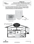
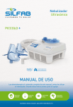
Français Canadien : Capteures à distance – Modèle 43658
Model 43658
SPÉCIFICATIONS
■
■
■
■
■
Capteurs (à distance) de température
Connexion de 2 fils, aucune source d’alimentation séparée nécessaire
Plage de mesure : 15˚F to 99˚F (-9˚C to 37˚C)
Précision : +/- 1˚F (+/- 0.5˚C)
Distance maximale de branchement: 100 m (328 ft) avec du fil blindé de calibre 20 à
deux conducteurs
■ Il FAUT conserver la polarité entre le capteur et le thermostat
3. Tirer les fils identifiés par l’ouverture à l’arrière du boîtier du capteur. (Figure 2)
Fixer le capteur au mur avec les deux vis fournies et mettre de niveau pour l’apparence
à l’aide des coins du bas.
4. Dénuder l’extrémité de chaque fil sur environ 6,4 mm (1⁄4 po) et façonner un petit crochet Le placer derrière la vis et la rondelle à chaque borne qui correspond au fil identifié
et serrer fortement. (Figure 3) Enclencher le couvercle frontal sur le boîtier arrière.
REMARQUE :Si le fil utilisé est blindé, connecter le blindage aux bornes NÉGATIVES
du capteur à distance et du thermostat. (RS-, RS1- ou RS2-)
POUR USAGE INTÉRIEUR SEULEMENT
RS+
RS–
Pour usage avec ces modèles de thermostat de Climate Technology SEULEMENT : 43058, 43558
INSTALLATION
RS+
REMARQUE : Fermer l’alimentation du système avant de commencer l’installation.
Tous les câblages doivent être conformes aux codes électriques nationaux et locaux.
Voir les directives du thermostat de Climate Technology pour les détails du câblage du thermostat. Suivre les directives de l’étape 4 ci-dessous pour connecter les fils du capteur aux
bornes du thermostat.
1. Emplacement : Fixer le capteur à 1,5 m (5 pi) du plancher contre un mur intérieur seulement. Ne pas placer le capteur dans des endroits susceptibles d’être affectés par des
courants d’air provenant de portes ou de gaines ou par la lumière solaire directe ou
autres sources de chaleur.
2. À l’aide des languettes situées à l’arrière du couvercle frontal, dégager la plaque du
boîtier de l’unité. (Figure 1) Identifier les 2 fils du capteur sortant du thermostat avec les
étiquettes incluses, en vous assurant de bien faire correspondre la polarité des fils du
capteur au thermostat.
REMOTE
SENSOR
Figure 1
Onglet
RS–
Blindage
Figure 3
Figure 2
FONCTIONNEMENT
Voir les directives du thermostat de Climate Technology pour plus de détails.
1. Remettre l’alimentation du système en marche et assurez-vous que le thermostat
est alimenté.
2. Dans la minute, le thermostat affichera “Found RM1” et/ou “Found RM2”. Cela
signifie que le thermostat communique correctement avec le capteur. Si le thermostat a
un problème pour communiquer avec le capteur après l’avoir repéré, “Check RM1”
ou “Check RM2” s’affichera.
3. Appuyer sur la touche OPTION sur le thermostat pour sélectionner l’ajustage préalable pour les capteurs local et à distance et pour voir la température mesurée par
chaque capteur.
4. S’il y a un problème avec les capteurs à distance installés, c’est la lecture de température du capteur local qui sera utilisée.
DÉPANNAGE
A Hunter Fan company
Climate Technology Corp.
2500 FRISCO AVENUE
MEMPHIS, TN 38114
© 2003, Climate Technology Corp Form No. 41667, 12/03
41667_final_revised.pmd
1
Il FAUT respecter la polarité pour que le capteur fonctionne. Les bornes RS+ et RSdu thermostat doivent correspondre aux bornes des capteurs 1 ou 2, soit RS1+ et
RS1- ou RS2+ et RS2-.
REMARQUE : Pour des distances plus courtes (jusqu’à 30 m [100 pi]), du fil standard
ou du fil torsadé pourrait fonctionner pour des systèmes de pompes à chaleur. Pour
de plus longues distances, des systèmes multi-phases ou pour tout emplacement avec
du bruit électrique, utiliser du câble blindé de calibre 20.
Si le capteur ne fonctionne pas, vérifier les points suivants :
1. Vérifier la correspondance de polarité entre le capteur et le thermostat. Vérifier également
que les fils du capteur vont aux bornes du capteur 1 (RS1) ou 2 (RS2) correspondant.
2. Si le fil est standard, changer pour du câble blindé de calibre 20. S’assurer que le blindage
est connecté aux bornes négatives.
3. Vérifier que les fils sont bien serrés aux bornes du capteur et du thermostat.
Si vous avez d’autres problèmes, appeler au 1-800-676-7861 entre 8 h et 17 h, heure des
Prairies pour une assistance technique.
12/11/03, 4:23 PM
English: Remote Sensor – Model 43658
Español: Sensor remoto – Modelo 43658
SPECIFICATIONS
■
■
■
■
■
Remote temperature sensor
2 wire connection, no separate power supply needed
Measurement range: 15˚F to 99˚F (-9˚C to 37˚C)
Accuracy: +/- 1˚F (+/- 0.5˚C)
Maximum connection distance: 328 ft. (100 m) with 20 gauge 2-conductor
shielded wire
■ Polarity MUST be maintained between sensor and thermostat
3. Pull the labeled wires through the opening on the sensor back housing. (Figure 2)
Secure the sensor to the wall with the 2 screws provided, and level for appearance
using the bottom corners.
4. Strip a bare end on each wire approximately 1⁄4” long, and bend to a small hook. Place
behind the screw and washer for each terminal that matches the labeled wire, and tighten
securely. (Figure 3) Snap the front cover onto the back housing.
NOTE: When using shielded wire, connect the shield to the NEGATIVE terminal at
the remote sensor and thermostat. (RS–, RS1– or RS2–)
RS+
INDOOR USE ONLY
Figure 1
Tab
Polarity MUST be followed for the sensor to work. The RS+ and RS- terminals
must match the corresponding sensor 1 or 2 terminals on the thermostat, either RS1+ and RS1- or RS2+ and RS2-.
NOTE: For shorter distances (up to 100 ft. / 30m), standard or twisted pair wire
may work on Heat Pump systems. For longer distances, multi-stage systems, or
any site with electrical noise, use 20 gauge shielded wire.
41667_final_revised.pmd
2
Sensor remoto de temperatura
Conexión de 2 alambres, no requiere alimentación eléctrica separada
Rango de medición: 15˚ F a 99˚ F (-9˚ C a 37˚ C)
Exactitud: +/- 1˚ F (+/- 0.5˚ C)
Máxima distancia de conexión: 100 m (328 pies) con cable blindado de 2
conductores calibre 20
■ DEBE mantenerse la polaridad entre el sensor y el termostato
SÓLO PARA USO EN INTERIORES
3. Tire de los alambres etiquetados a través de la abertura en el alojamiento posterior del
sensor. (Figura 2)
Asegure el sensor a la pared con los 2 tornillos suministrados, y nivele para obtener una
mejor apariencia usando las esquinas inferiores.
4. Pele el extremo de cada alambre, aproximadamente 1⁄4" y dóblelo formando un pequeño
gancho. Colóquelo detrás del tornillo y la arandela para cada terminal que coincida con el
alambre etiquetado y apriete firmemente. (Figura 3) Cierre la cubierta delantera en el alojamiento posterior hasta escuchar un clic.
NOTA: Al usar cable blindado, conecte la pantalla de blindaje al terminal NEGATIVO
en el sensor remoto y en el termostato. (RS-, RS1- o RS2-)
RS+
Sólo para uso con los siguientes modelos de termostatos Climate Technology: 43058, 43558
RS–
INSTALACIÓN
RS+
NOTE: Turn off power to the system before starting the installation.
All wiring should conform to national and local electrical codes.
Refer to the Climate Technology thermostat instructions for details on wiring the thermostat. Follow the instructions in Step 4 below when connecting the sensor wires to the
terminals on the thermostat.
1. Location: Mount sensor 5 feet from the floor on an inside wall only. Do not locate the
sensor where it is affected by strong drafts from door or ducts, or from direct sunlight
or other heat generating sources.
2. Using the tabs on the back of the front cover, pop the cover plate off the unit. (Figure
1) Label the 2 sensor wires from the thermostat with the included wire labels, being
sure to match the polarity of the sensor wires at the thermostat.
■
■
■
■
■
RS–
For use with these Climate Technology Thermostat Models ONLY: 43058, 43558
INSTALLATION
ESPECIFICACIONES
RS–
Shield
Figure 2
Figure 3
OPERATION
Refer to the instructions included with the Climate Technology thermostat for more details.
1. Turn power back on to the system, and be sure the thermostat is powered.
2. Within a minute, the thermostat will display “Found RM1” and/or “Found RM2”.
This means that the thermostat is communicating properly with the remote sensor.
After locating the sensor, if the thermostat has a problem communicating with the
sensor, “Check RM1” or “Check RM2” will appear.
3. Press the OPTION key on the thermostat to select the weighting for the Local and
remote sensor(s), and to see the measured temperature for each sensor.
4. If there is a problem with the installed remote sensors, then the Local sensor reading
will be used for the temperature.
NOTA: Corte la alimentación al sistema antes de empezar la instalación.
Todo el cableado debe cumplir los códigos eléctricos locales y nacionales.
Consulte las instrucciones del termostato Climate Technology para obtener detalles sobre
el cableado del termostato. Siga las instrucciones en el paso 4 al conectar los alambres
del sensor a los terminales en el termostato.
1. Ubicación: Monte el sensor a 1.5 metros del piso, solamente en una pared interior. No
ubique el sensor donde sea afectado por corrientes fuertes de la puerta o los ductos,
o de la luz solar directa u otras fuentes de calor.
2. Usando las lengüetas de la parte posterior de la cubierta delantera, retire la placa de
cubierta de la unidad. (Figura 1) Etiquete los 2 alambres del sensor del termostato
con las etiquetas incluidas, asegurándose de hacer coincidir la polaridad de los alambres del sensor en el termostato.
Figura 1
Pestaña
RS+
RS–
Pantalla de blindaje
Figura 3
Figura 2
OPERACIÓN
Consulte las instrucciones incluidas con el termostato Climate Technology para más detalles.
1. Encienda nuevamente la alimentación al sistema, y asegúrese que el termostato esté
alimentado.
2. Dentro de un minuto, el termostato visualizará “Found RM1” y/o “Found RM2”.
Esto significa que el termostato se está comunicando correctamente con el sensor remoto. Después de ubicar el sensor, si el termostato tiene un problema de comunicación con
el sensor, aparecerán “Check RM1” o “Check RM2”.
3. Presione la tecla OPTION en el termostato para seleccionar la ponderación para los
sensores local y remoto, y para ver la temperatura medida para cada sensor.
4. Si hubiera un problema con los sensores remotos instalados, se usará la lectura del
sensor local para la temperatura.
TROUBLESHOOTING
LOCALIZACIÓN DE FALLAS
If the remote sensor is not working, check these items:
1. Confirm the polarity matches between the remote sensor and thermostat. Also check
that the wires for the sensor go to corresponding sensor 1 (RS1) or sensor 2 (RS2)
terminals.
2. If using standard wire, change to 20 gauge shielded wire. Be sure the shield is connected
to the negative terminals.
3. Confirm the wires are held firmly in place at the terminals on both the sensor and
thermostat.
If you experience any other problems, call 1-800-676-7861 from 8 AM to 5 PM Central Time
for technical assistance.
Si el sensor remoto no está funcionando, verifique estos ítems:
1. Confirme que la polaridad coincida entre el sensor remoto y el termostato. Verifique
también que los alambres para el sensor vayan a los terminales correspondientes del
sensor 1 (RS1) o sensor 2 (RS2)
2. Si está empleando alambre estándar, cambie a alambre blindado calibre 20. Asegúrese
que la pantalla esté conectada a los terminales negativos.
3. Confirme que los alambres estén sujetos firmemente en posición en los terminales tanto
en el sensor como en el termostato.
Si experimenta cualquier otro problema, llame a 1-800-676-7861 de 8 AM a 5 PM, hora del
centro, para asistencia técnica.
DEBE seguirse la polaridad para que funcione el sensor. Los terminales RS+ y
RS- deben coincidir con los terminales 1 o 2 del sensor correspondiente en el
termostato, ya sea RS1+ y RS1- o RS2+ y RS2-.
NOTA: Para menores distancias (hasta 30 m/100 pies), puede usar alambre estándar
o de par trenzado en sistemas de bombas de calor. Para mayores distancias, sistemas multietapa o cualquier lugar con ruido eléctrico, use alambre blindado calibre 20.
12/11/03, 4:23 PM