1
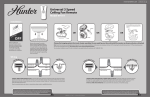
Four Light Fixture
Owner’s Guide and Installation Manual
Manual De Propietario
English
Español
Form# 43553-01
20090515
©2009 Hunter Fan Co.
Welcome
For Your Records and
Warranty Assistance
For reference, also attach your receipt or a copy
of your receipt to the manual.
Your new Hunter® light fixture is an addition to your home or office
that will provide comfort and performance for many years. This
installation and operation manual gives you complete instructions for
installing and operating your light fixture.
__________________________________________
Model Name
We are proud of our work. We appreciate the opportunity to supply
you with the best products available anywhere in the world.
__________________________________________
Model No.
Before installing your light fixture, for your records and warranty
assistance, record information from the carton and Hunter nameplate
label.
__________________________________________
Date Purchased
__________________________________________
Where Purchased
Table Of Contents
1 • Installing the Light fixture on Fans With
Removable Switch Housings . . . . . . . 4
2 • Installing the Light fixture on Fans With
Non-Removable Switch Housings . . 6
3 • Installing the Light fixture on the Hunter
Originals . . . . . . . . . . . . . . . . . . . . . . . . . . 8
4 • Installing Bulbs and Shades . . . . . . . . . . 9
5 • Troubleshooting . . . . . . . . . . . . . . . . . . . . 10
Cautions and Warnings
• READ THIS ENTIRE MANUAL CAREFULLY BEFORE BEGINNING
INSTALLATION. SAVE THESE INSTRUCTIONS.
• Use only Hunter replacement parts.
• To reduce the risk of personal injury, install this light fixture only on
Hunter® fan types A through Z. Note: The fan type can be found on
the ceiling fan package or on the nameplate label located on top of
the motor housing of the ceiling fan.
• To avoid possible electrical shock, before installing light fixtures,
disconnect the power by turning off the circuit breakers both to
the outlet box and to its associated wall switch location. If you
cannot lock the circuit breakers in the off position, securely fasten a
prominent warning device, such as a tag, to the service panel.
• Connect house wiring to the fan before attaching the light fixture to
the fan.
• All wiring must be in accordance with national and local electrical
codes and ANSI/NFPA 70. If you are unfamiliar with wiring, use a
qualified electrician.
© 2009 Hunter Fan Company
2
43553-01 • 05/15/09 • Hunter Fan Company
Installation Methods of Hunter® Ceiling Fans Type A-Z
Your
® light fixture can be installed in one of three
ways, depending on the type of switch housing. The steps
in this manual include instructions for all three installation
methods: Fans with removeable switch housings, fans
with non-removeable switch housings, and
The Hunter Original.
Removable Switch Housing
Preparing the Light Fixture
1.Shades are not included with this light fixture. Be sure to
purchase shades for your light fixture before installing
this light fixture.
2.Disconnect power by turning off the circuit breakers
both to the outlet box and to its associated wall switch
location.
Non-removable Switch Housing
The Hunter Original
3
43553-01 • 05/15/09 • Hunter Fan Company
1 • Installing the Light fixture on Fans With Removable Switch Housings
1. Unscrew the three screws from the upper switch housing. Disconnect
the 9-pin plug connectors. Remove the lower switch housing.
2. Push the plug button from inside the lower switch housing to remove
the plug button and switch housing cap.
NOTE: Save the plug button and switch housing cap should you
choose to remove the light fixture in the future.
3. Feed the two wires from the light fixture through the center hole in
the lower switch housing.
4. Screw the threaded rod of the light fixture into the center of the lower
switch housing until you feel resistance. Unscrew the light fixture
slightly until the holes of the light fixture are aligned with the holes in
the lower switch housing.
5. Finish attaching the light fixture to the lower switch housing using the
two attachment screws included. Securely tighten the two screws.
6. Install the nut and washer inside the lower switch housing onto the
threaded rod from the upper light housing.
Nut
Washer
Threaded
Rod
Lower
Switch
Housing
Removable Switch Housing
9-Pin Plug
Connector
Screw
Steps 1-2
Lower Switch
Housing
Plug Button
WARNING: Improper installation could
cause the light fixture to fall, or result in
electrical shock or personal injury.
Light
Fixture
Attachment
Screws
Steps 3-6
4
43553-01 • 05/15/09 • Hunter Fan Company
1 • Installing the Light fixture on Fans With Removable Switch Housing (Continued)
7. Remove the wire connectors from the two wires in the switch
housing labeled “Connect Light Here” or “For Light Use.”
To connect the wires, hold the bare metal leads together
and place a wire connector over them, then twist the wire
connector clockwise until tight.
Connect the black wire with a white stripe from the switch
housing to the black wire from the light fixture. Connect the
white wire from the switch housing to the white wire from the
light fixture. Secure all wire connections using wire connectors.
Wires
and Wire
connectors
CAUTION: Be sure no bare metal wires or wire strands are
visible after making the connections.
8. Reconnect the 9-pin plug connector.
9. Reinstall screws to reattach the lower switch housing to the
upper switch housing.
10. Go to the instructions for Installing Bulbs, and Shades.
Step 7
Plug
Connector
Steps 8-9
Lower Switch
Housing
Housing
Assembly Screw
Plug
Connector
Detail
5
43553-01 • 05/15/09 • Hunter Fan Company
2 • Installing the Light fixture on Fans With Non-Removable Switch Housings
1. Uninstall the two attachment screws from the switch housing cover.
2. Remove the plug or screw from the center of the switch housing cover.
3. Thread the switch housing cover onto the light fixture. Align the screw
holes in the light fixture with the screw holes in the switch housing cover.
4. Use the two attachment screws removed from the lower switch housing
and the lock washers on the red tag of the light fixture. Install the screws
into the light fixture and the housing. Securely tighten the two screws.
5. Remove the wire connectors from the two wires in the switch housing
labeled “Connect Light Here” or “For Light Use.” One wire is white and the
other wire is black with a white stripe.
6. Feed the two wires from the switch housing through the threaded rod in
the upper light housing.
7. To connect the wires, hold the bare metal leads together and place a wire
connector over them, then twist the wire connector clockwise until tight.
Connect the black wire with a white stripe from the switch housing to
the black wire from the light fixture. Connect the white wire from the
switch housing to the white wire from the light fixture. Secure all wire
connections using wire connectors.
8. Align the threaded screw holes in the switch housing cover with the
threaded holes in the switch housing. Attach the switch housing cover
and light fixture to the switch
housing using the included
attachment screws.
CAUTION: Be sure no bare
metal wires or wire strands
are visible after making the
connections.
WARNING: Improper
installation could cause
the light fixture to fall.
Non-Removable Switch
Housing
Switch
Housing
Cover
Steps 1-2
Switch
Housing
Cover
Attachment
Screw
Attachment
Plug Screw
Nut
Washer
Screw
Hole
Wires
and Wire
connectors
Step 7
6
43553-01 • 05/15/09 • Hunter Fan Company
Light Fixture
Steps 3-6
2 • Installing the Light fixture on Fans With Non-Removable Switch Housings Cont.
9. Attach the light fixture to the switch housing with the two
screws included with the light fixture, aligning the holes in the
light fixture, switch housing cover, and switch housing.
10. Securely tighten the two screws.
11. Go to the instructions for Installing the Bulbs and Shades.
Wires
and Wire
connectors
Steps 8-9
7
43553-01 • 05/15/09 • Hunter Fan Company
3 • Installing the Light fixture on the Hunter Originals
1. Uninstall the two screws from the switch housing plate.
NOTE: Save the switch housing plate should you choose to remove the
light fixture in the future.
2. Remove the wire connectors from the two wires in the switch housing
labeled “Connect Light Here” or “For Light Use.” One wire is white and the
other wire is black wire with a white stripe. Thread the two wires through
the hole in the center of the light fixture.
3. To connect the wires, hold the bare metal leads together and place a wire
connector over them, then twist the wire connector clockwise until tight.
Connect the black/white striped wire from the switch housing to the black
wire from the light fixture. Connect the white wire from the switch housing
to the white wire from the light fixture. Secure all wire connections using
wire connectors.
CAUTION: Be sure no bare metal wires or wire strands are visible after
making the connections.
4. Attach the light fixture to the switch housing with the two screws,
included with the light fixture, aligning the holes in the fixture, switch
housing cover, and switch housing.
5. Securely tighten the two screws.
6. Go to the instructions for Installing the
Bulbs and Shades.
WARNING: Improper
installation could cause
the light fixture to fall, or
result in electrical shock or
personal injury.
Light
Fixture
Steps 3-6
8
43553-01 • 05/15/09 • Hunter Fan Company
Screw
Switch
Housing
Plate
Wires
and Wire
connectors
4 • Installing Bulbs and Shades
1. Install four purchased shades for the light fixture. For each
light, loosen the three thumbscrews in the shade cup. Place the
shade into the shade cup and tighten the thumbscrews.
2. Install the included CFL light bulbs.
3. The installation is complete and you can restore power to the
ceiling fan.
Thumbscrews
Shade Cup
Steps 1– 3
CFL bulb
(included)
9
43553-01 • 05/15/09 • Hunter Fan Company
5 • Troubleshooting
Troubleshooting
Light does not come on.
1. Make sure bulbs are installed properly.
2. Make sure breakers or fuses are on.
3. Verify that the light power lead is connected at the ceiling. Refer to
your ceiling fan manual for locating assembly and wiring.
Glass rattles.
1. Make sure the glass shades are secure.
If you need parts or service assistance, please call
888‑830‑1326 (In Canada, call 866-268-1936)or
visit us at our Web site at
http://www.hunterfan.com.
Hunter Fan Company
7130 Goodlett Farms Pkwy. # 400
Memphis, Tennessee 38016
This Light Fixture Weighs 4 lbs. 10
43553-01 • 05/15/09 • Hunter Fan Company
Printed in China