1
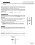
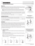
TABLE OF CONTENTS
INSTALLATION PREPARATION………………………………………………………. 2
Parts Supplied……………………………………………………………………. 2
Accessories………………………………………………………………………. 2
Installation Overview……………………………………………………………. 2
Alternative Transducers and Mounting Methods…………………………….. 4
Transducer Exchange…………………………………………………………… 5
INSTALLATION…………………………………………………………………………..
Transom Installation……………………………………………………………..
Inside the Hull Installation……………………………………………………….
Control Head Installation………………………………………………………..
Test the Installation………………………………………………………………
6
6
10
12
15
BEFORE BEGINNING………………………………………………………………….. 16
USING THE LCR400ID …………………………………………………………………
Using the Built-In Simulator…………………………………………………….
Front Panel Buttons……………………………………………………………..
Functions…………………………………………………………………………
18
18
19
20
SPECIFICATIONS……………………………………………………………………… 24
MAINTENANCE AND WARRANTY…………………………………………………..
Maintenance……………………………………………………………………..
Troubleshooting………………………………………………………………….
Warranty………………………………………………………………………….
Service Policy……………………………………………………………………
Customer Support……………………………………………………………….
25
25
26
29
30
31
TRANSDUCER MOUNTING PROCEDURE
Humminbird’s high-speed transducer is supplied with your LCR. This transducer has
been designed to give good high speed readings on most all boat designs, including
aluminum.
Please carefully consider the following before installing your transducer.
TRANSDUCER MOUNTING OPTIONS
A. Transom Mount- The Humminbird high speed transducer allows the transducer
element to be mounted below the bottom of the boat hull keeping the transducer out
of turbulent water and insuring good high speed operation. The transducer will
absorb the blow of any obstruction by rotating up out of the metal spring bracket
without harming the transducer, or your boat. The transducer can be re-engaged by
simply rotating the transducer down and snapping it back in place. (See Figure A)
B. Inside Hull Mount- The high speed transducer can be mounted inside the hull
(without pivot assembly) using the proper two-part epoxy, such as Humminbird’s
epoxy kit. Even though there is some loss of signal in shooting through the hull, your
LCR will perform well with this type of installation. You cannot shoot through the hull
of an aluminum boat.
C. Trolling motor Mount- This type of transducer is not supplied with your LCR. It is
designed to mount on the foot of a trolling motor. You may exchange your un-used
high speed transducer for a trolling motor transducer. Call the Humminbird
Customer Service Department.
D. Bronz Thru-Hull Mount- This transducer is not supplied with your LCR but for an
additional cost you may exchange your un-used high speed transducer for a bronz
thru-hull. The bronz thru-hull transducer has a threaded stem which installs through
a hole drilled in the boat hull, leaving the housing exposed under the boat. This type
of installation must be used for many boats with in-board engines, because there is
no suitable location on the transom away from the noise and turbulence created by
the prop. A bronz thru-hull transducer should be installed by qualified personnel
only.
The LCR will operate well at high speeds with a properly mounted transducer.
Remember, a transducer will not work transmitting through air or through air
bubbles.
1. TRANSOM MOUNTING PROCEDURE
Step 1.
MOUNTING LOCATION- It is important that the transducer be mounted on the transom
where water flow is in constant contact with the transducer. You may wish to observe
the rear of the boat while it is moving through the water to determine the best mounting
location.
Step 2.
BRACKET INSTALLATION (Aluminum Boats)- To install the metal bracket on an
aluminum boat locate the template on the transom between rows of rivets, or ribs that
are on the bottom of the boat. Align the template so that the bottom corner of the
template nearest the center of the transom is on the bottom edge of the transom.
Once the location is determined mark and drill three 7/64” dia.. holes noted on the
template. Attach the metal bracket using three #10 self threading screws supplied. Be
sure to align holes in the center of the
Bracket slots. On some aluminum boats it may be necessary to use a wood back-up
plate. It is important to use a silicone sealant between the screwhead and bracket in
order to prevent leaking. (See Figure C)
Step 2.
BRACKET INSTALLATION (Fiberglass Boats)- If your boat has a stepped transom
located below and under the main transom, the compact transducer design allows
mounting in this area. This mounting location is recommended for good reading at very
high speeds. (See Figure D)
To install the metal bracket on a fiberglass boat, locate the template on the transom in
the same manner as for an aluminum boat. (See Figure C)
NOTE: On boats with more than 15 degree deadrise angle it may be necessary to
mount the transducer slightly off parallel with the water level. (See Figure E)
Mark and drill the three 9/64” dia. holes as shown on the template. Attach the metal
bracket using the three #10 self threading screws supplied. Be sure to align the holes so
that they are centered vertically in the three slots found in the bracket. It is important to
use a silicone sealant between the screwhead and bracket in order to prevent leaking.
Step 3.
TRANSDUCER PIVOT ASSEMBLY- Assemble the pivot to the transducer main body
using the two ¼”x5/8” allen head screws, two 3/8” tooth washers and two, ¼” square
nuts. Make sure the tooth washers are sandwiched between the transducer main body
and the pivot. The square nuts are trapped inside the pivot and will not rotate as the
allen head screws are tightened. HOWEVER, DO NOT TIGHTEN AT THIS POINT.
(See Figure F)
Step 4
TRANSDUCER ASSEMBLY- Insert the transducer assembly into the metal bracket
from the bottom. Push up until the holes in the plastic pivot align with the uppermost
holes in the bracket. Slide the O-ring on to the headed pin and insert it through the two
parts. Assemble by screwing the ¼”x3/8” allen head screw into the end of the pin and
tighten. (See Figure G)
Step 5
ANGLE ALLIGHMENT- Set the transducer angle so that it is parallel with the bottom of
the boat hull. Once proper alignment is achieved, tighten the two allen head screws
using the 5/32” allen wrench provided. The screws are visible through the access holes
on each side of the metal bracket. Check to make sure the transducer main body is
rigidly fastened to the pivot. (See Figure H)
Step 6
CHECK POSITION OF TRANSDUCER- At this point, check to see that the bottom of
the transducer is a minimum of ¼” below the bottom of the transom. (However, as noted
in STEP 2, the top of the transducer cannot fall below the bottom of the transom). If it is
not, remove the transducer assembly from the metal bracket by removing the pin
installed during STEP 3. Loosen the metal bracket mounting screws, re-position the
bracket utilizing it’s slotted holes, tighten and re-assemble. It may be necessary to
replace the silicone sealant after this adjustment is made.
NOTE: It may be necessary to make several high speed runs to adjust transducer
either UP/DOWN or to re-adjust the angle to achieve optimum results.
Step 7
CABLE CLAMPS- Install cable clamps as necessary by drilling a 1/8” dia. hole for the #
8 screw supplied.
2. INSIDE HULL MOUNTING PROCEDURE
Warning: In order to achieve proper results with this type installation, it is important that
the transducer be mounted by someone familiar with the use of two part epoxy
adhesives. For this reason, Techsonic Industries, Inc. will not be responsible for any
damage due to the mounting of your transducer in this manner.
NOTE: An Epoxy Kit (Part N. EPK) is available from Humminbird. This Epoxy Kit has
been formulated for Inside Hull Transducer Installation.
1. Select as flat an area as possible near the aft end and center of boat where the hull
is thin and not double. If the bottom has a runner down the center of boat, select an
area to one side of the runner, but as close to the runner as possible.
2. Clean the inside of the boat with lacquer thinner in the area transducer is to be
mounted. Outside of boat in this area should also be cleaned. (Not with lacquer
thinner).
3. Put approximately one inch of water in the bottom of the boat.
4. Put transducer in the water. The bottom of the transducer should be in a flat area
and should be in good contact with the bottom of the boat.
5. Operate the LCR with the boat operating at high speed. The transducer may have to
be moved in order to find an area where satisfactory operation is observed.
6. When an area is found that produces satisfactory operation, mark the location of the
transducer.
7. Remove the water and transducer and clean the marked area and the bottom of the
transducer thoroughly.
8. Using the Humminbird Epoxy Kit or equivalent, mix an ample amount of epoxy
without causing it to bubble and pour it in the area the transducer is to be mounted.
The puddle should be larger than the bottom of the transducer.
9. Coat the bottom of the transducer with epoxy, then put it in the center of the puddle
and push down on the transducer while moving it around in a circular motion. This
forces out any air bubbles that may be trapped between the bottom of the transducer
and the hull of the boat.
10. Let epoxy cure then the transducer is ready to operate. No water is now required in
the bottom of the boat and gas and oil that is spilled inside of the boat will not
degrade performance as it will if the transducer is placed only in water.
CAUTION: Do not use the silicone seal or any soft adhesive to bond the transducer
to the hull. This will reduce the sensitivity of the unit.
CAUTIONS
1. Occasionally the “eye“ of your transducer may become dirty from storage or from
contact with oils present in boats or marina environments. (Oil will cause the “eye” to
lose the intimate contact with the water which is necessary for efficient operation.)
The “eye” may be cleaned with liquid detergent.
2. Improper installation of the transducer can alter the efficiency and accuracy of the
entire system.
3. If your boat of transducer is out of the water for a period of time, it may take a short
period of time for the transducer to become thoroughly “wetted” when returned to the
water. Also, re-entry may cause turbulence, which will create air bubbles in the “eye”
of the transducer. The bubbles will disappear in a short time or can be removed by
rubbing the transducer “eye” with your fingers while the transducer is in the water.
4. If your instrument should fail to function, be sure to check all the electrical
connections before removing the transducer or calling a serviceman.
5. Inspect your transducer cable and make sure that it has not been cut or damaged to
the point where it will affect the performance of the transducer. A slight nick or cut,
exposing the outer cable, can be repaired by wrapping with electrical tape. A
transducer can be damaged if the inner cable and outer cable are allowed to make
contact. Such a problem can sometimes be corrected by properly splicing the
coaxial cable. This should only be attempted by a qualified service technician.
6. If your LCR is not working properly and you suspect the problem might be in your
transducer, we would recommend you borrow a unit from a friend and try it on your
boat. If the symptoms are the same, you can almost be certain that the problem is in
the transducer.
INSTALLING THE LCR
The LCR should be mounted on a flat, solid surface for maximum stability. The low
profile swivel mount has four holes drilled in the base. It is recommended that all four
holes be used.
Position the swivel base and drill four ¼” diameter holes. Note: The LCR hole pattern Is
the same as for all Humminbird flasher units. Use hardware provided to mount this base
to the boat.
Next place the gimbal bracket on the swivel base and attach with four small machine
screws, provided.
Place the LCR in the gimbal mount and make certain the rubber washers provided are
placed between the unit and the gimbal bracket Important: Note which side of the
gimbal faces forward. (Slots on gimbal bracket go towards rear). Also, rubber washer
must be located between the unit and the gimbal bracket.
Install the mounting knobs and tighten snugly. The unit can now be swiveled and tilted
to any desired position.
OTHER MOUNTING OPTIONS
1. The LCR gimbal bracket can also be mounted on the SM-4, quick disconnect swivel
mount.
2. The LCR gimbal bracket can also be mounted directly to the dash without the swivel
mount, however, this method is not recommended since the unit cannot be rotated.
INSTALLING THE CABLES
Your LCR comes equipped with Humminbird’s new Angle-Lock power and transducer
connectors. The power connector is identified with the letter P on the back of the plug.
It plugs into the outlet on the back of the unit marked “Power”. The transducer connector
is identified with the letter T and plugs into the outlet on the back of the unit marked
“Transducer”. Note: An adapter (AD-4) is available to allow use of an old waterproof
(BNC) transducer with the LCR, but be sure that the transducer is a 16degree. A 32degree transducer cannot be used.
A 11/8” hole must be drilled to pull through the transducer connector. After drilling the
hole, pull the transducer connector up through the hole. If you are installing two units,
both transducer connectors can be pulled through this 1 1/8” inch hole. Next, push the
power cable wires down through the hole. A hole cover has been provided which will
dress and hold the wires. Install the hole cover after determining the necessary wire
length from the hole.
The power cable has a red lead to the positive (+) post and the black lead to the
negative (-) post. Install a 1 amp fuse between the red cable and positive post of your
12-volt battery.
If a fuse panel is available, we recommend wiring the power cable into the fuse panel.
Note: The LCR must be fused separately from any other accessory.
Your Angle-Lock connectors can only be plugged in one way. Position the connector so
the letter P or T can be read and the 90 degree bend is pointed downward. Push the
connector in as far as it will go. Turn the positive locking ring as far as it will go
clockwise until you feel it lock. Locking ring as far as it will go clockwise until you feel it
lock. Your connector is now locked into place.
Note: For easy access to the connectors, simply loosen the mounting knobs and tilt your
LCR forward. The connectors are now in full view and easy to plug or unplug.
BEFORE BEGINNING
HOW THE LCR400ID WORKS
HOW THE LCR400ID WORKS
There are two main components to an LCR400ID installation: The transducer, which
you will install on the transom or inside the hull, and the LCR 400ID unit which you will
mount with the supplied gimbal bracket. The transducer and LCR 400ID communicate
by means of a cable, and are powered by your boat’s 12-volt DC battery.
The transducer and LCR 400ID use the basic principles of sonar to reveal objects
beneath the water's surface. The LCR 400ID continuously sends electronic signals to
the transducer, which converts them to ultrasonic signals that it aims toward the bottom.
Each signal travels downward until it strikes an object or the bottom, then immediately
echoes back to the transducer. As the transducer receives these signals, it converts
them back to electronic signals for display on the LCR400ID screen.
The LCR 400ID uses the returned
signals to display a detailed underwater
image, and constantly updates the
display as you travel across the water.
The display informs you of the current
depth and reveals individual fish,
schools of fish, their location, and
bottom details.
Easy-to-use controls on the LCR 400ID
allow you to set the depth range, adjust
display speed and sensitivity, enable a
fish alarm and bottom alarm, and
display a "zoom" window of still more
detailed information.
BEFORE BEGINNING
THE HUMMINBIRD ADVANTAGE
THE HUMMINBIRD ADVANTAGE
The LCR 400ID incorporates the best of available technologies, and offers advantages
you won’t find in other depth sounders.
The liquid crystal display (LCD) offers sharp viewing even in bright, direct sunlight, and
is continuously lit for nighttime operation. Advanced LCD “super-twist” technology built
into the LCR 400ID offers a wider viewing angle and higher contrast than ordinary LCD
screens.
(You will notice that the display can be seen better at certain angles. The gimbal
mounting bracket lets you easily adjust the viewing angle for optimum viewing. Note
also that some polarized glasses can affect your viewing by causing a rainbow or prism
to appear; if so, tilt the unit slightly.)
Though it includes sophisticated electronics, the LCR 400ID is tough enough to take the
pounding punishment of rough seas or a race across the lake. Completely waterproof –
even saltwater-proof – your LCR 400ID will provide you with many years of thoroughly
reliable operation.
In the unlikely event that your Humminbird does require repairs, we offer an exclusive
Service Guarantee – free of charge during the first year after purchase, and available at
a reasonable rate after the one-year warranty period. Complete details are included in
this manual.
USING THE LCR400ID
USING THE BUILT-IN SIMULATOR
USING THE LCR400ID
This section provides complete
information on operating the LCR 400ID
through its front panel controls. You are
encouraged to read this information
completely as you first learn to use the
LCR 400ID. Doing so will ensure you
make the most of its many features and
functions.
The first part of this section explains the
use of the built-in practice simulator,
which you can use to practice selecting
functions through the front panel. The
remaining instructions, which can be
followed while using the simulator or in actual operation, explain each function and are
organized according to the front panel layout.
USING THE BUILT-IN SIMULATOR
The LCR 400ID includes a built-in simulator that helps you learn to use your new
equipment. The simulator displays a typical underwater scene, and lets you practice
with the controls.
The unit must be turned off before you start the simulator. To activate it, press down
and hold the POWER button until a chirping sound begins. Release the button, and the
built-in simulator begins displaying a typical LCR 400ID reading.
You can use the simulator to learn the functions explained in the following pages, just
as if you were getting actual on-the-water readings (but note that “Sensitivity” is
disabled). To turn off the simulator, turn off the unit by pressing the POWER button
again.
Of course, the best way to learn the LCR 400ID is with actual use, especially in familiar
waters. If you know what’s below and see it on-screen, you’ll quickly become an LCR
400ID expert.
USING THE LCR400ID
OPERATING THE LCR400ID
FRONT PANEL BUTTONS
The LCR 400ID offers several functions that you can adjust with the
front panel buttons. (Note that to select something with a button, you
must press it fully so that you hear a “chirp” sound).
You can get acquainted with these features by actual operation, or
when using the simulator.
POWER: Press this once to turn the LCR 400ID on. Pressing it again
turns the LCR 400ID off. (Any adjustments you make with the other
front panel buttons are retained, as long as the 12-volt DC power
supply remains connected). When the unit is off, keeping POWER
pressed for about 2 seconds starts the built-in simulator.
STOP: Press this to “freeze” the display so you can study it. Press it
again to restart the display movement.
SELECT: This button is used to access the following functions for further adjustments:
•
•
•
•
•
•
•
•
Sensitivity/Units
Bottom Alarm
Fish Alarm
Zoom
Bottom Lock
Display Speed
Depth Range
Fish ID
To adjust any of these, press SELECT until the function you want appears. Each
function’s display tells you how to use the arrow buttons and ON/OFF for adjustment;
when first learning, you should also refer to the following instructions.
After you adjust any function, the display returns to its full-screen reading.
NOTE: The last function you select remains “active” – that is, you can adjust it
without having to press SELECT again. You can use this to simplify operations.
For example, if the bottom alarm is the last function used, you can readjust the alarm by
pressing one of the arrow buttons. Or, if you often use Zoom, you can select it once,
then switch it on and off by simply pressing ON-OFF.
The following sections describe each function, in order os appearance as you first press
SELECT.
USING THE LCR400ID
OPERATING THE LCR400ID
SENSITIVITY
1. Selecting Sensitivity/Units;
Factory setting: +0/FEET
The Sensitivity/Units function has two uses: It lets you
adjust LCR 400ID sensitivity and controls whether depth
measurement is in feet or fathoms.
The LCR 400ID automatically increases or decreases its
sensitivity setting when water conditions change (as
when the bottom is stirred up). If you want to manually
adjust Sensitivity, select SENS and press the Up or Down
arrow button to adjust the automatic setting with a “+5” to
“-5” range. For example, if you set it at “+2”, Sensitivity
remains 2 settings higher than the normal automatic
setting.
Pressing the ON-OFF button when the SENS menu is
displayed switches the unit of depth measurement
between feet and fathoms.
BOTTOM ALARM
2. Enabling Bottom Alarm;
Factory Setting: OFF
The Bottom Alarm lets you specify the minimum depth
you want to maintain. To use it, select B ALM; then
press the ON-OFF button to activate the alarm, and the
Up or Down arrow key to adjust the depth at which the
alarm will sound. An alarm symbol is displayed when
this function is on.
When Bottom Alarm is on, you’ll hear a continuous
chirping sound when the bottom is shallower than you
defined. This is very handy for alerting you to shallow
water or helping you to maintain position over structure.
USING THE LCR400ID
OPERATING THE LCR400ID
FISH ALARM
3. Enabling Fish Alarm;
Factory Setting: OFF
The Fish Alarm alerts you with a chirping sound
whenever the LCR 400ID detects fish (or another object
not attached to the bottom). To activate it, select FISH
ALM and press the ON-OFF button. A fish symbol
reminds you that the alarm is on.
ZOOM
4. Using Zoom;
Factory Setting: OFF
Zoom provides an up-close view. To activate it, select
Zoom and press ON-OFF. The Zoom view initially
begins at the surface; pressing the Up or Down arrow
adjust the Zoom depth. The range of the display is
shown when the Zoom is on.
The Zoom range depends on the current Depth Range:
7 ½’ in the 15’ and 30’ Depth Ranges, 15’ in the 60’ and
120’ Depth Ranges, and 30’ in the 180’ to 600’ Depth
Ranges.
Remember: If Zoom is the last function selected, you
can use the arrow button to adjust the Zoom depth or
ON-OFF to switch Zoom on and off without having to
press SELECT first.
USING THE LCR400ID
OPERATING THE LCR400ID
BOTTOM LOCK
5. Using Bottom-Lock;
Factory Setting: OFF
Bottom-lock provides an up-close view like Zoom, except
that in this case the zoomed view automatically moves
up or down to stay on the bottom. To use this feature,
select BTM LOCK and press ON-OFF. The range of the
display is shown when Bottom-Lock is on.
This is an ideal feature for finding structure or Iocating
fish near the bottom.
Remember: If Bottom-Lock is the last function selected,
you can use the ON-OFF button to switch Bottom-Lock
on and off without having to press SELECT first.
DISPLAY SPEED
6. Setting Display Speed;
Factory Setting: One level below maximum
The LCR 400ID display is “updated” (advances across
the screen) as you move through the water. The speed
at which the display is updated depends on the Display
Speed setting. To adjust it, select SPEED, and press
the Up arrow for a faster setting or the Down arrow for a
slower setting.
In general, higher Display Speed settings provide faster
updates, while slower Display Speeds provide more
detailed information.
USING THE LCR400ID
OPERATING THE LCR400ID
DEPTH RANGE
7. Setting Depth Range;
Factory Setting: On (Automatic)
When you turn the LCR 400ID on, it finds the bottom,
sets the ideal depth range, and automatically adjusts
the depth range (to as much as 480’) as the depth
changes. In this “Auto Depth Range” mode, the bottom
is blacked-in for easy-to-understand readings.
If you prefer, you can turn Auto Depth Range off.
Select RANGE, press ON-OFF, and adjust the Depth
Range with the Up or Down arrow key. You can set
the Depth Range up to 600’.
In this “Manual Depth Range” mode, the bottom is not
blacked in. This lets you see a “second return,” which
is preferred by some fishermen because the width of
the second echo can indicate bottom hardness.
FISH ID
8. Selecting Fish ID;
Factory Setting: On (Automatic)
When you turn the LCR 400ID on, the unit
automatically sets Fish ID to the On position. To turn
the ID feature off, and display fish with pixels instead
of the ID icons, press the ON-OFF button while within
the Fish ID menu. Pressing the ON-OFF button again
reactivates the ID function.
SPECIFICATIONS
Operating Frequency
200 KHz
Power Requirements
10-16 Volts
Power Cable Length
Standard Unit
48”
Portable Unit
Non-replaceable
Transducer:
Standard
XHS-6-16
Portable
XPT-6-16
Transducer Cone Angle
16 degrees
Depth Ranges
0 to 15’, 30’, 60’, 120’, 180’, 240’, 360’, or 480’ (plus 0600’ in manual mode)
Zoom Ranges
7½’, 15’, 30’
Unit Construction
High-impact Polycarbonate housing
Unit Dimensions
6”W X 4¾”H X 2”D
Display
Super-twist liquid crystal
Viewing Area
2 7/16” W X 2 5/8” H
Matrix Configuration
32 X 46 pixels
MAINTENANCE AND WARRANTY
MAINTENANCE
MAINTENANCE
Your Humminbird fishfinder is designed to provide years of trouble free operation with
virtually no maintenance. Follow these simple procedures to ensure your Humminbird
continues to deliver top performance.
•
If the unit comes into contact with salt spray simply wipe the affected surfaces with a
cloth dampened in fresh water. Do not use a chemical glass cleaner on the lens.
Chemicals in the solution may cause cracking in the lens of the unit.
•
When cleaning the LCD protective lens, use a chamois and non-abrasive, mild
cleaner. Do not wipe while dirt or grease is on the lens. Be careful to avoid
scratching the lens.
•
If your boat remains in the water for long periods of time, algae and other marine
growth can reduce the effectiveness of the transducer. Periodically clean the face of
the transducer with liquid detergent. Pivoting the transducer up in the bracket may
allow better access for inspection or cleaning.
•
If your boat remains out of the water for a long period of time, it may take some time
to wet the transducer when returned to the water. Small air bubbles can climb to the
surface of the transducer and interfere with proper operation. These bubbles
dissipate with time, or you can wipe the face of the transducer with your fingers after
the transducer is in the water.
•
Never leave the fishfinder in a closed car or trunk - the extremely high temperatures
generated in hot weather can damage the electronics.
MAINTENANCE AND WARRANTY
TROUBLESHOOTING
TROUBLESHOOTING
Do not attempt to repair the fishfinder yourself. There are no user serviceable parts
inside, and special tools and techniques are required for reassembly to ensure the
waterproof integrity of the housing. Repairs should be performed only by authorized
Humminbird technicians.
Many requests for repair received by Humminbird involve units that do not actually reed
repair. These units are returned “no problem found.” If you have a problem with your
Humminbird, use the following troubleshooting guide before calling Customer Support
or sending your unit in for repair. Your Humminbird fishfinder contains several tools that
can aid in determining if there is a problem and how to isolate and repair the problem in
many cases.
1. Nothing happens when I turn the unit on.
Check the power cable connection at both ends. Be sure the cable is connected
correctly to a reliable power source - red lead to positive, black lead to negative or
ground. Ensure the power available at the mount is between 10 and 20 VDC. If the unit
is wired through a fuse panel, ensure the panel is powered. Often accessory fuse
panels are controlled by a separate switch or the ignition switch. Also, often a fuse can
appear to be good when in fact it is not. Check the fuse with a tester or replace it with a
fuse known to be good.
Check the power connection to the unit. It is possible to force the power cable connector
into the cable holder incorrectly. If the connector is reversed, the unit will not work.
Examine the contacts on the back of the unit to ensure there is no corrosion. Finally,
ensure the unit is firmly seated on the mount. The electrical contacts are not made until
the unit is fully seated.
Ensure the metal cable retainer is properly installed in the mount. If not, the power
connected may push out when the unit is put on the mount.
2. There is no transducer detected.
Most Humminbird fishfinders have the ability to detect and identify that a transducer is
connected. If at power up, a message indicates "transducer not connected,” only
simulator operation is possible. First, ensure that an appropriate transducer connector is
positioned correctly in the connector holder, and that the unit is fully seated on the
mount. Your Humminbird fishfinder will work only with an appropriate transducer; check
the accessory guide for compatibility.
MAINTENANCE AND WARRANTY
TROUBLESHOOTING
Second, inspect the transducer cable from end to end for breaks, kinks, or cuts in the
outer casing of the cable. Also ensure the transducer is fully submerged in water. If the
transducer is connected to the unit through a switch, temporarily connect it directly to
the unit and try again. If none of these items identifies an obvious problem, the
transducer itself is probably the problem. Be sure to include the transducer if returning
the unit for repair.
3. There is no bottom reading visible on the display.
There are a number of possible causes for this condition. If the loss of bottom
information occurs only at high boat speeds, the transducer needs adjusting. If the
digital depth readout is working but there is no bottom visible on-screen, it is possible
the depth range has been adjusted manually to a range lower than what is needed to
display the bottom. Also, in very deep water, it may be necessary to manually increase
the sensitivity setting to maintain a graphic depiction of the bottom.
If you are using a transducer switch to connect two transducers to the unit, ensure the
switch is in the correct position to connect a transducer that is in water. (If a trolling
motor transducer is selected and the trolling motor is out of water, no sonar information
appears.)
It none of the above solve the problem, inspect the transducer cable from end to end for
breaks, kinks, or cuts in the outer casing of the cable. If the transducer is connected to
the unit through a switch, temporarily connect it directly to the unit and try again. If none
of these items identifies an obvious problem, the transducer itself may be the problem.
Be sure to include the transducer if returning the unit for repair.
4. When in very shallow water, I get gaps in the bottom reading and inconsistent
digital depth indication.
Your Humminbird fishfinder will work reliably in water 2’ (.6m) or deeper. The depth is
measured from the transducer, not necessarily from the surface.
MAINTENANCE AND WARRANTY
TROUBLESHOOTING
5. The unit comes on before I press POWER, and won't turn off.
Check the transducer cable. If the outer jacket of the cable has been cut and the cable
is in contact with bare metal, you need to repair the cut with electrical tape. If there is no
problem with the cable, disconnect the transducer from the unit and see if the problem
is corrected, to confirm the source of the problem.
6. I get gaps in the reading at high speeds.
Your transducer needs adjusting. If the transducer is transom-mounted, there are two
adjustments available to you - height and running angle. Make small adjustments and
run the boat at high speeds to determine the effect. It may take several tries to optimize
high speed operation. This can also be a result of air or turbulence in the transducer
location caused by rivets, ribs, etc.
7. My unit loses power at high speeds.
Most Humminbird fishfinders have over-voltage protection that turns the unit off when
input voltage exceeds 20 VDC. Some outboard motors do not effectively regulate the
power output of the engine's alternator and can produce voltage in excess of 20 volts
when running at high RPMs. Your fishfinder displays input voltage in the Diagnostic
screen. Use this readout to determine if the voltage exceeds 20 VDC.
8. The screen begins to fadeout. Images are not as sharp as normal.
Check the input voltage using Diagnostic. The fishfinder will not operate on input
voltages below 10 VDC.
9. The display shows many black dots at high speeds and high sensitivity
settings.
You are seeing noise or interference caused by one of several sources. Noise can be
caused by other electronic devices. Turn off any nearby electronics and see if the
problem goes away. Noise can also be caused by the engine. If engine noise is causing
the interference, the problem will intensify at higher RPMs. Increase the engine speed
with the boat stationary to isolate this cause. Propeller cavitation can appear as noise
on-screen. If the transducer is mounted too close to the propeller, the turbulence
generated can interfere with the sonar signal. Ensure that the transducer is mounted at
least 15" (38cm) from the prop.
MAINTENANCE AND WARRANTY
WARRANTY
HUMMINBIRD ONE YEAR FULL WARRANTY
First year repairs (from original date of purchase) on your Humminbird fishfinder are
absolutely free. This does not include physical damage to the unit or its accessory
items. Any modification or attempt to repair the original equipment or accessories by
unauthorized individuals will void the warranty. Return the warranty registration card
and retain your bill of sale for warranty verification. Accessories not manufactured under
the Humminbird trade name are not covered by our warranty. The customer is
responsible for shipping charges to Humminbird. Humminbird will provide ground
UPS or Parcel Post shipping back to the customer free of charge. This warranty applies
to the original purchaser only.
This warranty is in lieu of all other warranties expressed or implied and no
representatives or persons are authorized to provide for any other liability in connection
with the sale of our products. Humminbird reserves the right to perform modifications or
improvement on its products without incurring the obligation to install the changes on
units previously manufactured, sold, delivered, or serviced.
THIS IS A FULL WARRANTY AS DEFINED BY THE FEDERAL WARRANTY ACT
EFFECTIVE JULY 4 1975.
MAINTENANCE AND WARRANTY
SERVICE POLICY
SERVICE POLICY
This Service Policy is valid in the United States only. This applies to Humminbird units
returned to our factory in Eufaula, Alabama, and is subject to change without notice.
All repair work is performed by factory-trained technicians to meet exacting factory
specifications. Factory serviced units go through the same rigorous testing and quality
control inspection as new production units.
Even though you'll probably never need to take advantage of our incredible service
guarantee, it’s good to know that we back our unit this well. We do it because you
deserve the best. We will make every effort to repair your unit within three working days
from the receipt of your unit. This does not include shipping time to and from our factory.
Units received on Friday are usually shipped by Wednesday, units received Monday are
usually shipped by Thursday, etc.
We reserve the right to deem any product unserviceable when replacement parts are no
longer reasonably available or impossible to obtain.
After the original warranty period, a standard flat rate service charge will be assessed
for each repair (physical damage and missing parts are not included). Please call our
Customer Support Department to verify the service charge for your unit.
The standard service charge includes UPS or Parcel Post freight only. If charges are
not prepaid, the unit will be returned COD. If you are experiencing problems related to
bottom or depth readings please send your transducer along with your unit when
sending for repair.
MAINTENANCE AND WARRANTY
CUSTOMER SUPPORT
CUSTOMER SUPPORT
If you have any questions, call our
Humminbird Customer Support Hotline: 1-334-687-0503
Throughout the U.S. and Canada, hours are Monday-Friday, 8:00 a.m. to 5:00 p.m.
Central time.
If after reading “Troubleshooting” you determine your unit needs factory service, please
attach a description of the problem and send it with the unit to the address below.
If you are including a check please attach it to the unit.
Humminbird
Service Department
Three Humminbird Lane
Eufaula, AL 36027
USA