1
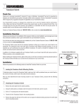
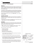
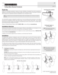
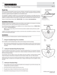
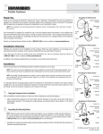
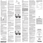
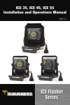
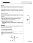
1
530516-1_D
Quick Disconnect Mounting Bracket
Thank You
Thank you for choosing Humminbird®, America's #1 name in fishfinders. Humminbird® has built its reputation
by designing and manufacturing top-quality, thoroughly reliable marine equipment. Genuine Humminbird®
accessories offer the opportunity to upgrade and expand the capabilities of your Humminbird® product.
Your Humminbird® accessory is designed for trouble-free use in even the harshest marine environment.
In the unlikely event that your Humminbird® accessory does require repairs, we offer an exclusive Service
Policy - free of charge during the first year after purchase, and available at a reasonable rate after the
one-year period. For complete details, see the Warranty section included in this manual.
Contact our Customer Resource Center at 1-800-633-1468 or visit our website at www.humminbird.com.
Installation Overview
Following are instructions for the installation of this accessory. Before you start installation, we encourage
you to read these instructions carefully in order to get the full benefit from your Humminbird® accessory.
If you find that any items are missing from your installation kit, call our Customer Resource Center at
1-800-633-1468 or visit our website at www.humminbird.com.
To install your Quick Disconnect mounting system, you will need a drill, your control head, the mounting
bracket, the connector holder, the power cable, the mounting hardware, a 9/64" drill bit, a 1" hole saw, a
Phillips and a flat-head screw driver, an adjustable wrench, a level, and marine-grade silicone sealant.
Installation
Perform the procedures in the following sections to install the Wide Quick Disconnect mounting system on
your boat.
360 Degree Swivel
1. Determine Where to Mount
Begin the installation by determining where to mount the control head. Consider the following to determine
the best location:
• To check the location planned for the control head, test run the cables for power, transducer and
Temp/Speed accessory (if applicable).
• There are two ways to route the cables to the unit: through a hole in the mounting surface underneath
the mounting bracket, or from a hole outside the mounting bracket. Routing the cables under the
mounting bracket provides maximum weather protection; this may not be feasible, however, if the area
under the control head is inaccessible. In this case, route the cables through a hole at another location
and cover with the supplied hole cover.
90 Degree Tilt
• The mounting surface should be stable enough to protect the control head from excessive wave shock
and vibration, and should provide visibility while in operation.
• The mounting area should allow sufficient room for the unit to pivot and swivel freely, and for easy
removal and installation (see illustrations).
© 2008 Humminbird®, Eufaula AL, USA.
All rights reserved.
2
530516-1_D
Quick Disconnect Mounting Bracket
2. Drilling the Mounting Holes
Route the Cables
Through the Mounting Bracket
1. Set the mounting bracket in place on the mounting surface. Mark the four mounting screw locations
with a pencil or a punch.
2. Set the mounting bracket aside, and drill the four mounting holes using a 9/64” drill bit. If you have
access to the underside of the mounting surface, mark and drill a 1” hole centered between the four
mounting screw holes.
Cables
Mounting
Bracket
Drilling the Mounting Holes
Mounting
Hole
Locations
Mounting
Hole
Locations
Grommet
Route the Cables Through the Hole
Not Covered By The Mounting Bracket
1" (25 mm) Hole Location
Hole Cover
3. Route the Cables Through the Mounting Bracket
1a. If the cables must pass through a hole directly beneath the mounting bracket, mark and drill an
additional 1" (25 mm) hole centered between the four mounting holes. Route the cables through the
grommet, then press the grommet in place around the cables and into the 1"(25 mm) hole. Pass the
cables out of the top of the mounting bracket.
1b. If the cables cannot be routed directly beneath the mounting bracket, mark and drill a 1" (25 mm) hole
that will allow you to run the cables close to the bracket. Pass the cables through the 1" (25 mm) hole,
through the mounting base, and out of the top of the mounting bracket. Using needle-nose pliers, break
out the tabs on the rear of the mounting base. Place the Hole Cover over the mounting surface hole,
then use it to mark the position of the two mounting screws. Remove the Hole Cover, drill the two
mounting holes using a 9/64" (3.5 mm) bit, fill them with marine-grade silicone, then replace the Hole
Cover and insert the #8 Phillips countersink wood screws. Hand-tighten only.
Removing the Break Out Tabs
NOTE: Remove the break-out tables only if the cable hole is not under the mount.
2. Place the mounting bracket on the mounting surface aligned with the drilled holes and fill the mounting
holes with marine grade silicone. Insert the four #8 Phillips countersink wood screws into the mounting
holes. Hand-tighten only.
CAUTION! Do not cut or shorten the transducer cable, and try not to damage the cable insulation. Route the cable as
far as possible from any VHF radio antenna cables or tachometer cables to reduce the possibility of interference. If the
cable is too short, extension cables are available to extend the transducer cable up to a total of 50'. For assistance,
contact the Customer Resource Center at www.humminbird.com or call 1-800-633-1468 for more information.
Break-out tabs
© 2008 Humminbird®, Eufaula AL, USA.
All rights reserved.
3
530516-1_D
Quick Disconnect Mounting Bracket
4. Connecting the Cable
Cable Connector Holder
Transducer
1. Insert the cable connector into the appropriate slots of the connector holder. The cable connectors are
labeled, and there are corresponding labels on the connector holder on the rear of the fishfinder. The
slots are keyed to prevent reversed installation, so be careful not to force the connector into the holder.
Accessory
Communications
Power
2. Carefully pull the excess cable from beneath the mounting surface so the connector holder aligns with
the mounting holes on the front of the mounting bracket.
3. Snap the support plate to the rear of the connector holder as illustrated.
4. Insert the connector holder into place and use the two #6-32 x 3/4” screws to fasten it to the mounting
bracket.
Snap the Support Plate onto
the Connector Holder
Attach the Connector Holder
to the Mounting Bracket
Connector Holder
Cable Connector
Support
Plate
5. Install the control head by sliding it onto the mounting bracket until it is fully seated. To remove the unit,
simply depress the latch on the rear of the unit and lift.
6. If the cables pass outside the mounting bracket, reinstall the hole cover over the thru-hole and fasten
in place using the two #8 x 7/8” wood screws.
Your fishfinder is now ready for operation.
Firmly Press
Latch to
Remove Unit
© 2008 Humminbird®, Eufaula AL, USA.
All rights reserved.
4
530516-1_D
Quick Disconnect Mounting Bracket
1-Year Limited Warranty
We warrant the original retail purchaser that products made by
Humminbird® have been manufactured free from defects in materials
and workmanship. This warranty is effective for one year from the date
of original retail purchase. Humminbird® products found to be defective
and covered by this warranty will be replaced or repaired free of charge
at Humminbird® option and returned to the customer freight prepaid.
Humminbird® sole responsibility under this warranty is limited to the
repair or replacement of a product that has been deemed defective by
Humminbird®. Humminbird® is not responsible for charges connected
with the removal of such product or reinstallation of replaced or
repaired parts.
This warranty does not apply to a product that has been:
• Improperly installed;
• Used in an installation other than that recommended in the
product installation and operation instructions;
• Damaged or has failed because of an accident or abnormal
operation;
• Repaired or modified by entities other than Humminbird®.
Please retain your original receipt as a proof of the purchase date. This
will be required for in-warranty service.
THIS WARRANTY IS EXPRESSLY IN LIEU OF ANY OTHER WARRANTIES,
OBLIGATIONS OR LIABILITIES ON THE PART OF HUMMINBIRD® AND
WILL BE THE CUSTOMER'S EXCLUSIVE REMEDY, EXCEPT FOR ANY
APPLICABLE IMPLIED WARRANTIES UNDER STATE LAW WHICH ARE
HEREBY LIMITED IN DURATION TO ONE YEAR FROM THE DATE OF
ORIGINAL PURCHASE. IN NO EVENT WILL HUMMINBIRD® BE LIABLE
FOR ANY INCIDENTAL OR CONSEQUENTIAL DAMAGES FOR BREACH OF
ANY EXPRESS OR IMPLIED WARRANTY RELATING TO THE PRODUCTS.
Some states do not allow limitations on an implied warranty, or the
exclusion of incidental or consequential damages, so the above
exclusions may not apply to you. You may also have other rights, which
vary from state to state.
DOMESTIC (USA) CUSTOMERS:
PLEASE DO NOT RETURN THIS PRODUCT TO STORE FOR SERVICE
For all technical issues please call 1-800-633-1468
Or visit www.humminbird.com, click SUPPORT
Please reference product serial number and
model number when contacting Humminbird®.
Contact Humminbird®
Contact the Humminbird® Customer Resource Center
in any of the following ways:
By Telephone
(Monday - Friday 8:00 a.m. to 4:30 p.m. Central Standard Time):
1-800-633-1468
By e-mail
(typically we respond to your e-mail within three business days):
[email protected]
For direct shipping, our address is:
Humminbird
Service Department
678 Humminbird Lane
Eufaula, AL 36027 USA
ENVIRONMENTAL COMPLIANCE STATEMENT: It is the intention of
Humminbird® to be a responsible corporate citizen, operating in compliance
with known and applicable environmental regulations, and a good neighbor in
the communities where we make or sell our products.
WEEE DIRECTIVE: EU Directive 2002/96/EC “Waste of Electrical and
Electronic Equipment Directive (WEEE)” impacts most distributors, sellers, and
manufacturers of consumer electronics in the European Union. The WEEE
Directive requires the producer of consumer electronics to take responsibility for
the management of waste from their products to achieve environmentally
responsible disposal during the product life cycle.
WEEE compliance may not be required in your location for electrical &
electronic equipment (EEE), nor may it be required for EEE designed and
intended as fixed or temporary installation in transportation vehicles such as
automobiles, aircraft, and boats. In some European Union member states, these
vehicles are considered outside of the scope of the Directive, and EEE for those
applications can be considered excluded from the WEEE Directive requirement.
This symbol (WEEE wheelie bin) on product indicates the product must
not be disposed of with other household refuse. It must be disposed of
and collected for recycling and recovery of waste EEE. Humminbird®
will mark all EEE products in accordance with the WEEE Directive. It is
our goal to comply in the collection, treatment, recovery, and environmentally
sound disposal of those products; however, these requirement do vary within
European Union member states. For more information about where you should
dispose of your waste equipment for recycling and recovery and/or your
European Union member state requirements, please contact your dealer or
distributor from which your product was purchased.
© 2008 Humminbird®, Eufaula AL, USA.
All rights reserved.