1
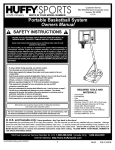
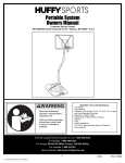
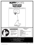
A Huffy Company
Customer Service Center
N53 W24700 South Corporate Circle
Sussex, WI 53089
U.S.A.
WRITE IN YOUR MODEL NUMBER:___________
Portable Basketball System
Owners Manual
SAFETY INSTRUCTIONS
FAILURE TO FOLLOW THESE SAFETY INSTRUCTIONS MAY RESULT IN
SERIOUS INJURY, PROPERTY DAMAGE AND WILL VOID WARRANTY.
Owner must ensure that all players know and follow these rules for safe
operation of the system.
To ensure safety, do not attempt to assemble this system without following the
instructions carefully. Proper and complete assembly, use and supervision is
essential for proper operation and to reduce the risk of accident or injury. A high
probability of serious injury exists if this system is not installed, maintained, and
operated properly. Check entire box and inside all packing material for parts
and/or additional instructional material. Before beginning assembly, read the
instructions and identify parts using the hardware identifier and parts list in this
document.
• If using a ladder during assembly, use extreme caution.
• Two (2) people are recommended for this operation.
• Check base regularly for leakage. Slow leaks could cause system to tip
over unexpectedly.
• Seat the pole sections properly (if applicable). Failure to do so could allow
the pole sections to separate during play and/or transport of the system.
• Climate, corrosion or misuse could result in system failure.
• Minimum operational height is 6' 6" (1.98 m) to the bottom of backboard.
• This equipment is intended for home recreational use only and NOT
excessive competitive play.
• Read and understand the warning label affixed to pole. Label is shown on
page 12.
• The life of your basketball pole depends on many conditions. The climate,
placement of the pole, the location of the pole, exposure to corrosives
such as pesticides, herbicides or salts are all important.
• If technical assistance is required, contact Huffy Sports.
• Adult supervision is recommended when adjusting height
Most injuries are caused by misuse and/or not following instructions.
Use caution when using this system.
For more information on assembly, placement, proper use and maintenance, visit
The American Basketball Council website at http://www.smarthoops.com.
HUFFY
SPORTS
REQUIRED TOOLS AND
MATERIALS:
•
•
•
•
•
•
•
•
•
Two People
Tape Measure
Tape
Wood Board (Scrap)
Wrenches: (Two ) 7/16, 1/2, 9/16, 3/4
(9/16 Deep Socket w/Ext. Recommended)
Pliers
Sawhorse
Step Ladder 8 ft. (2.4m)
Garden Hose or Sand (300-325 lbs.) (136-147 kg)
In U.S. and Canada only: Have questions...don’t go back to the store!
We appreciate your purchasing one of our many fine products. We are sure that you will be very satisfied with your selection. Although
great care and effort have been taken, occasionally problems may occur. To ensure prompt and correct handling of any problems, or to
answer any questions, please contact our Toll-Free Customer Service Number listed below. Service will be quicker if you have your
Model Number (found on carton) and assembly instructions ready when calling. PLEASE WRITE YOUR MODEL NUMBER IN
THE SPACE PROVIDED ABOVE.
Toll-Free Customer Service Number for U.S: 1-800-558-5234 Canada Only: 1-800-284-8339
Internet Address: http://www.huffysports.com
1
5/99
P/N 205932
WARNING
FAILURE TO FOLLOW THESE WARNINGS MAY RESULT
IN SERIOUS INJURY AND/OR PROPERTY DAMAGE.
Owner must ensure that all players know and follow
these rules for safe operation of the system.
• DO NOT HANG on the rim or any part of the system
including backboard, support braces or net.
• During play, especially when performing dunk type
activities, keep player's face away from the backboard, rim
and net. Serious injury could occur if teeth/face come in
contact with backboard, rim or net.
• Do not slide, climb, shake or play on base and/or pole.
• After assembly is complete, fill system completely with
water or sand and stake to the ground. Never leave system
in an upright position without filling base with weight, as
system may tip over causing injuries.
• When adjusting height or moving system, keep hands and
fingers away from moving parts.
• Do not allow children to move or adjust system.
• During play, do not wear jewelry (rings, watches, necklaces,
etc.). Objects may entangle in net.
• Surface beneath the base must be smooth and free of
gravel or other sharp objects. Punctures cause leakage and
could cause system to tip over.
• Keep organic material away from pole base. Grass, litter,
etc. could cause corrosion and/or deterioration.
• Check pole system for signs of corrosion (rust, pitting,
chipping) and repaint with exterior enamel paint. If rust has
penetrated through the steel anywhere, replace pole
immediately.
• Check system before each use for proper ballast, loose
hardware, excessive wear and signs corrosion and repair
before use.
• Check system before each use for instability.
• Do not use system during windy and/or severe weather
conditions; system may tip over. Place system in the
storage position and/or in an area protected from the wind
and free from personal property and/or overhead wires.
• Never play on damaged equipment.
• See instruction manual for proper installation and
maintenance.
• When moving system, use caution to keep mechanism from
shifting.
• Keep pole top covered with cap at all times.
• Do not allow water in tank to freeze. During sub-freezing
weather add non-toxic antifreeze, sand or empty tank
completely and store. (Do not use salt.)
• Use extreme caution if placing system on sloped surface.
System may tip over more easily.
In the U.S.:1-800-558-5234 and Canada: 1-800-284-8339
201241
P/N 205932
5/99
2
2/99
52
3
5/99
P/N 205932
IMPORTANT! WRITE DOWN MODEL NUMBER FROM BOX ON PAGE 1 OF THIS OWNERS MANUAL
1.
TOP
Mark pole sections
with tape as shown.
2
1
3
BOTTOM
MIDDLE
5” (13 cm)
5” (13 cm)
34” (86.4 cm)
1
2.
IMPORTANT! Bounce
pole top (1) and middle
section (2) together as
shown until they no longer
move toward taped
reference mark. Upright
assembly.
NOTE: Pole sections
should have a 4-3/4"
(12 cm) minimum
overlap.
2
3.
IMPORTANT! Add
bottom pole section (3) to
assembly as shown.
Bounce pole sections
together 3 times, rotate 90°
and repeat rotation bounce
procedure. Continue this
step until pole sections are
completely tight.
2
NOTE: Pole sections
should have a 4-3/4"
(12 cm) minimum overlap.
1
WOOD SCRAP
3
4.
NOTE: Two people recommended
for this step. Lift front panel (4) and
insert tank (6) into base (5) as
shown.
4
4
PORTS
HUFFYS
5
6
5
P/N 205932
5/99
4
5.
6.
Install rod (8) thru holes in bottom pole section (3)
and eyebolt (7) as shown.
Insert pole into base assembly as shown.
2
3
8
7
TOP VIEW OF
BASE ASSEMBLY
7
1
3
7.
Bring pole foward and secure pole to front panel (4) at 34” (86.4 cm) mark on pole. Tighten nuts evenly until
snug. NOTE: Equal rotations on each side of u-bolt are necessary. (Final adjustment to level the rim will
be made in step 27).
IMPORTANT!
Pole
Make sure items (10)
and (11) are used in
this assembly.
SIDE VIEW OF ASSEMBLY
9
Pole
10
34”
(86.4 cm)
Mark
4
11
12
11
9
12
10
BOTTOM VIEW OF FRONT PANEL ASSEMBLY
4
7
8.
NOTE: Two people recommended for this step.
Tilt unit foward using caution and secure pole
bottom to base using nut (12) and disk (13),
a deep socket is recommended.
12
13
IMPORTANT!
6
DO NOT OVER
TIGHTEN.
4
5
P/N 205932
5/99
5
5/99
P/N
9.
10.
IMPORTANT! Test fit bolts into
holes of brackets (14) and carefully
rock them in a circular motion to
ream out paint from holes if
necessary.
22
20
14
16
IMPORTANT! Finger tighten nuts
and bolts until instructed to fully
tighten later.
11.
18
Fit spacer (17) into pawl and fit pin
of pawl through end slot of release
lever (19).
17
21
19
15
16
12.
13.
IMPORTANT! Bolt (24) must be inserted through tube (23), spacer (25), support bracket (16), board bracket
(14), release lever (19), wave washer (26), and then ratchet (27). Fully tighten all nuts and bolts after assembly.
Use pliers to stretch spring (29) into position.
27
14
26
28
25
23
25
16
19
24
23
29
P/N 205932
5/99
6
13.
14.
Assemble rim bracket (30).
Tighten completely.
30
15.
Start with nuts (34) flush against bracket (14), secure rim
assembly and bracket (14) to backboard. NOTE: Rim
mounting nuts and bolts supplied with rim hardware.
16.
Bend bracket (14) to line up with keyhole slots in channel.
Loosely assemble bolts (33) and nuts (34) to bracket (14).
Insert bolt heads into keyhole slots, slide upward and
secure.
32
31
34
34
14
34
33
33
30
37
KEYHOLE SLOT
36
35
P/N 205932
5/99
7
5/99
P/N 205932
17.
Assemble elevator tubes (23) to backboard bracket.
28
23
14
25
25
24
23
28
18.
Support pole on sawhorse. Attach backboard
assembly to top pole section (1). NOTE: Two
people are recommended for this step, use
caution, elevator assembly is heavy. Then
install pole cap (40).
28
23
39
1
40
39
23
38
24
P/N 205932
5/99
8
19.
Roll completed assembly to desired
position, fill base with 25 gallons (95 liters)
of water or approx. 300-325 lbs. of sand and
snap cap (41) in place. Secure assembly to
ground using rope (42) and ground screw
(43).
WARNING
DO NOT LEAVE ASSEMBLY
UNATTENDED WHEN EMPTY,
MAY TIP OVER.
IMPORTANT!
Add two gallons (7.5 liters) of
NON-TOXIC ANTIFREEZE
in sub-freezing climates.
41
20.
42
43
Install rim to backboard.
Slide Spacer and Bolt
Through Bracket
44
36
12
45
36
21.
46
Install spring (47).
Twist and Fit Into Place
47
P/N 205932
5/99
9
5/99
P/N
48
22.
Install bolt (48) and adjust to level
rim.
36
Use Caution Not To
Cross-Thread Bolt
Push Down
to Start Bolt
23.
24.
Adjust bolt (48) to level rim.
Install net clips (49) and net (50).
The Quick Clip™ rapid release net system lets the net pull
away from the rim. This reduces the risk of player injury or
property damage. However, improper installation or a ball
making contact at an odd angle may disen-gage the net clip
from the goal rim. Usually, the clip is reinstalled with little or
no problem. We hope that you agree this inconvenience is
minor when compared to the safety of the players.
44 Outside View
a. The two outer hooks on the clip must face towards inside of goal rim. Insert the
larger hole in clip onto rim stud, then slide net clip to the left, locking or snapping
securely into position. NOTE: Clips should not slide with ease. It is very
important that the net clips are in the locked position before going on to
next step.
Inside View
b. Install net, as shown.
IMPORTANT! MAKE SURE NET IS HELD
BY ALL THREE HOOKS ON THE NET
CLIP.
49
50
NOTE: Stretching net up then pulling side to side will help snap net under
center hook.
WARNING: Use of this product without proper installation of net clips, or
when all net clips are not present could result in bodily harm. Be sure to follow
directions carefully.
P/N 205932
5/99
10
25.
Apply logo label (51). Then snap cover
(37) closed.
37
51
Adjusting the Height to any of the Seven Positions
26.
Insert the end of a broom handle or
wooden dowel 3/4”-7/8” (19-22 mm)
diameter into the release lever.
REGULATION RIM HEIGHT
IS 10 FEET (3.05M).
(10 fot) i NBA.
RELEASE LEVER
IMPORTANT!
Push up,
pivot toward pole
and lower to lock.
Push up and pivot
away from pole
to raise
and lower.
P/N 205932
5/99
10 feet
(3.05m)
BROOM HANDLE OR
WOODEN DOWEL
(not included)
11
RTS
HUFFYSPO
5/99
P/N
27.
Make final adjustments to level the rim. If the backboard and
rim are tipped back, raise front panel (4) until level and tighten
completely. NOTE: Equal rotations on each side of u-bolt
are necessary.
If backboard and rim are tipped forward, lower front panel (4)
until level and tighten. Maximum adjustment travel is 32” to
36” (81-91cm) from bottom of pole to top of panel.
4
P/N 205932
5/99
12
PARTS LIST
Item Qty. Part No.
1
2
3
4
5
6
7
8
9
10
11
12
13
14
15
16
17
18
19
20
21
22
23
24
25
26
27
28
1
1
1
1
1
1
1
1
1
1
2
4
1
2
1
2
2
1
1
1
1
1
4
5
4
1
1
6
982416
902415
952415
202422
202420
202475
202446
202428
202431
202460
203218
203063
202821
900846
201122
201133
201129
800878
201126
201124
240017
203493
900843
201640
201642
201140
201156
201646
Item Qty. Part No.
Description
29
30
Top Pole Section, (Black)
Middle Pole Section, (Black)
Bottom Pole Section, (Black)
Front Panel
Base
Tank
Eyebolt 3/8-16 x 4-3/4 Long
Rod, 1/2 O.D. x 6 Long
U-bolt, Teardrop, 3/8-16 x 5-7/16
Clamp, Saddle
Washer, 5/16
Locknut, Nylon Insert, 3/8-16
Disk, 2-3/4 OD x 3/16 Thick
Board Bracket, (Black)
Bolt, Hex Head, 3/8-16 X 3-1/4 Long
Support Bracket
Spacer, 1-3/4 Long
Pawl & Pin Assembly
Release Lever
Locknut, Hex Head, 3/18-16
Bolt, Hex Head, 1/4-20 x 2-1/4 Long
Locknut, Hex Head, 1/4-20
Elevator Tube, (Black)
Bolt, Hex Head, 1/2 x 7-1/4 Long
Plastic, Spacer
Wave Washer
Ratchet
Locknut, Hex Head, 1/2-13
31
32
33
34
35
36
37
38
39
40
41
42
43
44
45
46
47
48
49
50
51
52
1
1
1
1
1
2
6
4
5*
1
1
1
2
1
1
1
1
1
1
1
1
1
1
12*
12*
1
1
1
201125
900855
900854
202791
202793
203217
203100
201611
203309
202899
202898
201139
900867
202430
202471
202438
203124
900931
900930
202789
202790
202788
202792
200121
200120
202795
201264
Description
Spring
Rim Bracket, (Black)
Rim Bracket, (Red)
Bolt, Hex Flange, 3/8-16 x 3/4
Nut Coupling, 3/8-16 x 1-3/4
Carriage Bolt, 5/16-18 x 1-1/2
Hex, Flange Nut, 5/16-18
Bolt, Hex Flange, 5/16-18 x 3
Washer 1” O.D.
Spring Cover, (Black)
Spring Cover, (Red)
Bolt, Hex Head, 1/2-13 x 4-1/2 Long
Plate, Triangle, (Black)
Pole Cap,Teardrop, (Black)
Plug, Tank Cap, (Black)
Black, Nylon Rope
Ground Screw
Rim, (Black)
Rim, (Red)
Bolt, Hex, 3/8-16 x 6
Spacer, 5-1/4 x 1/2 O.D.
Spring, Black Powder Coated
Bolt, 3/8-16 x 3-1/2
Clip, Net Holder, (Black)
Clip, Net Holder, (Red)
Net
Label, Logo
Label, Height Adjustment and Moving
* YOU MAY HAVE EXTRA PARTS WITH THIS MODEL.
HARDWARE IDENTIFIER
Item #8 (1)
Item #7 (1)
Item #11 (2)
Item #15 (1)
Item #12 (4)
P/N 205932
5/99
HARDWARE IDENTIFIER (CONTINUED)
13
5/99
P/N
HARDWARE IDENTIFIER (CONTINUED)
Item #17 (2)
Item #20 (1)
Item #21 (1)
Item #22 (1)
Item #25 (4)
Item #13 (1)
Item #26 (1)
Item #24 (5)
Item #28 (6)
Item #33 (2)
Item #34 (6)
Item #36 (5)*
Item #48 (1)
Item #35 (4)
Item #38 (1)
* YOU MAY
HAVE EXTRA
PARTS WITH
THIS MODEL.
Item #46 (1)
P/N 205932
5/99
14
5/99
P/N 205932