1
Customer Service
N53 W24700 South Corporate Circle
Sussex, WI 53089
U.S.A.
A DIVISION OF RUSSELL CORPORATION
Model 890481
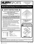
SAFETY INSTRUCTIONS
FAILURE TO FOLLOW THESE SAFETY INSTRUCTIONS MAY
RESULT IN SERIOUS INJURY,
PROPERTY DAMAGE AND WILL VOID WARRANTY.
This unit is intended for display purposes only and
should not be used for play.
To ensure safety, do not attempt to assemble this system without
following the instructions carefully. Check entire box and inside all
packing material for parts. Before beginning assembly, read the
instructions and identify parts in this document. Proper and
complete assembly, use and supervision is essential for proper
operation and to reduce the risk of accident or injury. A high
probability of serious injury exists if this system is not installed,
maintained, and operated properly.
• During assembly, if using a ladder use extreme caution. Two
people are recommended for this operation.
• If technical assistance is required, contact Huffy Sports’ Sample
and Display Technician.
• Serious injury could occur if teeth/face come in contact with
backboard, net or rim.
• Display recommended for 3” (7.6 cm) or 3-1/2” (9 cm) Round or
4” (10 cm) Square poles only.
• All instructions and warnings MUST accompany any display item
that is sold.
REQUIRED TOOLS AND
MATERIALS:
Most injuries are caused by misuse and/or not following
instructions.
Use caution when installing this unit.
• Wrenches: (Two each) 7/16”, 1/2”, 9/16”, and
3/4” or Pliers
• 3/16” Allen Wrench
• Step Ladder, 8 ft. (2.4 m)
IMPORTANT!
To ensure prompt and correct handling of any problems, or to answer any questions, please contact the Sample
and Display Technician: at 1-800-558-5234.
Internet Address: http://www.huffysports.com
1
01/05
P/N 21165502
PARTS LIST - See Hardware Identifier
Item Qty. Part No. Description
1
2
3
4
5
6
7
8
9
10
11
12
13
1 20176001 P.O.P. Sign
12 200892 Plastic Push Clips
20 201763 Bolt, Carriage, 3/8-16 x 6.5 Long
20 203232 Washer, Flat 3/8
20 202460 Saddle Clamp
20 203063 Lock Nut, 3/8-16
5
901097 Extension Arm, 3.5” Diameter
5
900897 3.5” Pole Section
10 201611 Bolt, Hex Flange, 5/16-18 x 3 Long
20 203218 Washer, Flat, 5/16
10 203100 Nut, Hex Flange 5/16-18
5
207103 Pole Cap for 3.5” Pole Section
5 200NET Spider Net
HARDWARE IDENTIFIER
Item #4 (20)
Item #6 (20)
Item #9 (10)
Item #11 (10)
Item #10 (20)
P/N 21165502
01/05
2
1.
2
1
P.O.P.
Portable
Basketball System
FRONT
2.
3
Install pegboard panels onto
corresponding side support
railings. Attach P.O.P. sign (1) to
lower peg board with plastic push
clips (2) so that it faces aisle as
shown.
01/05
P/N 21165502
3.
Install enclosed pole mounting hardware and pole
for each assembly.
WARNING
TWO PEOPLE ARE
NECESSARY TO MOUNT THE
ELEVATOR ASSEMBLY TO
THE POLE. ONE PERSON
SHOULD NOT ATTEMPT TO
DO THIS ALONE.
3-1/2” Rnd. Pole X 30” Pole
3
Upper Support
Railing
8
5
4
3-1/2” Rnd. Pole
3-1/2” Rnd. Pole
6
TOP
VIEW
NOTE:
Enclosed Are Two Sets Of
Brackets + Hardware For
(Each) Pole Installation
P/N 21165502
01/05
BACK
4
Pole Locations
Refer To Combo For
Goal Assembly
Instructions
1.
Mount extension arm (7) and
rim to backboard using
appropriate instruction sheet.
NOTE: For spring loaded rim
assembly, refer to
instructions included with
rim hardware.
7
2.
3.
Assemble spider net (13) to all
rims.
Secure extension arm (7) to 3.5”
pole section (8). Install pole cap
(12). Measure rim to be
regulation 10’ from the floor.
12
9
7
10
10
11
8
P/N 21165502
01/05
5
01/05
P/N 21165502
INSTALLATION DIAGRAM
WARNING
TWO PERSON MINIMUM
REQUIRED FOR THIS
PROCEDURE. NOT
FOLLOWING
RECOMMENDATION MAY
RESULT IN BODILY INJURY.
Assemble display products per diagram below.
909180
44” Rectangle
w/Slam Jam Rim
Hardware Kit 201667
LIFETIME UNITS
BOX OUT
909642
44” Fan Backboard
w/StandardRim
Hardware Kit
201672
BACK
BEAST
TITANIUM
P/N 21165502
01/05
939183
46” Rectangle
w/Slam Jam Rim
Steel Framed Acrylic
Hardware Kit 201670
6