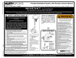
1
Portable Basketball System
Owners Manual
Customer Service Center
• N53 W24700 South Corporate Circle • Sussex, WI 53089 • U.S.A.
STROPSYFFUH
REQUIRED TOOLS AND MATERIALS:
Read and understand
operator's manual before
using this unit.
Failure to follow operating
instructions could result
in injury or damage to
property.
•
•
•
•
•
•
•
•
Two People
Wood Board (Scrap)
Tape Measure
Step Ladder 8 ft. (2.4 m)
Tape
Garden Hose or Sand 360 lb. (163 kg)
Hammer
Wrenches: (Two) 3/4”, (One) 1/2” (Two) 9/16”or
equivalent sockets, (One) 1/2” Deep well socket
with extension and socket wrench
• Support Table
• Phillips Head Screwdriver
Toll-Free Customer Service Number for U.S: 1-800-558-5234,
For Canada: 1-800-284-8339,
For Europe: 00 800 555 85234 (Sweden: 009 555 85234),
For Australia: 1-800-333 061
Internet Address: http://www.huffysports.com
1
© COPYRIGHT 2000 by HUFFY SPORTS
05/03
P/N 211689C
BEFORE YOU START!
To ensure optimal playability of backboard system, a close tolerance fit between the elevator
components and hardware is required. Test fit large bolts into large holes of elevator tubes,
backboard brackets and triangle plates. Carefully rock them in a circular motion to ream out
any excess paint from holes if necessary.
AVANT DE COMMENCER !
Pour garantir l'utilisation optimale du panneau, les composants du système élévateur et la visserie doivent être bien
ajustés (serrés). À titre d'essai, insérez les gros boulons dans les gros trous des tubes du système élévateur, des supports
du panneau et des plaques triangulaires. Basculez-les avec précaution en imprimant un mouvement circulaire pour
éliminer l'excédent de peinture, si nécessaire.
¡ANTES DE COMENZAR!
Para asegurar el óptimo rendimiento del sistema del respaldo en el juego, se requiere un ajuste de tolerancia estrecha
entre los componentes del elevador y el herraje. Pruebe el ajuste de los pernos grandes en los orificios grandes de los
tubos elevadores, soportes del respaldo y placas triangulares. Cuidadosamente muévalos en círculos para eliminar
cualquier exceso de pintura, si es necesario.
VORBEREITENDE MASSNAHMEN
Um sicherzustellen, dass das Korbwandsystem optimal für den Spielbetrieb geeignet ist, müssen die Komponenten der
Verlängerungsvorrichtung und die verschiedenen Befestigungsteile fest miteinander verschraubt werden. Große Schrauben
zur Probe in die großen Löcher der Verlängerungsrohre, Korbwandklammern und Dreiecksplatte stecken und diese
vorsichtig in einer Kreisbewegung hin- und herbewegen, um eventuelle Farbrückstände aus den Bohrungen zu entfernen.
P/N 211689C
05/03
2
WARNING
FAILURE TO FOLLOW THESE WARNINGS MAY RESULT
IN SERIOUS INJURY AND/OR PROPERTY DAMAGE.
Owner must ensure that all players know and follow
these rules for safe operation of the system.
• DO NOT HANG on the rim or any part of the system
including backboard, support braces or net.
• During play, especially when performing dunk type
activities, keep player's face away from the backboard, rim
and net. Serious injury could occur if teeth/face come in
contact with backboard, rim or net.
• Do not slide, climb, shake or play on base and/or pole.
• After assembly is complete, fill system completely with
water or sand and stake to the ground. Never leave system
in an upright position without filling base with weight, as
system may tip over causing injuries.
• When adjusting height or moving system, keep hands and
fingers away from moving parts.
• Do not allow children to move or adjust system.
• During play, do not wear jewelry (rings, watches, necklaces,
etc.). Objects may entangle in net.
• Surface beneath the base must be smooth and free of
gravel or other sharp objects. Punctures cause leakage and
could cause system to tip over.
• Keep organic material away from pole base. Grass, litter,
etc. could cause corrosion and/or deterioration.
• Check pole system for signs of corrosion (rust, pitting,
chipping) and repaint with exterior enamel paint. If rust has
penetrated through the steel anywhere, replace pole
immediately.
• Check system before each use for proper ballast, loose
hardware, excessive wear and signs corrosion and repair
before use.
• Check system before each use for instability.
• Do not use system during windy and/or severe weather
conditions; system may tip over. Place system in the
storage position and/or in an area protected from the wind
and free from personal property and/or overhead wires.
• Never play on damaged equipment.
• See instruction manual for proper installation and
maintenance.
• When moving system, use caution to keep mechanism from
shifting.
• Keep pole top covered with cap at all times.
• Do not allow water in tank to freeze. During sub-freezing
weather add non-toxic antifreeze, sand or empty tank
completely and store. (Do not use salt.)
• While moving system, Do not allow anyone to stand or sit
on base or have added ballasting on base.
• Do not leave system unsupervised or play on system when
wheels are engaged for moving.
• Use Caution when moving system across uneven surfaces.
System may tip over.
• Use extreme caution if placing system on sloped surface.
System may tip over more easily.
In the U.S.:1-800-558-5234 and Canada: 1-800-284-8339
201246
3
2/99
05/03
P/N 211689C
SAFETY INSTRUCTIONS
FAILURE TO FOLLOW THESE SAFETY INSTRUCTIONS MAY RESULT IN SERIOUS INJURY OR
PROPERTY DAMAGE AND WILL VOID WARRANTY.
Owner must ensure that all players know and follow these rules for safe operation of the system.
To ensure safety, do not attempt to assemble this system without following the instructions carefully. Proper
and complete assembly, use, and supervision are essential for proper operation and to reduce the risk of
accident or injury. A high probability of serious injury exists if this system is not installed, maintained, and
operated properly.
• If using a ladder during assembly, use extreme caution.
• Check base regularly for leakage. Slow leaks could cause the system to tip over
unexpectedly
• Seat the pole sections properly (if applicable). Failure to do so could allow the pole
sections to seperate during play and/or during transport of the system.
• Climate, corrosion or misuse could result in system failure.
• If technical assistance is required, contact Huffy Sports.
• Minimum operational height is 7'-6" (1.98m) to the bottom of backboard.
Most injuries are caused by misuse and/or not following instructions.
Use caution when using this unit.
NOTICE TO ASSEMBLERS
ALL Huffy Sports basketball systems, including those used for DISPLAYS, MUST be assembled
and ballasted with sand or water according to instructions. Failure to follow instructions could
result in SERIOUS INJURY. It is NOT acceptable to devise a makeshift weight system.
IMPORTANT!
Remove all contents from boxes.
Be sure to check inside pole sections;
hardware and additional parts are packed inside.
P/N 211689C
05/03
4
Get to know the basic parts of your basketball system.....
FRONT
BACK
BACKBOARD
RIM
ELEVATOR
ASSEMBLY
BOTTOM
POLE
TOP POLE
MIDDLE POLE
STRUTS
BASE
FRONT
COVER
WHEEL
CARRIAGE
ASSEMBLY
5
05/03
P/N 211689C
Item
Qty
1
2
3
4
5
6
7
8
9
10
11
12
13
14
15
16
17
18
19
20
21
22
23
24
25
26
27
28
29
30
31
32
33
34
35
36
37
38
39
40
41
42
43
44
45
46
47
48
49
50
51
52
53
54
55
56
57
58
59
60
61
62
63
64
65
66
67
68
1
1
1
2
2
2
4
1
1
1
7
1
1
2
1
1
1
2
1
5
1
17
1
1
1
4
1
1
1
1
1
4
2
1
4
1
9
2
4
8
1
8
2
1
1
2
2
6
2
1
4
12
1
2
1
1
1
2
1
1
1
1
1
1
2
2
2
1
P/N 211689C
05/03
Part No
900467
904811
903407
900223
206940
226403
206938
200117
203223
202662
203218
200188
202882
906410
200516
200123
206948
900122
200512
203232
206252
203100
203330
108053
206600
203103
108055
908052
201975
201973
201974
204804
900867
207103
908051
206910
206340
203053
202862
204847
201139
201682
203798
206151
203099
200874
206360
203063
900964
200118
265601
201278
204290
206219
202448
201568
202052
240027
900426
203092
201978
240019
108056
206956
226401
201651
202274
202273
Description
Top Pole Section
Middle Pole Section (with Label)
Bottom Pole Section
Wheel Bracket
Axle
Wheel 6”
Pushnut
Base
Carriage Bolt, 5/16-18 x 1
Hex Bolt, 5/16-18 x 4.5
Washer 5/16
Rod 3/8 x 5.25
EyeBolt 3/8 -16 x 3.75
Tank Strut
Bolt Cover
Upper Pivot Bracket
Lower Pivot Bracket
Hinge Tubes
WARRANTY CARD:
Hex Bolt 3/8 -16 x 3.5
Please remember to complete your product
Flat Washer 3/8 -3/4
registration form either on-line at:
Hex Bolt, 3/8 -16 x 1
www.huffysports.com/warrantycard or mail-in
Flange Nut 5/16 -18
the enclosed postcard.
Hex Bolt, 3/8 -16 x 4.5
Flipper
Elevator Shroud
Carriage Bolt, 5/16-18 x 2
Height Adjustment Shroud
Elevator Adjustment Tube
Trigger
Handle Right
Handle Left
Screw, Handle, #10 X 1"
Jack Plates
Pole Cap
Elevator Tube
Pole Bracket
Nut, Nylock, 1/2 -13
Pole Bracket Bolt 5/16-18 x 4
Spacer 1.19 long
Bolt 1/2 -13 x 9.5
Bolt 1/2 -13 x 4.5
Spacer 1.88 long
Bolt 5/16-18 x 1.5
Washer Flat
Nut, Nylock, 5/16-18
Spacer
Bolt 3/8 -16 x 2.625
Nut 3/8 -16 Nylock
Board Brackets
Front Cover
Front CoverCarriage Bolts
Net Clips
Net
Base Plug
Tie Down Stake
Anchor Strap
Label Height Adjust
Nut, Nylock 1/4-20
Gas Strut
Bolt 1/4-20 x 1.75
Height Label
Bolt 1/4-20 x .75
Plastic Lever
Plastic Disc
Wheel 4”
Spacer, Plastic, 1/4" Long
Spacer, Metal, 3-1/2" Long
Spacer, Metal, 5-7/8" Long
6
HARDWARE IDENTIFIER
Item #9 (1)
Item #7 (2)
Item #10 (1)
Item #15 (1)
Item #11 (7)
Item #13 (1)
Item #20 (5)
Item #19 (1)
Item #21 (1)
Item #23 (1)
Item #22 (16)
Item #26 (4)
Item #37 (9)
Item #32 (4)
Item #38 (2)
Item #39 (4)
7
05/03
P/N 211689C
HEIGHT ADJUSTMENT
TO ADJUST BACKBOARD:
1. Grasp handle and squeeze trigger.
2. Raise or lower to desired height.
Item #41 (1)
Item #44 (1)
3. Release trigger.
Item #40 (8)
MOVING SYSTEM
Item #48 (6)
1. Adjust basketball backboard
height to lowest position.
1
2. Rotate handle forward until
wheels engage ground.
3. Move basketball system to
desired location.
3
4. Rotate handle back to original
position.
2
5. Reattach ground restraint and
check system for stability.
4
Item #45 (1)
202052
02/03
Item #57 (1)
Item #47 (2)
Item #66 (2)
Item #51 (4)
Item #42 (8)
Item #60 (1)
Item #46 (2)
Item #43 (2)
Item #58 (2)
P/N 211689C
05/03
8
Item #62 (1)
SECTION A: ASSEMBLE THE POLES
1. Correctly identify each pole section. Mark pole sections with tape as shown.
1
3
2
5"
(13 cm)
TAPE
5"
(13 cm)
TAPE
2. Bounce middle pole section (2) into top pole section (1) together using a wood scrap
as shown until they no longer move toward taped reference mark.
NOTE: Pole sections should have a 3-1/2" (9 cm) minimum overlap.
2
IMPORTANT!:
1
Position middle pole so
that the warning label
is on the same side as
the 1/2" (cm) diameter
holes of the top pole.
Wood Scrap
9
05/03
P/N 211689C
3.
IMPORTANT! Holes in top (1) and bottom pole (3) sections MUST align to
correctly position elevator system toward playing surface.
While maintaining alignment, bounce assembly and lower section (3) together
as shown until they no longer move toward taped reference mark.
NOTE: Pole sections should have a 3-1/2" (9 cm) minimum overlap.
1/2" (1.27 cm) DIAMETER
HOLES OF TOP POLE
1
2
TAPE REFERENCE
MARK
3
WOOD SCRAP
(NOT SUPPLIED)
P/N 211689C
05/03
10
SECTION B: ASSEMBLE THE BASE
This is what your system will look like when
you’ve finished this section:
HARDWARE USED IN THIS SECTION
(not actual size)
TOOLS REQUIRED FOR THIS SECTION
1/2” & 9/16”
Item #9 (1)
AND
Item #7 (2)
Item #10 (1)
Item #15 (1)
Item #11 (6)
Item #13 (1)
9/16” & 1/2” AND EXTENSION
Item #20 (5)
Item #19 (1)
HAMMER OR MALLET
Item #21 (1)
Item #23 (1)
Item #22 (16)
Item #26 (4)
11
05/03
P/N 211689C
1.
Insert axle (5) through wheel bracket (4). Secure wheels (65) to
axle using pushnuts (7). Carefully tap pushnuts onto axle with
hammer or mallet
65
7
IMPORTANT!:
4
65
5
7
SIDE OF WHEEL WITH
LONGER PLASTIC AXLE
NEEDS TO FACE THE
WHEEL BRACKET.
2.
Install wheel assembly to base (8) using bolt (9), and nut (22) as
shown.
9
8
9
22
P/N 211689C
05/03
12
3. Install rod (12) through holes in bottom pole section (3) and eyebolt (13).
Insert pole assembly into tank (8) and through center hole on wheel assembly as
shown. Secure pole assembly with anchor strap (56), washer (11), and lock nut
WARNING:
TWO PEOPLE
REQUIRED FOR
THIS PROCEDURE.
FAILURE TO
FOLLOW THIS
WARNING COULD
RESULT IN SERIOUS
INJURY.
12
1
IMPORTANT!:
Smaller holes (11/32"/ .87 cm)
of top pole should face
toward the back of the system
and the warning label should
be facing toward the front.
2
3
13
12
8
13
56
11
48
13
05/03
P/N 211689C
4.
Secure tank struts (14) to pole as shown.
Place cap (15) over exposed end of bolt as shown.
WARNING:
TWO PEOPLE
REQUIRED FOR
THIS PROCEDURE.
FAILURE TO
FOLLOW THIS
WARNING COULD
RESULT IN SERIOUS
INJURY.
3
11
10
45
11
15
14
Rotate non-secured ends of tank struts (14) outward to mounting
holes in tank as shown.
14
P/N 211689C
05/03
14
14
Secure ends of tank struts (14) to tank as shown. Repeat for opposite
side.
5.
43
WARNING:
14
TWO PEOPLE
REQUIRED FOR
THIS PROCEDURE.
FAILURE TO
FOLLOW THIS
WARNING COULD
RESULT IN SERIOUS
INJURY.
11
11
22
6.
Install upper pivot bracket (16) to front of base using bolt (19), washer
(20) and nut (48) as shown.
48
20
16
19
15
05/03
P/N 211689C
7.
Insert bolt (21) through lower pivot bracket (17) as shown; bolt (21)
will be secured during step 10. Carefully place base assembly on its
side. Install lower pivot bracket (17) with bolt (23), washers (20), and
lock nut (48) as shown.
21
16
20
20
23
8.
48
17
Secure both hinge tubes (18) to second wheel bracket (4) with
carriage bolts (26) and flange nuts (22).
26
18
4
22
P/N 211689C
05/03
16
9.
Install wheels (6) onto axle (5) and wheel bracket (4) with push caps
(7) as shown.
6
4
7
5
6
7
10.
Position base as shown. Secure wheel bracket assembly with disc
(64), washer (20) and nut (48) as shown.
WARNING:
21
TWO PEOPLE
REQUIRED FOR THESE
PROCEDURES.
FAILURE TO FOLLOW
THIS WARNING COULD
RESULT IN SERIOUS
INJURY.
64
20
48
Carefully reposition entire assembly as shown.
17
05/03
P/N 211689C
SECTION C: ASSEMBLE THE ELEVATOR SYSTEM & BACKBOARD
This is what your system will look like when
you’ve finished this section:
HARDWARE USED IN THIS SECTION
(not actual size)
TOOLS REQUIRED FOR THIS SECTION
(2) 1/2”, (2) 3/4”
AND (2) 9/16”
Item #41 (1)
Item #22 (16)
Item #40 (8)
Item #44 (1)
Item #32 (4)
OR
Item #37 (9)
Item #38 (2)
Item #39 (4)
Item #15 (1)
Item #47 (2)
Item #42 (8)
Item #66 (2)
Item #48 (6)
Item #45 (1)
1/2” 9/16”
Item #51 (4)
Item #60 (1)
Item #43 (1)
3/4”
Item #58 (4)
Item #46 (2)
Item #62 (1)
P/N 211689C
05/03
18
1.
Slide shroud (25) back to expose bracket and assemble gas strut
components as shown. Do not over-tighten.
25
IMPORTANT!:
24
TO AVOID RAPID
EXTENSION OF
STRUT ROD - DO
NOT DEPRESS
BUTTON ON GAS
STRUT ASSEMBLY.
59
58
60
2. Carefully place end of cable into slot on bracket (24) as shown. Install strut shroud
(25) over strut assembly as shown.
IMPORTANT!:
Slot
TO AVOID RAPID
EXTENSION OF
STRUT ROD - DO
NOT DEPRESS
BUTTON ON GAS
STRUT ASSEMBLY.
25
24
19
05/03
P/N 211689C
63
3. Attach plastic lever (63) to
height adjustment shroud
(27) with bolt (62) and nut
(58) as shown.
58
27
62
5. Slide shroud assembly
Attach height
label (61) to the
front of the elevator
adjustment tube 11”
down from top of the
elevator adjustment tube
(28) as shown.
4.
onto elevator
adjustment tube (28)
as shown.
61
11”
'
10
'
9.5
05/03
20
'
P/N 211689C
9'
'
7.5
28
8'
28
8.5
61
Remove nuts from free end of cable. Insert cable into height adjustment tube as
shown (FIG. A). Pull cable through end of tube (FIG. B).
6.
FIG. B
FIG. A
28
7. Install pole bracket (36) to top pole as shown (FIG.A).
Reference finished assembly (FIG.B.)
22
22
67 & 38
67
36
36
FIG.A
38
FIG.B
21
05/03
P/N 211689C
8.
Identify elevator tubes.
Install triangle plates (33) and elevator tubes (35) to top pole section (1) as shown.
Install pole cap (34) at this time.
Toward
Pole
Toward
Board
35
Upper & Lower Elevator tube
IMPORTANT!:
Test-fit bolts into
holes; carefully rock
them in a circular
motion to ream out
paint from holes if
necessary.
37
35
35
37
39
33
34
1
33
35
35
41
40
40
P/N 211689C
05/03
22
9. Attach elevator
adjustment tube
(28) to elevator
tubes (35) with bolts
(40) spacers (42)
and nuts (37) as
shown.
37
35
42
28
42
35
40
40
10. Attach plastic lever
(63) to elevator
tubes (35) with bolt
(40) and nut (37) as
shown.
37
40
23
05/03
P/N 211689C
IMPORTANT!:
11. Insert spacer into strut assembly as shown
TO AVOID RAPID
EXTENSION OF
STRUT ROD - DO
NOT DEPRESS
BUTTON ON GAS
STRUT ASSEMBLY.
68
Attach front of gas strut assembly to elevator tubes (35) by rotating
elevator tubes (35) and inserting bolt (40) and nut (37) as shown.
35
37
40
35
35
P/N 211689C
05/03
24
12. Attach free end of gas
strut assembly to pole
bracket (36) with bolt (43)
spacers (66) and nut (45)
as shown.
36
66
NOTE: Gas strut (59) is
attached to front side of
pole.
66
59
IMPORTANT!:
43
45
TO AVOID RAPID
EXTENSION OF
STRUT ROD - DO
NOT DEPRESS
BUTTON ON GAS
STRUT ASSEMBLY.
13. Assemble brackets (49) to backboard using bolts (47) spacers (46) and nuts (48) as
shown. The spacers may fit very tightly between the brackets and may need to be
tapped into place with a hammer.
46
48
46
48
47
49
47
25
05/03
P/N 211689C
14. Assemble lower elevator tubes (35) and rim to brackets (49) using bolt (40),
spacers (42), and nut (37) as shown.
49
42
37
42
40
35
35
IMPORTANT!:
Refer To
Instructions
Included With Rim
Hardware For Rim
Assembly.
Use the 5/16-18 x 1"
hex-flange bolts for
installing rim to the
acrylic backboard.
P/N 211689C
05/03
26
15. Assemble upper elevator tubes (35) to brackets using bolt (40), spacers (42),
and nut (37) as shown.
37
42
49
42
40
35
35
27
05/03
P/N 211689C
SECTION D: INSTALL FRONT COVER & HANDLE
1. Attach front cover (50) to hinge tubes (18) using
carriage bolt (61) and flange nuts (15) as shown.
CAUTION!
DO NOT LEAVE ASSEMBLY
UNATTENDED WHEN EMPTY, IT
MAY TIP OVER.
15
50
61
P/N 211689C
05/03
28
18
2.
Re-install nuts and washer as shown. It is very
important to leave 1/8” of exposed thread on cable
as shown.
44
28
1/8”
3.
Install trigger (29) onto cable as shown.
29
28
29
28
29
05/03
P/N 211689C
4. Install handle (30) to height adjustment assembly with
screws (32) as shown. Be sure washer is seated in
slot on handle as shown (FIG. A).
31
29
30
FIG. A
P/N 211689C
05/03
30
32
SECTION E: INSTALL NET CLIPS AND NET
1. Install net clips.
WARNING: Use of this product without proper
installation of net clips, or when all net clips are not
present could result in bodily harm. Be sure to follow
directions carefully.
CLIP “ARM”
52
CLIP “BODY”
52
A
Insert one “arm” of clip (52) into ram as shown. Twist
“body” of clip slightly so that second “arm” slides over
the top of the first “arm” as shown.
Push in direction indicated by arrows.
Push second “arm” back and into ram as shown.
B
Twist “body” of clip slightly again to spread “arms” of clip.
Clip “arms” must be flat and touching edge-to-edge as
shown, without overlapping.
C
31
05/03
P/N 211689C
NET INSTALLATION
2.
SIDE VIEW
52
NETCLIP
53
NET
Insert net into bottom of clip as shown.
SIDE VIEW
Twist net until it snaps into position.
Net must be centered through clip.
NETCLIP
NET
P/N 211689C
05/03
32
SECTION F: SECURING THE SYSTEM
1. Roll assembly to desired playing area. Secure
assembly to ground using strap (56) and tie down stake
(55). Fill base (8) with water (approx. 40 gallons) and
snap fill cap (54) in place.
CAUTION!
DO NOT LEAVE ASSEMBLY
UNATTENDED WHEN EMPTY, IT
MAY TIP OVER.
ADD TWO GALLONS (7.6 LITERS)
OF NON-TOXIC ANTIFREEZE IN
SUB-FREEZING CLIMATES.
54
8
55
56
33
05/03
P/N 211689C
SECTION G: APPLY HEIGHT AND MOVING LABEL
1.
Apply Height Adjustment and Moving Label (57) to front of pole, where it is clearly
visible. Remove protective film from acrylic backboard.
57
HEIGHT ADJUSTMENT
TO ADJUST BACKBOARD:
1. Grasp handle and squeeze trigger.
2. Raise or lower to desired height.
3. Release trigger.
MOVING SYSTEM
1
1. Adjust basketball backboard
height to lowest position.
2. Rotate handle forward until
wheels engage ground.
3. Move basketball system to
desired location.
3
2
4
4. Rotate handle back to original
position.
5. Reattach ground restraint and
check system for stability.
202052
P/N 211689C
05/03
34
02/03
SECTION H: TROUBLESHOOTING GUIDE
1. If the elevator is still difficult to operate, verify that the valve located on the strut is
fully depressed when the trigger is activated.
WARNING!
TWO PEOPLE
REQUIRED FOR THIS
PROCEDURE. FAILURE
TO FOLLOW THIS
WARNING COULD
RESULT IN SERIOUS
INJURY AND/OR
PROPERTY DAMAGE.
59
IMPORTANT!:
Pin must be fully
depressed so that the
backboard assembly
can move freely
2. To allow easy movement, or if system does not lock when the trigger is released,
two adjustments can be made.
A.
B.
Slide shroud back to expose bracket and cable.
Remove right handle to allow access to trigger and cable
mechanism.
• If the system does not move freely, loosen nuts and
adjust cable toward gas strut.
• If the system does not lock when the trigger is
released, adjust cable away from gas strut.
• If system is not moving freely, loosen nuts and adjust cable
away from trigger.
• If the system does not lock when the trigger is released, adjust
cable toward trigger.
Tighten nuts and slide shroud back into position.
Reconnect right handle.
Lock
Unlock
Lock
35
Unlock
05/03
P/N 211689C