1
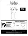
Display System
Owners Manual
Customer Service Center
• N53 W24700 South Corporate Circle • Sussex, WI 53089 • U.S.A.
Model
89226
WARNING!
REQUIRED TOOLS AND MATERIALS:
READ AND UNDERSTAND
OPERATOR'S MANUAL
BEFORE USING THIS UNIT.
• 2 People
FAILURE TO FOLLOW
OPERATING INSTRUCTIONS
COULD RESULT IN INJURY
OR DAMAGE TO PROPERTY.
• 2 Stepladders
• (2 each) Wrenches and/or
Socket Wrenches and
Sockets.
7/16"
1/2"
9/16"
AND/OR
• Phillips Screwdriver
7/16"
1/2"
9/16"
IMPORTANT!
To ensure prompt and correct handling of any problems, or to answer any questions, please contact the Sample and
Display Technician at 1-800-558-5234.
1
P/N 21155402
09/04
NOTICE TO ASSEMBLERS
ALL Huffy Sports Basketball Systems, including those used for DISPLAYS, MUST be assembled
and ballasted with sand or water according to the instructions. Failure to follow instructions
could result in SERIOUS INJURY. It is NOT acceptable to devise a makeshift weight system.
IMPORTANT!
Remove all contents from boxes.
Be sure to check inside pole sections;
hardware and additional parts are packed inside.
SAFETY INSTRUCTIONS
FAILURE TO FOLLOW THESE SAFETY INSTRUCTIONS MAY
RESULT IN SERIOUS INJURY,
PROPERTY DAMAGE AND WILL VOID WARRANTY.
This unit is intended for display purposes only and
should not be used for play.
To ensure safety, do not attempt to assemble this system without
following the instructions carefully. Check entire box and inside all
packing material for parts. Before beginning assembly, read the
instructions and identify parts in this document. Proper and
complete assembly, use and supervision is essential for proper
operation and to reduce the risk of accident or injury. A high
probability of serious injury exists if this system is not installed,
maintained, and operated properly.
• During assembly, if using a ladder use extreme caution. Two
people are recommended for this operation.
• If technical assistance is required, contact Huffy Sports’ Sample and
Display Technician.
• Serious injury could occur if teeth/face come in contact with
backboard, net or rim.
• Display recommended for 3” (7.6 cm) or 3-1/2” (9 cm) Round or 4”
(10 cm) Square poles only.
• All instructions and warnings MUST accompany any display item
that is sold.
Most injuries are caused by misuse and/or not following
instructions.
Use caution when installing this unit.
P/N 21155402
09/04
2
PARTS LIST (See Hardware Identifier)
Item Qty. Part No.
Description
Item Qty. Part No.
Description
1
2
3
4
5
6
7
8
9
10
11
12
13
14
15
16
17
18
Bracket, Reinforcement S/J
P/S Cover
Screw, #8 x 3/4", Flat Hd, Phillips
Spacer, Mounting
Net Clips
Plastic Knob
Bolt,Hex-Flange, 5/16-18 x 3"
NBA Sticker
Locknut, 3/8-16 Nylon Insert
Bolt, Carriage, 5/16-18 x 2.25"
Nut, Hex-Flange 5/16-18 Whiz Lock
Bolt, Carriage, 5/16-18 x 3.5"
Bolt, U, Round, 3/8-16 x 3.5"
Washer
Washer, Flat, S/J
Spring
Nut, 3/8-16 Special S/J
T-bolt, 3/8-16 x 5"
19
20
21
22
23
24
25
26
27
28
29
30
31
32
33
34
Bolt, Hex 5/16-18 x 1.5"
Net
Pole Cap, 3"
Pole Cap, 3.5"
Bracket, S/J
Pole, 3"
Rim
Bracket, Pole Mount, No Tools
Wedge
Board, 48", Fan, Viper
Board, 44", Fan, Evolution, NT
Board, 44", Fan, Zone Attack
Extension Arm
Board, 48", SFA, Titanium II
Pole, 3.5"
Pole Sleeve
3
1
2
2
48
3
12
1
12
1
12
2
6
4
2
2
2
2
200318
200503
200520
200533
201219
201344
201611
202795
203063
203157
203100
203231
203294
203309
203470
203472
203795
203796
7
4
1
3
2
1
4
1
7
1
1
1
3
1
3
1
203798
204290
206219
207103
900033
900060
900253
206987
909256
909259
909602
912006
939235
990062
204516
HARDWARE IDENTIFIER (BOLTS & SCREWS)
Item #7 (1)
Item #10 (1)
Item #19 (7)
Item #3 (2)
Item #12 (2)
Item #18 (2)
HARDWARE IDENTIFIER (NUTS, WASHERS & SPRINGS)
Item #17 (2)
Item #9 (12)
Item #14 (4)
Item #15 (2)
Item #11 (12)
Item #16 (2)
3
P/N 21155402
09/04
Install display boards in the marked locations. Each mounting location consists of a mounting pole stub with
the following dimensions: Height = 8”, O.D. = 3 3/8”, I.D. = 3 1/8” (arrows indicate direction the board is
facing).
Display Stand - Top View
3-1/2"
3"
Corner “4”
80602
Corner “3”
61259
Corner “2”
73256
Corner “1”
9H235A
3-1/2"
3-1/2"
Display boards will be mounted as follows:
Corner Location 1: 9H235A
• 48” SFA Board
• Titanium II Logo
• Black Slam Jam Goal with Cover
• Use extension arm for assembly
Corner Location 2: 73256
• 48” Fan Recycled Board
• Viper Logo
• Black Slam Jam Goal
• Use extension arm for assembly
Corner Location 3: 61259
• 44” Fan Recycled Board
• Evolution Logo
• Black Standard Goal
• No Tools, E3 Elevator System
Corner Location 4: 80602
• 44” Fan Recycled Board
• Zone Attack Logo
• Black Standard Goal
• Use extension arm for assembly
P/N 21155402
09/04
4
1a.
At corner location 3
slide the pole sleeve
(34) inside the
mounting stub.
34
1b.
Slide the 3" diameter end of
the display pole (24) inside
the pole sleeve.
24
Secure the display pole by
sliding the display wedge
(27) into position as shown.
To lock the display pole in
place, tighten the hex-bolt
(19).
24
27
19
2a.
At corner location 1, 2 and 4 slide the
3-1/2" diameter end of the display pole
(33) inside the mounting stubs.
2b.
Secure the display pole by sliding the display wedge (27)
into position as shown. To lock the display pole in place,
tighten the hex-bolt (19).
33
19
27
19
27
5
P/N 21155402
09/04
Corner Location 1: STEEL FRAME ACRYLIC BACKBOARD ASSEMBLY
11
Display Stand - Top View
3-1/2"
31
3"
Corner “4”
80602
Corner “3”
61259
32
4
Corner “2”
73256
Corner “1”
9H235A
3-1/2"
3-1/2"
18
1.
Insert “T” bolt (18) through Slam Jam bracket (23) as shown.
Secure Slam Jam bracket (23), extension arm (31) and
mounting spacers (4) assemblies to backboard using bolt (7 )
and nut (11) as shown.
23
7
2.
Attach board assembly to pole.
32
WARNING!
TWO PEOPLE REQUIRED
FOR THIS PROCEDURE.
FAILURE TO FOLLOW
THIS WARNING COULD
RESULT IN SERIOUS
INJURY AND/OR
PROPERTY DAMAGE.
22
13
9
P/N 21155402
09/04
6
NOTE:
3.
Tighten nut (17) until
flush with end of "T" bolt
(18) as shown here.
• Fit rim (25) securely into bracket (23) as shown.
• Install reinforcement bracket (1) onto “T” bolt (18) as shown.
• Install spring (16) onto “T” bolt (18) as shown.
• Install special nut (17) and washer (15) onto “T” bolt (18).
25
17
18
NOTE:
Peel protective film
from surface of
acrylic backboard
prior
to use.
4.
Attach cover (2) to rim using
screws (3).
15
16
1
23
5.
Apply logo label (8) to rim cover (2).
3
25
2
2
8
7
P/N 21155402
09/04
Corner Location 2: 48” FAN MOLDED PLASTIC BOARD ASSEMBLY
11
Display Stand - Top View
3-1/2"
3"
Corner “4”
80602
31
Corner “3”
61259
28
Corner “2”
73256
Corner “1”
9H235A
3-1/2"
3-1/2"
1.
Insert “T” bolt (18) through Slam Jam bracket
(23) as shown.
Secure Slam Jam bracket (23) and extension
arm (31) to backboard using bolt (7) and nut
(11) as shown.
18
18
Tighten completely.
23
7
2.
Attach board assembly to pole.
28
WARNING!
TWO PEOPLE REQUIRED
FOR THIS PROCEDURE.
FAILURE TO FOLLOW
THIS WARNING COULD
RESULT IN SERIOUS
INJURY AND/OR
PROPERTY DAMAGE.
22
13
9
P/N 21155402
09/04
8
3.
• Fit rim (25) securely into bracket (23) as shown.
• Install reinforcement bracket (1) onto “T” bolt (18) as shown.
• Install spring (16) onto “T” bolt (18) as shown.
• Install special nut (17) and washer (15) onto “T” bolt (18).
25
17
18
NOTE:
Tighten nut (17) until
flush with end of "T" bolt
(18) as shown here.
15
16
23
1
9
P/N 21155402
09/04
Corner Location 3: 44" FAN MOLDED PLASTIC BOARD ASSEMBLY
1.
Pole bracket will need to be lightly pressed into
backboard ribbing. Be sure to press completely into
place. Attach rim (25) to backboard and pole bracket
(26) with knob (6), reinforcement bracket (1), and
carriage bolt (10) as shown. Tighten knob
completely.
Display Stand - Top View
3-1/2"
3"
Corner “4”
80602
Corner “3”
61259
WARNING!
KNOB MUST BE TIGHTENED
COMPLETELY AND CHECKED
FOR TIGHTNESS BEFORE
EACH USE.
29
6
Corner “2”
73256
Corner “1”
9H235A
1
3-1/2"
3-1/2"
25
NOTE:
10
BOARD STYLE
MAY VARY
26
PRESS BRACKET (26)
INTO PLACE HERE
2.
Attach board assembly to pole with carriage
bolts (12) and knobs (6) as shown. Install pole
cap (21) as shown.
21
6
24
P/N 21155402
09/04
10
12
Corner Location 4: 44" FAN MOLDED PLASTIC BOARD ASSEMBLY
11
Display Stand - Top View
3-1/2"
31
3"
Corner “4”
80602
Corner “3”
61259
30
Corner “2”
73256
Corner “1”
9H235A
3-1/2"
3-1/2"
1.
Attach rim (25) to backboard (30) and
extension arm (31) with bolts (7), washers (14)
and nuts (11).
14
25
Tighten completely.
7
2.
Attach board assembly to pole.
30
WARNING!
TWO PEOPLE REQUIRED
FOR THIS PROCEDURE.
FAILURE TO FOLLOW
THIS WARNING COULD
RESULT IN SERIOUS
INJURY AND/OR
PROPERTY DAMAGE.
22
13
9
11
P/N 21155402
09/04
11.
Install net clips.
CLIP “ARM”
WARNING!
USE OF THIS PRODUCT
WITHOUT PROPER
INSTALLATION OF SMART
CLIPS®, OR WHEN ALL SMART
CLIPS® ARE NOT PRESENT
COULD RESULT IN BODILY
HARM. BE SURE TO FOLLOW
DIRECTIONS CAREFULLY.
CLIP “BODY”
25
Insert one “arm” of clip into ram as shown. Twist “body” of clip
slightly so that second “arm” slides over the top of the first “arm” as
shown.
Push in direction indicated by arrows.
5
A
Push second “arm” back and into ram as shown.
B
Twist “body” of clip slightly again to spread “arms” of clip.
Clip “arms” must be flat and touching edge to edge as shown, not
overlapping.
C
P/N 21155402
09/04
12
12.
Install net.
25
SIDE VIEW
20
5
NETCLIP
NET
Insert net into bottom of clip as shown.
SIDE VIEW
Twist net until it snaps into position.
Net must be centered through clip.
NETCLIP
NET
13
P/N 21155402
09/04