1
HP Scalable File Share User Guide
G3.2-0
HP Part Number: SFSUGG32-E
Published: May 2010
Edition: 5
© Copyright 2010 Hewlett-Packard Development Company, L.P.
Confidential computer software. Valid license from HP required for possession, use or copying. Consistent with FAR 12.211 and 12.212, Commercial
Computer Software, Computer Software Documentation, and Technical Data for Commercial Items are licensed to the U.S. Government under
vendor's standard commercial license. The information contained herein is subject to change without notice. The only warranties for HP products
and services are set forth in the express warranty statements accompanying such products and services. Nothing herein should be construed as
constituting an additional warranty. HP shall not be liable for technical or editorial errors or omissions contained herein.
Intel, Intel Xeon, and Itanium are trademarks or registered trademarks of Intel Corporation or its subsidiaries in the U.S. and other countries.
InfiniBand is a registered trademark and service mark of the InfiniBand Trade Association.
Lustre and the Lustre Logo are trademarks of Sun Microsystems.
Myrinet and Myricom are registered trademarks of Myricom Inc.
Quadrics and QsNetII are trademarks or registered trademarks of Quadrics, Ltd.
UNIX is a registered trademark of The Open Group.
Voltaire, ISR 9024, Voltaire HCA 400, and VoltaireVision are all registered trademarks of Voltaire, Inc.
Red Hat is a registered trademark of Red Hat, Inc.
Fedora is a trademark of Red Hat, Inc.
SUSE is a registered trademark of SUSE AG, a Novell business.
AMD Opteron is a trademark of Advanced Micro Devices, Inc.
Sun and Solaris are trademarks or registered trademarks of Sun Microsystems, Inc. in the United States and other countries.
Table of Contents
About This Document.......................................................................................................11
Intended Audience................................................................................................................................11
New and Changed Information in This Edition...................................................................................11
Typographic Conventions.....................................................................................................................11
Related Information..............................................................................................................................12
Structure of This Document..................................................................................................................13
Documentation Updates.......................................................................................................................13
HP Encourages Your Comments..........................................................................................................13
1 What's In This Version.................................................................................................15
1.1 About This Product.........................................................................................................................15
1.2 Benefits and Features......................................................................................................................15
1.3 Supported Configurations ..............................................................................................................15
1.3.1 Hardware Configuration.........................................................................................................16
1.3.1.1 Server Memory Requirements........................................................................................18
1.3.1.2 Fibre Channel Switch Zoning..........................................................................................19
1.4 Server Security Policy......................................................................................................................19
1.5 Release Notes...................................................................................................................................20
1.5.1 New and Changed Information in This Edition.....................................................................20
1.5.2 Bug Fixes.................................................................................................................................20
1.5.3 Known Issues..........................................................................................................................20
2 Installing and Configuring MSA Arrays.....................................................................21
2.1 Installation.......................................................................................................................................21
2.2 Accessing the MSA CLI...................................................................................................................21
2.3 Using the CLI to Configure Multiple MSA Arrays.........................................................................21
2.3.1 Configuring New Volumes.....................................................................................................21
2.3.2 Creating New Volumes...........................................................................................................22
2.4 MSA2000 Monitoring......................................................................................................................24
2.4.1 email Notifications..................................................................................................................25
2.4.1.1 GUI Method....................................................................................................................25
2.4.1.2 CLI Method.....................................................................................................................25
2.4.1.3 Mail Server Configuration...............................................................................................25
2.4.2 SNMP Monitoring...................................................................................................................26
3 Installing and Configuring HP SFS Software on Server Nodes..............................27
3.1 Supported Firmware ......................................................................................................................28
3.2 Installation Requirements...............................................................................................................29
3.2.1 Kickstart Template Editing......................................................................................................29
3.3 Installation Phase 1..........................................................................................................................30
3.3.1 DVD/NFS Kickstart Procedure................................................................................................30
3.3.2 DVD/USB Drive Kickstart Procedure.....................................................................................31
3.3.3 Network Installation Procedure..............................................................................................32
3.4 Installation Phase 2..........................................................................................................................33
3.4.1 Patch Download and Installation Procedure..........................................................................33
3.4.2 Run the install2.sh Script.................................................................................................33
3.4.3 10 GigE Installation.................................................................................................................33
3.5 Configuration Instructions..............................................................................................................34
Table of Contents
3
3.5.1 Configuring Ethernet and InfiniBand or 10 GigE Interfaces..................................................34
3.5.2 Creating the /etc/hosts file................................................................................................35
3.5.3 Configuring pdsh...................................................................................................................35
3.5.4 Configuring ntp......................................................................................................................35
3.5.5 Configuring User Credentials.................................................................................................35
3.5.6 Verifying Digital Signatures (optional)...................................................................................36
3.5.6.1 Verifying the HP Public Key (optional)..........................................................................36
3.5.6.2 Verifying the Signed RPMs (optional)............................................................................36
3.6 Upgrade Installation........................................................................................................................37
3.6.1 Rolling Upgrades.....................................................................................................................37
3.6.2 Client Upgrades.......................................................................................................................39
4 Installing and Configuring HP SFS Software on Client Nodes...............................41
4.1 Installation Requirements...............................................................................................................41
4.1.1 Client Operating System and Interconnect Software Requirements......................................41
4.1.2 InfiniBand Clients....................................................................................................................41
4.1.3 10 GigE Clients........................................................................................................................41
4.2 Installation Instructions...................................................................................................................42
4.3 Custom Client Build Procedures.....................................................................................................43
4.3.1 CentOS 5.3/RHEL5U3 Custom Client Build Procedure..........................................................43
4.3.2 SLES10 SP2 Custom Client Build Procedure...........................................................................44
5 Using HP SFS Software................................................................................................45
5.1 Creating a Lustre File System..........................................................................................................45
5.1.1 Creating the Lustre Configuration CSV File...........................................................................45
5.1.1.1 Multiple File Systems......................................................................................................47
5.1.2 Creating and Testing the Lustre File System...........................................................................47
5.2 Configuring Heartbeat....................................................................................................................48
5.2.1 Preparing Heartbeat................................................................................................................48
5.2.2 Generating Heartbeat Configuration Files Automatically......................................................49
5.2.3 Configuration Files..................................................................................................................49
5.2.3.1 Generating the cib.xml File..........................................................................................50
5.2.3.2 Editing cib.xml.............................................................................................................51
5.2.4 Copying Files...........................................................................................................................51
5.2.5 Things to Double-Check..........................................................................................................52
5.2.6 Things to Note.........................................................................................................................52
5.2.7 Preventing Collisions Among Multiple HP SFS Servers........................................................52
5.3 Starting the File System...................................................................................................................53
5.4 Stopping the File System.................................................................................................................53
5.5 Monitoring Failover Pairs................................................................................................................54
5.6 Moving and Starting Lustre Servers Using Heartbeat....................................................................54
5.7 Testing Your Configuration.............................................................................................................55
5.7.1 Examining and Troubleshooting.............................................................................................55
5.7.1.1 On the Server...................................................................................................................55
5.7.1.2 The writeconf Procedure.................................................................................................56
5.7.1.3 On the Client...................................................................................................................58
5.8 Lustre Performance Monitoring......................................................................................................59
6 Licensing........................................................................................................................61
6.1 Obtaining a New License................................................................................................................61
6.2 Installing a New License.................................................................................................................61
6.3 Checking for a Valid License...........................................................................................................61
4
Table of Contents
7 Known Issues and Workarounds................................................................................63
7.1 Server Reboot...................................................................................................................................63
7.2 Errors from install2....................................................................................................................63
7.3 Application File Locking.................................................................................................................63
7.4 MDS Is Unresponsive......................................................................................................................63
7.5 Changing group_upcall Value to Disable Group Validation.....................................................63
7.6 Configuring the mlocate Package on Client Nodes......................................................................64
7.7 System Behavior After LBUG..........................................................................................................64
7.8 SELinux Support.............................................................................................................................64
7.9 Misconfigured Lustre target config logs due to incorrect CSV file used during
lustre_config..................................................................................................................................65
7.10 MSA2000fc G1 incorrect MSA cabling between MSA2212fc controllers and SAN switches with
zoned SAN switch. ...............................................................................................................................66
7.11 Standby server does not take over neighboring resources............................................................66
A HP SFS G3 Performance.............................................................................................67
A.1 Benchmark Platform.......................................................................................................................67
A.2 Single Client Performance..............................................................................................................68
A.3 Throughput Scaling........................................................................................................................70
A.4 One Shared File..............................................................................................................................72
A.5 Stragglers and Stonewalling...........................................................................................................72
A.6 Random Reads................................................................................................................................73
A.7 DDR InfiniBand Performance Using MSA2312 with Three Attached JBODs...............................74
A.7.1 Benchmark Platform...............................................................................................................74
A.7.2 Single Stream Throughput.....................................................................................................75
A.7.3 Throughput Scaling................................................................................................................76
A.8 10 GigE Performance......................................................................................................................76
A.8.1 Benchmark Platform...............................................................................................................77
A.8.2 Single Stream Throughput.....................................................................................................78
A.8.3 Throughput Scaling................................................................................................................79
Index.................................................................................................................................81
Table of Contents
5
6
List of Figures
1-1
1-2
7-1
A-1
A-2
A-3
A-4
A-5
A-6
A-7
A-8
A-9
A-10
A-11
A-12
A-13
A-14
A-15
A-16
A-17
Platform Overview........................................................................................................................17
Server Pairs....................................................................................................................................18
MSA2000fc G1 cabling...................................................................................................................66
Benchmark Platform......................................................................................................................67
Storage Configuration...................................................................................................................68
Single Stream Throughput............................................................................................................69
Single Client, Multi-Stream Write Throughput.............................................................................69
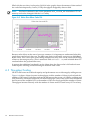
Writes Slow When Cache Fills.......................................................................................................70
Multi-Client Throughput Scaling..................................................................................................71
Multi-Client Throughput and File Stripe Count...........................................................................71
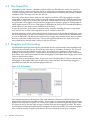
Stonewalling..................................................................................................................................72
Random Read Rate........................................................................................................................73
Deep Shelf DDR IB Test Configuration.........................................................................................74
Stripe Count Versus Total Throughput (MB/s).............................................................................75
Client Count Versus Total Throughput (MB/s).............................................................................76
Stripe Count Versus Total Throughput (MB/s) – Single File.........................................................76
10 GigE Connection.......................................................................................................................77
Stripe Count Versus Total Throughput (MB/s).............................................................................78
Client Count Versus Total Throughput (MB/s).............................................................................79
Stripe Count Versus Total Throughput (MB/s).............................................................................79
7
8
List of Tables
1-1
3-1
Supported Configurations ............................................................................................................15
Minimum Firmware Versions.......................................................................................................28
9
10
About This Document
This document provides installation and configuration information for HP Scalable File Share
(SFS) G3.2-0. Overviews of installing and configuring the Lustre® File System and MSA Storage
Arrays are also included in this document.
Pointers to existing documents are provided where possible. Refer to those documents for related
information.
Intended Audience
This document is intended for anyone who installs and uses HP SFS. The information in this
guide assumes that you have experience with the following:
• The Linux operating system and its user commands and tools
• The Lustre File System
• Smart Array storage administration
• HP rack-mounted servers and associated rack hardware
• Basic networking concepts, network switch technology, and network cables
New and Changed Information in This Edition
For information about new and changed features in this release, see “Release Notes” (page 20).
Typographic Conventions
This document uses the following typographical conventions:
%, $, or #
audit(5)
Command
Computer output
Ctrl+x
ENVIRONMENT VARIABLE
[ERROR NAME]
Key
Term
User input
Variable
[]
{}
...
\
|
A percent sign represents the C shell system prompt. A dollar
sign represents the system prompt for the Bourne, Korn, and
POSIX shells. A number sign represents the superuser prompt.
A manpage. The manpage name is audit, and it is located in
Section 5.
A command name or qualified command phrase.
Text displayed by the computer.
A key sequence. A sequence such as Ctrl+x indicates that you
must hold down the key labeled Ctrl while you press another
key or mouse button.
The name of an environment variable, for example, PATH.
The name of an error, usually returned in the errno variable.
The name of a keyboard key. Return and Enter both refer to the
same key.
The defined use of an important word or phrase.
Commands and other text that you type.
The name of a placeholder in a command, function, or other
syntax display that you replace with an actual value.
The contents are optional in syntax. If the contents are a list
separated by |, you must choose one of the items.
The contents are required in syntax. If the contents are a list
separated by |, you must choose one of the items.
The preceding element can be repeated an arbitrary number of
times.
Indicates the continuation of a code example.
Separates items in a list of choices.
Intended Audience
11
WARNING
CAUTION
IMPORTANT
NOTE
A warning calls attention to important information that if not
understood or followed will result in personal injury or
nonrecoverable system problems.
A caution calls attention to important information that if not
understood or followed will result in data loss, data corruption,
or damage to hardware or software.
This alert provides essential information to explain a concept or
to complete a task.
A note contains additional information to emphasize or
supplement important points of the main text.
Related Information
Pointers to existing documents are provided where possible. Refer to those documents for related
information.
For Sun Lustre documentation, see:
http://manual.lustre.org
The Lustre 1.8 Operations Manual is installed on the system in
/opt/hp/sfs/doc/LustreManual_v1_8.pdf. Or refer to the Lustre website:
http://manual.lustre.org/images/7/7f/820-3681_v1_1.pdf
For HP XC Software documentation, see:
http://docs.hp.com/en/linuxhpc.html
For MSA2000 products, see:
http://www.hp.com/go/msa2000
For HP servers, see:
http://www.hp.com/go/servers
For InfiniBand information, see:
http://www.hp.com/products1/serverconnectivity/adapters/infiniband/specifications.html
For Fibre Channel networking, see:
http://www.hp.com/go/san
For HP support, see:
http://www.hp.com/support
For product documentation, see:
http://www.hp.com/support/manuals
For collectl documentation, see:
http://collectl.sourceforge.net/Documentation.html
For Heartbeat information, see:
http://www.linux-ha.org/Heartbeat
For HP StorageWorks Smart Array documentation, see:
HP StorageWorks Smart Array Manuals
For SFS Gen 3 Cabling Tables, see: http://docs.hp.com/en/storage.html and click the Scalable File
Share (SFS) link.
For SFS V2.3 Release Notes, see:
HP StorageWorks Scalable File Share Release Notes Version 2.3
12
For documentation of previous versions of HP SFS, see:
• HP StorageWorks Scalable File Share Client Installation and User Guide Version 2.2 at:
http://docs.hp.com/en/8957/HP_StorageWorks_SFS_Client_V2_2-0.pdf
Structure of This Document
This document is organized as follows:
Chapter 1
Provides information about what is included in this product.
Chapter 2
Provides information about installing and configuring MSA arrays.
Chapter 3
Provides information about installing and configuring the HP SFS Software on the
server nodes.
Chapter 4
Provides information about installing and configuring the HP SFS Software on the
client nodes.
Chapter 5
Provides information about using the HP SFS Software.
Chapter 6
Provides information about licensing.
Chapter 7
Provides information about known issues and workarounds.
Appendix A
Provides performance data.
Documentation Updates
Documentation updates (if applicable) are provided on docs.hp.com. Use the release date of a
document to determine that you have the latest version.
HP Encourages Your Comments
HP encourages your comments concerning this document. We are committed to providing
documentation that meets your needs. Send any errors found, suggestions for improvement, or
compliments to:
http://docs.hp.com/en/feedback.html
Include the document title, manufacturing part number, and any comment, error found, or
suggestion for improvement you have concerning this document.
Structure of This Document
13
14
1 What's In This Version
1.1 About This Product
HP SFS G3.2-0 uses the Lustre File System on MSA hardware to provide a storage system for
standalone servers or compute clusters.
Starting with this release, HP SFS servers can be upgraded. If you are upgrading from one version
of HP SFS G3 to a more recent version, see the instructions in “Upgrade Installation” (page 37).
IMPORTANT: If you are upgrading from HP SFS version 2.3 or older, you must contact your
HP SFS 2.3 support representative to obtain the extra documentation and tools necessary for
completing that upgrade. The upgrade from HP SFS version 2.x to HP SFS G3 cannot be done
successfully with just the HP SFS G3 CD and the user's guide.
HP SFS 2.3 to HP SFS G3 upgrade documentation and tools change regularly and independently
of the HP SFS G3 releases. Verify that you have the latest available versions.
If you are upgrading from one version of HP SFS G3, on a system that was previously upgraded
from HP SFS version 2.3 or older, you must get the latest upgrade documentation and tools from
HP SFS 2.3 support.
1.2 Benefits and Features
HP SFS G3.2-0 consists of a software set required to provide high performance and highly available
Lustre File System service over InfiniBand or 10 Gigabit Ethernet (GigE) for HP MSA storage
hardware. The software stack includes:
•
•
•
•
•
•
•
Lustre Software 1.8.0.1
Open Fabrics Enterprise Distribution (OFED) 1.4.1
Mellanox 10 GigE driver
Heartbeat V2.1.3
collectl (for system performance monitoring)
pdsh for running file system server-wide commands
Other scripts, tests, and utilities
1.3 Supported Configurations
HP SFS G3.2-0 supports the following configurations:
Table 1-1 Supported Configurations
Component
Supported
Client Operating Systems
CentOS 5.2 and 5.3, RHEL5U2 and U3, SLES10 SP2, XCV4
Client Platform
Opteron, Xeon
Lustre Software
V1.8.0.1
Server Operating System
CentOS 5.31
Server Nodes
ProLiant DL380 G5 and G6
Storage Array
MSA2212fc and MSA2312fc
Interconnect
OFED 1.4.1 InfiniBand or 10 GigE
Storage Array Drives
SAS, SATA
ProLiant Support Pack (PSP)
8.20
1.1 About This Product
15
1
CentOS 5.3 is available for download from the HP Software Depot at:
http://www.hp.com/go/softwaredepot
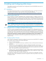
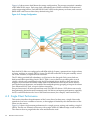
1.3.1 Hardware Configuration
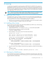
A typical HP SFS system configuration consists of the base rack only that contains:
• ProLiant DL380 MetaData Servers (MDS), administration servers, and Object Storage Servers
(OSS)
• HP MSA2212fc or MSA2312fc enclosures
• Management network ProCurve Switch
• SAN switches
• InfiniBand or 10 GigE switches
• Keyboard, video, and mouse (KVM) switch
• TFT console display
All DL380 file system servers must have their eth0 Ethernet interfaces connected to the ProCurve
Switch making up an internal Ethernet network. The iLOs for the DL380 servers should also be
connected to the ProCurve Switch, to enable Heartbeat failover power control operations. HP
recommends at least two nodes with Ethernet interfaces be connected to an external network.
DL380 file system servers using HP SFS G3.2-0 must be configured with mirrored system disks
to protect against a server disk failure. Use the ROM-based HP ORCA Array Configuration utility
to configure mirrored system disks (RAID 1) for each server by pressing F8 during system boot.
More information is available at:
http://h18004.www1.hp.com/products/servers/proliantstorage/software-management/acumatrix/index.html
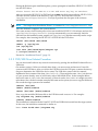
The MDS server, administration server, and each pair of OSS servers have associated HP MSA
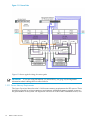
enclosures. Figure 1-1 provides a high-level platform diagram. For detailed diagrams of the MSA
controller and the drive enclosure connections, see the HP StorageWorks 2012fc Modular Smart
Array User Guide at:
http://bizsupport.austin.hp.com/bc/docs/support/SupportManual/c01394283/c01394283.pdf
16
What's In This Version
Figure 1-1 Platform Overview
1.3 Supported Configurations
17
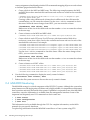
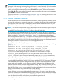
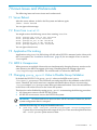
Figure 1-2 Server Pairs
Figure 1-2 shows typical wiring for server pairs.
IMPORTANT: If you are using MSA2000fc G1 (MSA2212fc), see (page 66) for important
information about cabling that can affect failover.
1.3.1.1 Server Memory Requirements
The Lustre Operations Manual section 3.1.6 discusses memory requirements for SFS servers. These
should be regarded as minimum memory requirements. Additional memory greatly increases
the performance of the system. HP requires a minimum of 4 GB for MGS and MDS servers, and
18
What's In This Version
minimum memory for OSS servers according to the following guidelines, based on the number
of OSTs connected to the OSS server pair, at a rate of 2 GB per OST:
•
8 GB:
— 2x [MSA2000fc + 1xJBOD] = 4xOSTs per OSS pair = 2xOST per OSS
•
16GB:
— 4x [MSA2000fc + 1xJBOD] = 8xOSTs per OSS pair = 4xOST per OSS
— 2x [MSA2000fc + 3xJBOD] = 8xOSTs per OSS pair = 4xOST per OSS
•
32 GB:
— 4x [MSA2000fc + 3xJBOD] = 16xOSTs per OSS pair = 8xOST per OSS
More memory for the servers increases performance and is recommended when budgets allow.
IMPORTANT: Memory requirements for HP SFS G3.2-0 have increased from previous versions.
Before deciding whether to upgrade to HP SFS G3.2-0, please determine whether additional
memory is needed for your systems. Insufficient memory can cause poor performance, or can
cause the system to become unresponsive and/or crash.
A new default feature called OSS Read Cache in Lustre V1.8 increases performance for read
intensive workloads at the expense of additional memory usage on the OSS servers. If you don't
have sufficient memory for proper operation of the OSS Read Cache feature, or don't want to
use the functionality, see the Lustre Operations Manual section 22.2.7.1 for instructions on disabling
the capability.
1.3.1.2 Fibre Channel Switch Zoning
If your Fibre Channel is configured with a single Fibre Channel switch connected to more than
one server node failover pair and its associated MSA storage devices, you must set up zoning
on the Fibre Channel switch. Most configurations are expected to require this zoning. The zoning
should be set up such that each server node failover pair only can see the MSA2000 storage
devices that are defined for it, similar to the logical view shown in Figure 1-1 (page 17). The
Fibre Channel ports for each server node pair, and its associated MSA storage devices should
be put into the same switch zone.
For the commands used to set up Fibre Channel switch zoning, see the documentation for your
specific Fibre Channel B-series switch available from:
http://www.hp.com/go/san
1.4 Server Security Policy
The HP Scalable File Share G3 servers run a generic Linux operating system. Security
considerations associated with the servers are the responsibility of the customer. HP strongly
recommends that access to the SFS G3 servers be restricted to administrative users only. Doing
so will limit or eliminate user access to the servers, thereby reducing potential security threats
and the need to apply security updates. For information on how to modify validation of user
credentials, see “Configuring User Credentials” (page 35).
HP provides security updates for all non-operating-system components delivered by HP as part
of the HP SFS G3 product distribution. This includes all rpm's delivered in
/opt/hp/sfs. Additionally, HP SFS G3 servers run a customized kernel which is modified to
provide Lustre support. Generic kernels cannot be used on the HP SFS G3 servers. For this reason,
HP also provides kernel security updates for critical vulnerabilities as defined by CentOS kernel
releases which are based on RedHat errata kernels. These kernel security patches are delivered
via ITRC along with installation instructions.
It is the customer's responsibility to monitor, download, and install user space security updates
for the Linux operating system installed on the SFS G3 servers, as deemed necessary, using
1.4 Server Security Policy
19
standard methods available for CentOS. CentOS security updates can be monitored by subscribing
to the CentOS Announce mailing list.
1.5 Release Notes
1.5.1 New and Changed Information in This Edition
•
•
•
•
•
•
•
CentOS 5.3 support on clients and servers (required on servers)
Lustre 1.8.0.1 support (required on servers)
OFED 1.4.1 support (required for IB servers)
Mellanox 10GbE MLNX_EN driver version 1.4.1 (required for 10 GigE servers)
InfiniBand Quad Data Rate (QDR) support
DL380 G6 server support (required for IB QDR)
The -c option to the gen_hb_config_files.pl script automatically copies the Heartbeat
configuration files to the servers and sets the appropriate permissions on the files. For more
information, see “Copying Files” (page 51).
For the new Luster 1.8 features, see:
http://wiki.lustre.org/index.php/Lustre_1.8
1.5.2 Bug Fixes
For the Luster 1.8 changelog (bug fixes), see:
http://wiki.lustre.org/index.php/Use:Change_Log_1.8
1.5.3 Known Issues
For more information about known issues and workarounds, see Chapter 7 (page 63).
20
What's In This Version
2 Installing and Configuring MSA Arrays
This chapter summarizes the installation and configuration steps for MSA2000fc arrays use in
HP SFS G3.2-0 systems.
2.1 Installation
For detailed instructions of how to set up and install the MSA arrays, see Chapter 4 of the HP
StorageWorks 2012fc Modular Smart Array User Guide on the HP website at:
http://bizsupport.austin.hp.com/bc/docs/support/SupportManual/c01394283/c01394283.pdf
2.2 Accessing the MSA CLI
You can use the CLI software, embedded in the controller modules, to configure, monitor, and
manage a storage system. CLI can be accessed using telnet over Ethernet. Alternatively, you can
use a terminal emulator if the management network is down. For information on setting up the
terminal emulator, see the HP StorageWorks 2000 Family Modular Smart Array CLI Reference Guide
on the HP website at:
http://bizsupport.austin.hp.com/bc/docs/support/SupportManual/c01505833/c01505833.pdf
NOTE: The MSA arrays must be connected to a server with HP SFS G3.2-0 software installed
as described in Chapter 3 (page 27) to use scripts to perform operations on multiple MSA arrays.
2.3 Using the CLI to Configure Multiple MSA Arrays
The CLI is used for managing a number of arrays in a large HP SFS configuration because it
enables scripted automation of tasks that must be performed on each array. CLI commands are
executed on an array by opening a telnet session from the management server to the array. The
provided script, /opt/hp/sfs/msa2000/msa2000cmd.pl, handles the details of opening a
telnet session on an array, executing a command, and closing the session. This operation is quick
enough to be practical in a script that repeats the command on each array. For a detailed
description of CLI commands, see the HP StorageWorks 2000 Family Modular Smart Array CLI
Reference Guide.
2.3.1 Configuring New Volumes
Only a subset of commands is needed to configure the arrays for use with HP SFS. To configure
new volumes on the storage arrays, follow these steps:
1.
2.
3.
4.
Power on all the enclosures.
Use the rescan command on the array controllers to discover all the attached enclosures
and drives.
Use the create vdisk command to create one vdisk from the disks of each storage
enclosure. For MGS and MDS storage, HP SFS uses RAID10 with 10 data drives and 2 spare
drives. For OST storage, HP SFS uses RAID6 with 9 data drives, 2 parity drives, and 1 hot
spare. The command is executed for each enclosure.
Use the create volume command to create a single volume occupying the full extent of
each vdisk. In HP SFS, one enclosure contains one vdisk, which contains one volume, which
becomes one Lustre Object Storage Target (OST).
To examine the configuration and status of all the arrays, use the show commands. For more
information about show commands, see the HP StorageWorks 2000 Family Modular Smart Array
CLI Reference Guide.
2.1 Installation
21
IMPORTANT: The size of a Lustre MDT or OST is limited to 8 TB. Therefore, any volume created
on the MSA2000 must be less than or equal to 8796 GB. If a vdisk is larger than 8796 GB, due to
the number and size of disks used, a volume less than or equal to 8796 GB must be created from
the vdisk.
2.3.2 Creating New Volumes
To create new volumes on a set of MSA2000 arrays, follow these steps:
1.
2.
Power on all the MSA2000 shelves.
Define an alias.
One way to execute commands on a set of arrays is to define a shell alias that calls
/opt/hp/sfs/msa2000/msa2000cmd.pl for each array. The alias defines a shell for-loop
which is terminated with ; done. For example:
# alias forallmsas='for NN in 'seq 101 2 119' ; do \
./msa2000cmd.pl 192.168.16.$NN'
In the above example, controller A of the first array has an IP address of 192.168.16.101,
controller B has the next IP address, and the rest of the arrays have consecutive IP addresses
up through 192.168.16.[119,120] on the last array. This command is only executed on one
controller of the pair.
For the command examples in this section, the MGS and MDS use the MSA2000 A controllers
assigned to IP addresses 192.168.16.101–103. The OSTs use the A controllers assigned to the
IP addresses 192.168.16.105–119. The vdisks and volumes created for MGS and MDS are not
the same as vdisks and volumes created for OSTs. So, for convenience, define an alias for
each set of MDS (MGS and MDS) and OST controllers.
# alias formdsmsas='for NN in 'seq 101 2 103' ; do ./msa2000cmd.pl 192.168.16.$NN'
# alias forostmsas='for NN in 'seq 105 2 119' ; do ./msa2000cmd.pl 192.168.16.$NN'
NOTE:
You may receive the following error if a controller is down:
# alias forallmsas='for NN in 'seq 109 2 115' ; do ./msa2000cmd.pl 192.168.16.$NN'
# forallmsas show disk 3 ; done
---------------------------------------------------On MSA2000 at 192.168.16.109 execute < show disk 3 >
ID Serial#
Vendor
Rev. State
Type Size(GB) Rate(Gb/s) SP
-----------------------------------------------------------------------------3
3LN4CJD700009836M9QQ
SEAGATE
0002 AVAIL
SAS
146
3.0
-----------------------------------------------------------------------------On MSA2000 at 192.168.16.111 execute < show disk 3 >
ID Serial#
Vendor
Rev. State
Type Size(GB) Rate(Gb/s) SP
-----------------------------------------------------------------------------3
3LN4DX5W00009835TQX9
SEAGATE
0002 AVAIL
SAS
146
3.0
-----------------------------------------------------------------------------On MSA2000 at 192.168.16.113 execute < show disk 3 >
problem connecting to "192.168.16.113", port 23: No route to host at ./msa2000cmd.pl line 12
---------------------------------------------------On MSA2000 at 192.168.16.115 execute < show disk 3 >
problem connecting to "192.168.16.115", port 23: No route to host at ./msa2000cmd.pl line 12
3.
Storage arrays consist of a controller enclosure with two controllers and up to three connected
disk drive enclosures. Each enclosure can contain up to 12 disks.
Use the rescan command to find all the enclosures and disks. For example:
# forallmsas rescan ; done
22
Installing and Configuring MSA Arrays
# forallmsas show disks ; done
The CLI syntax for specifying disks in enclosures differs based on the controller type used
in the array. The following vdisk and volume creation steps are organized by controller
types MSA2212fc and MSA2312fc, and provide examples of command-line syntax for
specifying drives. This assumes that all arrays in the system are using the same controller
type.
• MSA2212fc Controller
Disks are identified by SCSI ID. The first enclosure has disk IDs 0-11, the second has
16-27, the third has 32-43, and the fourth has 48-59.
•
MSA2312fc Controller
Disks are specified by enclosure ID and slot number. Enclosure IDs increment from 1.
Disk IDs increment from 1 in each enclosure. The first enclosure has disk IDs 1.1-12,
the second has 2.1-12, the third has 3.1-12, and the fourth has 4.1-12.
Depending on the order in which the controllers powered on, you might see different ranges
of disk numbers. If this occurs, run the rescan command again.
4.
If you have MSA2212fc controllers in your arrays, use the following commands to create
vdisks and volumes for each enclosure in all of the arrays. When creating volumes, all
volumes attached to a given MSA must be assigned sequential LUN numbers to ensure
correct assignment of multipath priorities.
a. Create vdisks in the MGS and MDS array. The following example assumes the MGS
and MDS do not have attached disk enclosures and creates one vdisk for the controller
enclosure. The disks 0-4 are mirrored by disks 5-9 in this configuration:
# formdsmsas create vdisk level raid10 disks 0-4:5-9 assigned-to a spare 10,11 mode offline vdisk1;
done
Creating vdisks using offline mode is faster, but in offline mode the vdisk must be
created before you can create the volume. Use the show vdisks command to check
the status. When the status changes from OFFL, you can create the volume.
# formdsmsas show vdisks; done
Make a note of the size of the vdisks and use that number <size> to create the volume
in the next step.
b.
Create volumes on the MDS and MDS vdisk.
# formdsmsas create volume vdisk vdisk1 size <size> mapping 0-1.11 volume1; done
c.
Create vdisks in each OST array. For OST arrays with one attached disk drive enclosure,
create two vdisks, one for the controller enclosure and one for the attached disk
enclosure. For example:
# forostmsas create vdisk level raid6 disks 0-10 assigned-to a spare 11 mode offline vdisk1; done
# forostmsas create vdisk level raid6 disks 16-26 assigned-to b spare 27 mode offline vdisk2; done
Use the show vdisks command to check the status. When the status changes from
OFFL, you can create the volume.
# forostmsas show vdisks; done
Make a note of the size of the vdisks and use that number <size> to create the volume
in the next step.
d.
Create volumes on all OST vdisks. In the following example, LUN numbers are 21 and
22.
# forostmsas create volume vdisk vdisk1 size <size> mapping 0-1.21 volume1; done
# forostmsas create volume vdisk vdisk2 size <size>
5.
mapping 0-1.22 volume2; done
If you have MSA2312fc controllers in your arrays, use the following commands to create
vdisks and volumes for each enclosure in all of the arrays. When creating volumes, all
volumes attached to a given MSA must be assigned sequential LUN numbers to ensure
2.3 Using the CLI to Configure Multiple MSA Arrays
23
correct assignment of multipath priorities. HP recommends mapping all ports to each volume
to facilitate proper hardware failover.
a. Create vdisks in the MGS and MDS array. The following example assumes the MGS
and MDS do not have attached disk enclosures and creates one vdisk for the controller
enclosure.
# formdsmsas create vdisk level raid10 disks 1.1-2:1.3-4:1.5-6:1.7-8:1.9-10 assigned-to a spare
1.11-12 mode offline vdisk1; done
Creating vdisks using offline mode is faster, but in offline mode the vdisk must be
created before you can create the volume. Use the show vdisks command to check
the status. When the status changes from OFFL, you can create the volume.
# formdsmsas show vdisks; done
Make a note of the size of the vdisks and use that number <size> to create the volume
in the next step.
b.
Create volumes on the MDS and MDS vdisk.
# formdsmsas create volume vdisk vdisk1 size <size> volume1 lun 31 ports a1,a2,b1,b2; done
c.
Create vdisks in each OST array. For OST arrays with three attached disk drive
enclosures, create four vdisks, one for the controller enclosure and one for each of the
attached disk enclosures. For example:
# forostmsas create vdisk level raid6 disks 1.1-11 assigned-to a spare 1.12 mode offline vdisk1; done
# forostmsas create vdisk level raid6 disks 2.1-11 assigned-to b spare 2.12 mode offline vdisk2; done
# forostmsas create vdisk level raid6 disks 3.1-11 assigned-to a spare 3.12 mode offline vdisk3; done
# forostmsas create vdisk level raid6 disks 4.1-11 assigned-to b spare 4.12 mode offline vdisk3; done
Use the show vdisks command to check the status. When the status changes from
OFFL, you can create the volume.
# forostmsas show vdisks; done
Make a note of the size of the vdisks and use that number <size> to create the volume
in the next step.
d.
6.
Create volumes on all OST vdisks.
# forostmsas create volume vdisk vdisk1 size <size> volume1 lun 41
ports a1,a2,b1,b2; done
# forostmsas create volume vdisk vdisk2 size <size> volume2 lun 42
ports a1,a2,b1,b2; done
# forostmsas create volume vdisk vdisk3 size <size> volume3 lun 43
ports a1,a2,b1,b2; done
# forostmsas create volume vdisk vdisk4 size <size> volume4 lun 44
ports a1,a2,b1,b2; done
Use the following command to display the newly created volumes:
# forostmsas show volumes; done
7.
Reboot the file system servers to discover the newly created volumes.
2.4 MSA2000 Monitoring
The MSA2000 storage is a critical component of the HP SFS G3 system. Although the system has
many features to avoid single points of failures and is highly reliable, it is important to understand
how to monitor and verify the health of the system. If problem is suspected on one of the MSA2000
controllers, extensive information is available from the management interfaces. Some of the
important and frequently used CLI commands to check status are:
•
•
•
# show events
# show configuration
# show frus
This information is also available through the GUI. For complete information, see the MSA
manuals for your specific hardware.
To upload log information from the MSA2000 controllers to a Linux system using FTP:
24
Installing and Configuring MSA Arrays
1.
Enable FTP on the MSA with the CLI command:
# set protocols ftp enable
2.
Use FTP from a Linux host to upload log files:
# ftp MSAIPaddress
3.
4.
Log in with the manage account and password.
ftp> get logs Linuxfilename
The MSA logs and configuration information will be saved to the Linuxfilename on your
Linux host. You might be asked to provide this information to the HP MSA support team.
2.4.1 email Notifications
The MSA controller can send electronic mail to a designated address when there is an event
requiring attention. MSA2212fc controllers configure event notification through the MSA GUI,
not through the command line. MSA2312fc controllers add CLI commands. This following
sections describe how to enable this functionality.
2.4.1.1 GUI Method
1.
2.
3.
4.
5.
6.
7.
8.
Start the MSA GUI by pointing a browser at http://MSAIPaddress and log in with the manage
username and password.
Select MANAGE→EVENT NOTIFICATION. In the initial notification summary screen, click
the button to enable email alerts, and check the boxes corresponding to the desired alert
levels (Informational, Warning, Critical).
Select Change Notification Settings.
Select Email Configuration on the left side.
Fill in up to four email addresses for notifications. If you want the mail to come from
SenderName@DomainName, enter Domain Name and Sender Name.
The address of the email server must also be configured. This address must be accessible to
the MSA based on the IP address and gateway configuration settings of the email server.
The email server can be one of the HP SFS servers, or another mail server already configured
on the network.
Check the Change Email Alerts Configuration box.
To test that your configuration, use the Send Test Email box. If it returns a success message
and the email is received by the designated address, you are finished with this MSA. If an
error message is returned, verify that your mail server configuration is correct as described
below.
2.4.1.2 CLI Method
MSA 2312fc controllers use the CLI command set email-parameters to configure email
alerts. The usage of the command is:
# set email-parameters server server domain domain email-list email-addresses notification-level
none|info|warn|crit [sender sender]
To verify the configuration, use the show email-parameters command. To send a test
message, use the test notification command.
2.4.1.3 Mail Server Configuration
The MSA can send email through an established mail server. HP SFS servers can also be set up
to relay mail from the MSA2000 controllers as follows:
2.4 MSA2000 Monitoring
25
1.
2.
Install the sendmail-cf RPM from your operating system distribution media, if it is not
already installed.
If you are running with a firewall, the sendmail firewall port 25 must be open by adding
the following line to /etc/sysconfig/iptables before the final COMMIT line:
-A RH-Firewall-1-INPUT -m state --state NEW -m tcp -p tcp --dport 25 -j ACCEPT
3.
Restart the firewall:
# service iptables restart
4.
5.
6.
Make sure a fully qualified host name for the server node is present in /etc/hosts.
To send mail to an email address non-local to the HP-SFS servers, domain name service on
the node must be correctly set up to access your default network SNMP mail server. This is
typically done by setting up the correct information in /etc/resolv.conf.
Add a line to the /etc/mail/access file for each MSA controller IP address. For example:
192.168.16.101 RELAY
7.
Add dnl to the /etc/mail/sendmail.mc file to allow non-localhost email.
dnl DAEMON_OPTIONS('Port=smtp,Addr=127.0.0.1, Name=MTA')dnl
8.
On some systems, you might need to specify an external mail server by removing dnl from
the following line and specifying the SMTP mail server:
define('SMART_HOST', 'smtp.your.provider')dnl
9. # cd /etc/mail
10. # make
11. # service sendmail restart
You should now be able to designate an HP SFS server as a mail server in the MSA configuration,
and it should work correctly. If there are problems, check the /var/log/maillog file for
debugging information. If you are using an existing mail server, you might need to follow a
procedure similar to that described above on the existing mail server. Work with your system
administrator to resolve any additional configuration modifications that might be required for
your specific local network and security configuration.
2.4.2 SNMP Monitoring
If there is an SNMP management system present on the network containing the MSA, the MSA
can report status information and traps through SNMP. On the MSA2000, this is controlled
primarily through the set snmp-parameters CLI command or GUI. To complete the setup
of SNMP monitoring, see the MSA2000 documentation and the documentation for your SNMP
management system.
26
Installing and Configuring MSA Arrays
3 Installing and Configuring HP SFS Software on Server
Nodes
This chapter provides information about installing and configuring HP SFS G3.2-0 software on
the Lustre file system server.
The following list is an overview of the installation and configuration procedure for file system
servers and clients. These steps are explained in detail in the following sections and chapters.
1. Update firmware.
2. Installation Phase 1
a. Choose an installation method.
• DVD/NFS Kickstart Procedure
• DVD/USB Drive Kickstart Procedure
• Network Install
b.
c.
d.
e.
3.
Edit the Kickstart template file with local information and copy it to the location specific
to the installation procedure.
Power on the server and Kickstart the OS and HP SFS G3.2-0 installation.
Run the install1.sh script if not run by Kickstart.
Reboot.
Installation Phase 2
a. Download patches, if any, from the HP IT Resource Center (ITRC), and follow the patch
installation instructions.
b. Run the install2.sh script.
• If you are using 10 GigE, run the install10GbE.sh script. For more information,
see “10 GigE Installation” (page 33).
c.
Reboot.
4.
Perform the following steps on each server node to complete the configuration:
a. Configure the management network interfaces if not configured by Kickstart.
b. Configure the InfiniBand or 10 GigE interconnect interface.
c. Create an etc/hosts file and copy to each server.
d. Configure pdsh.
e. Configure ntp if not configured by Kickstart.
f. Configure user access.
5.
When the configuration is complete, perform the following steps to create the Lustre file
system as described in Chapter 5 (page 45):
a. Create the Lustre file system.
b. Configure Heartbeat.
c. Start the Lustre file system.
6.
When the file system has been created, install the Lustre software on the clients and mount
the file system as described in Chapter 4 (page 41):
a. Install Lustre software on client nodes.
b. Mount the Lustre file system on client nodes.
The entire file system server installation process must be repeated for additional file system
server nodes. If the configuration consists of a large number of file system server nodes, you
might want to use a cluster installation and monitoring system like HP Insight Control
Environment for Linux (ICE-Linux) or HP Cluster Management Utility (CMU).
27
3.1 Supported Firmware
Follow the instructions in the documentation which was included with each hardware component
to ensure that you are running the latest qualified firmware versions. The associated hardware
documentation includes instructions for verifying and upgrading the firmware.
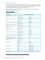
For the minimum firmware versions supported, see Table 3-1.
Upgrade the firmware versions, if necessary. You can download firmware from the HP IT
Resource Center on the HP website at:
http://www.itrc.hp.com
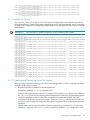
Table 3-1 Minimum Firmware Versions
Component
HP J4903A ProCurve Switch 2824
Minimum Firmware Version
I.10.43, 08/15/2007
Code Version
J200P39
Memory Controller
F300R22
Loader Version
15.010
Code Version
W420R56
Loader Version
12.013
MSA2212fc Enclosure Controller
Code Version
3201
MSA2212fc RAID Controller
Hardware
Hardware Version
LCA 56
CPLD Version
27
Expansion Shelf
Enclosure Controller
3023
Code Version
M110R01
Memory Controller
F300R22
Loader Version
19.008
Code Version
W441a01
Loader Version
12.015
MSA2312fc Enclosure Controller
Code Version
1036
MSA2312fc RAID Controller
Hardware
Hardware Version
56
CPLD Version
8
Kernel
2.6.14.2
Fabric OS
v6.1.0h
BootProm
4.6.6
BIOS
P56 1/24/2008
iLO2
1.78 4/23/2009
BIOS
P62 3/27/2009
iLO2
1.78 4/23/2009
MSA2212fc Storage Controller
MSA2212fc Management Controller
MSA2312fc Storage Controller
MSA2312fc Management Controller
SAN Switch
DL380 G5 Server
DL380 G6 Server
For InfiniBand firmware information, contact your HP representative. For more information,
see:
http://h20311.www2.hp.com/HPC/cache/595863-0-0-0-121.html
28
Installing and Configuring HP SFS Software on Server Nodes
3.2 Installation Requirements
A set of HP SFS G3.2-0 file system server nodes should be installed and connected by HP in
accordance with the HP SFS G3.2-0 hardware configuration requirements.
The file system server nodes use the CentOS 5.3 software as a base. The installation process is
driven by the CentOS 5.3 Kickstart process, which is used to ensure that required RPMs from
CentOS 5.3 are installed on the system.
NOTE:
CentOS 5.3 is available for download from the HP Software Depot at:
http://www.hp.com/go/softwaredepot
NOTE: Lustre does not support SELinux on servers or clients. SELinux is disabled in the
Kickstart template provided with HP SFS G3.2-0.
3.2.1 Kickstart Template Editing
A Kickstart template file called sfsg3DVD.cfg is supplied with HP SFS G3.2-0. You can find
this file in the top-level directory of the HP SFS G3.2-0 DVD, and on an installed system in
/opt/hp/sfs/scripts/sfsg3DVD.cfg. You must copy the sfsg3DVD.cfg file from the
DVD, edit it, and make it available during installation.
This file must be modified by the installer to do the following:
• Set up the time zone.
• Specify the system installation disk device and other disks to be ignored.
• Provide root password information.
IMPORTANT:
and/or fail.
You must make these edits, or the Kickstart process will halt, prompt for input,
You can also perform optional edits that make setting up the system easier, such as:
• Setting the system name
• Configuring network devices
• Configuring ntp servers
• Setting the system networking configuration and name
• Setting the name server and ntp configuration
While these are not strictly required, if they are not set up in Kickstart, you must manually set
them up after the system boots.
The areas to edit in the Kickstart file are flagged by the comment:
## Template ADD
Each line contains a variable name of the form %{text}. You must replace that variable with the
specific information for your system, and remove the ## Template ADD comment indicator. For
example:
## Template ADD timezone %{answer_timezone}
%{answer_timezone} must be replaced by your time zone, such as America/New_York
For example, the final edited line looks like:
timezone America/New_York
Descriptions of the remaining variables to edit follows:
## Template ADD rootpw %{answer_rootpw}
%{answer_rootpw} must be replaced by your root password, or the encrypted form from the
/etc/shadow file by using the --iscrypted option before the encrypted password.
3.2 Installation Requirements
29
The following optional, but recommended, line sets up an Ethernet network interface. More than
one Ethernet interface may be set up using additional network lines. The --hostname and
--nameserver specifications are needed only in one network line. For example, (on one line):
## Template ADD network --bootproto static --device %{prep_ext_nic} \
--ip %{prep _ext_ip} --netmask %{prep_ext_net} --gateway %{prep_ext_gw} \
--hostname %{host_name}.%{prep_ext_search} --nameserver %{prep_ext_dns}
%{prep_ext_nic} must be replaced by the Ethernet interface name. eth1 is recommended for
the external interface and eth0 for the internal interface.
%{prep_ext_ip} must be replaced by the interface IP address.
%{prep_ext_net} must be replaced by the interface netmask.
%{prep_ext_gw} must be replaced by the interface gateway IP address.
%{host_name} must be replaced by the desired host name.
%{prep_ext_search} must be replaced by the domain name.
%{prep_ext_dns} must be replaced by the DNS name server IP address or Fully Qualified
Domain Name (FQDN).
IMPORTANT: The InfiniBand IPoIB interface ib0 cannot be set up using this method, and must
be manually set up using the procedures “Configuration Instructions” (page 34).
In all the following lines, %{ks_harddrive} must be replaced by the installation device, usually
cciss/c0d0 for a DL380 server. The %{ks_ignoredisk} should list all other disk devices on the
system so they will be ignored during Kickstart. For a DL380 server, this variable should identify
all other disk devices detected such as cciss/c0d1,cciss/c0d2,sda,sdb,sdc,sdd,sde,sdf,sdg,sdh,...
For example:
##
##
##
##
##
##
Template
Template
Template
Template
Template
Template
ADD
ADD
ADD
ADD
ADD
ADD
bootloader --location=mbr --driveorder=%{ks_harddrive}
ignoredisk --drives=%{ks_ignoredisk}
clearpart --drives=%{ks_harddrive} --initlabel
part /boot --fstype ext3 --size=150 --ondisk=%{ks_harddrive}
part / --fstype ext3 --size=27991 --ondisk=%{ks_harddrive}
part swap --size=6144 --ondisk=%{ks_harddrive}
These Kickstart files are set up for a mirrored system disk. If your system does not support this,
you must adjust the disk partitioning accordingly.
The following optional, but recommended lines set up the name server and ntp server.
##
##
##
##
Template
Template
Template
Template
ADD
ADD
ADD
ADD
echo "search %{domain_name}" >/etc/resolv.conf
echo "nameserver %{nameserver_path}" >>/etc/resolv.conf
ntpdate %{ntp_server}
echo "server %{ntp_server}" >>/etc/ntp.conf
%{domain_name} should be replaced with the system domain name.
%{nameserver_path} should be replaced with the DNS nameserver address or FQDN.
%{ntp_server} should be replaced with the ntp server address or FQDN.
3.3 Installation Phase 1
3.3.1 DVD/NFS Kickstart Procedure
The recommended software installation method is to install CentOS 5.3 and the HP SFS G3.2-0
software using the DVD copies of both. The installation process begins by inserting the CentOS
5.3 DVD into the DVD drive of the DL380 server and powering on the server. At the boot prompt,
you must type the following on one command line, inserting your own specific networking
information for the node to be installed and the NFS location of the modified Kickstart file:
boot: linux ks=nfs:install_server_network_address:/install_server_nfs_path/sfsg3DVD.cfg
ksdevice=eth1 ip=filesystem_server_network_address netmask=local_netmask gateway=local_gateway
Where the network addresses, netmask, and paths are specific to your configuration.
30
Installing and Configuring HP SFS Software on Server Nodes
During the Kickstart post-installation phase, you are prompted to install the HP SFS G3.2-0 DVD
into the DVD drive:
Please insert the HP SFS G3.2-0 DVD and enter any key to continue:
After you insert the HP SFS G3.2-0 DVD and press enter, the Kickstart installs the HP SFS G3.2-0
software onto the system in the directory /opt/hp/sfs. Kickstart then runs the
/opt/hp/sfs/scripts/install1.sh script to perform the first part of the software
installation.
NOTE:
The output from Installation Phase 1 is contained in /var/log/postinstall.log.
After the Kickstart completes, the system reboots.
If for some reason, the Kickstart process does not install the HP SFS G3.2-0 software and run the
/opt/hp/sfs/scripts/install1.sh script automatically, you can manually load the
software onto the installed system, unpack it in /opt/hp/sfs, and then manually run the script.
For example, after inserting the HP SFS G3.2-0 DVD into the DVD drive:
# mount /dev/cdrom /mnt/cdrom
# mkdir -p /opt/hp/sfs
# cd /opt/hp/sfs
# tar zxvf /mnt/cdrom/hpsfs/SFSgen3.tgz
# ./scripts/install1.sh
Proceed to “Installation Phase 2” (page 33).
3.3.2 DVD/USB Drive Kickstart Procedure
You can also install without any network connection by putting the modified Kickstart file on a
USB drive.
On another system, if it has not already been done, you must create and mount a Linux file
system on the USB drive. After you insert the USB drive into the USB port, examine the dmesg
output to determine the USB drive device name. The USB drive name is the first unused
alphabetical device name of the form /dev/sd[a-z]1. There might be some /dev/sd* devices
on your system already, some of which may map to MSA2000 drives. In the examples below,
the device name is /dev/sda1, but on many systems it can be /dev/sdi1 or it might use some
other letter. Also, the device name cannot be the same on the system you use to copy the Kickstart
file to and the target system to be installed.
# mke2fs /dev/sda1
# mkdir /media/usbdisk
# mount /dev/sda1 /media/usbdisk
Next, copy the modified Kickstart file to the USB drive and unmount it. For example:
# cp sfsg3DVD.cfg /media/usbdisk
# umount /media/usbdisk
The installation is started with the CentOS 5.3 DVD and USB drive inserted into the target system.
In that case, the initial boot command is similar to:
boot: linux ks=hd:sda1:/sfsg3DVD.cfg
3.3 Installation Phase 1
31
NOTE: USB drives are not scanned before the installer reads the Kickstart file, so you are
prompted with a message indicating that the Kickstart file cannot be found. If you are sure that
the device you provided is correct, press Enter, and the installation proceeds. If you are not sure
which device the drive is mounted on, press Ctrl+Alt+F4 to display USB mount information.
Press Ctrl+Alt+F1 to return to the Kickstart file name prompt. Enter the correct device name, and
press Enter to continue the installation.
Proceed as directed in “DVD/NFS Kickstart Procedure” (page 30), inserting the HP SFS G3.2-0
DVD at the prompt and removing the USB drive before the system reboots.
3.3.3 Network Installation Procedure
As an alternative to the DVD installation described above, some experienced users may choose
to install the software over a network connection. A complete description of this method is not
provided here, and should only be attempted by those familiar with the procedure. See your
specific Linux system documentation to complete the process.
NOTE: The DL380 servers must be set up to network boot for this installation option. However,
all subsequent reboots of the servers, including the reboot after the install1.sh script has
completed (“Installation Phase 2” (page 33)) must be from the local disk.
In this case, you must obtain ISO image files for CentOS 5.3 and the HP SFS G3.2-0 software
DVD and install them on an NFS server in their network. You must also edit the Kickstart template
file as described in “Kickstart Template Editing” (page 29), using the network installation
Kickstart template file called sfsg3.cfg instead. This file has additional configuration parameters
to specify the network address of the installation server, the NFS directories, and paths containing
the CentOS 5.3 and HP SFS G3.2-0 DVD ISO image files. This sfsg3.cfg file can be found in
the top-level directory of the HP SFS G3.2-0 DVD image, and also in
/opt/hp/sfs/scripts/sfsg3.cfg on an installed system.
The following edits are required in addition to the edits described in “Kickstart Template Editing”
(page 29):
##
##
##
##
Template
Template
Template
Template
ADD
ADD
ADD
ADD
nfs --server=%{nfs_server} --dir=%{nfs_iso_path}
mount %{nfs_server}:%{post_image_dir} /mnt/nfs
cp /mnt/nfs/%{post_image} /mnt/sysimage/tmp
losetup /dev/loop2 /mnt/sysimage/tmp/%{post_image}
%{nfs_server} must be replaced by the installation NFS server address or FQDN.
%{nfs_iso_path} must be replaced by the NFS path to the CentOS 5.3 ISO directory.
%{post_image_dir} must be replaced by the NFS path to the HP SFS G3.2-0 ISO directory.
%{post_image} must be replaced by the name of the HP SFS G3.2-0 ISO file.
Each server node installed must be accessible over a network from an installation server that
contains the Kickstart file, the CentOS 5.3 ISO image, and the HP SFS G3.2-0 software ISO image.
This installation server must be configured as a DHCP server to network boot the file system
server nodes to be installed. For this to work, the MAC addresses of the DL380 server eth1
Ethernet interface must be obtained during the BIOS setup. These addresses must be put into
the /etc/dhcpd.conf file on the installation server to assign Ethernet addresses and network
boot the file system servers. See the standard Linux documentation for the proper procedure to
set up your installation server for DHCP and network booting.
The file system server installation starts with a CentOS 5.3 Kickstart install. If the installation
server has been set up to network boot the file system servers, the process starts by powering
on the file system server to be installed. When properly configured, the network boot first installs
Linux using the Kickstart parameters. The HP SFS G3.2-0 software, which must also be available
over the network, installs in the Kickstart post-installation phase, and the
/opt/hp/sfs/scripts/install1.sh script is run.
32
Installing and Configuring HP SFS Software on Server Nodes
NOTE:
The output from Installation Phase 1 is contained in /var/log/postinstall.log.
Proceed to “Installation Phase 2”.
3.4 Installation Phase 2
After the Kickstart and install1.sh have been run, the system reboots and you must log in
and complete the second phase of the HP SFS G3.2-0 software installation.
3.4.1 Patch Download and Installation Procedure
To download and install HP SFS patches, if any, from the ITRC website, follow this procedure:
1.
Create a temporary directory for the patch download.
# mkdir /home/patches
2.
Go to the ITRC website.
http://www.itrc.hp.com/
3.
4.
5.
6.
7.
8.
9.
10.
11.
12.
13.
14.
If you have not previously registered for the ITRC, choose Register from the menu on the
left. You will be assigned an ITRC User ID upon completion of the registration process. You
supply your own password. Remember this User ID and password because you must use
it every time you download a patch from the ITRC.
From the registration confirmation window, select the option to go directly to the ITRC
home page.
From the ITRC home page, select Patch database from the menu on the left.
Under Find Individual Patches, select Linux.
In step 1: Select vendor and version, select hpsfsg3 as the vendor and select the
appropriate version.
In step 2: How would you like to search?, select Browse Patch List.
In step 4 Results per page?, select all.
Click search>> to begin the search.
Select all the available patches and click add to selected patch list.
Click download selected.
Choose the format and click download>>. Download all available patches into the temporary
directory you created.
Follow the patch installation instructions in the README file for each patch. See the Patch
Support Bulletin for more details, if available.
3.4.2 Run the install2.sh Script
Continue the installation by running the /opt/hp/sfs/scripts/install2.sh script
provided. The system must be rebooted again, and you can proceed with system configuration
tasks as described in “Configuration Instructions” (page 34).
NOTE: You might receive errors when running install2. They can be ignored. See “Errors
from install2” (page 63) for more information.
3.4.3 10 GigE Installation
If your system uses 10 GigE instead of InfiniBand, you must install the Mellanox 10 GigE drivers.
3.4 Installation Phase 2
33
IMPORTANT: This step must be performed for 10 GigE systems only. Do not use this process
on InfiniBand systems.
If your system uses Mellanox ConnectX HCAs in 10 GigE mode, HP recommends that you
upgrade the HCA board firmware before installing the Mellanox 10 GigE driver. If the existing
board firmware revision is outdated, you might encounter errors if you upgrade the firmware
after the Mellanox 10 GigE drivers are installed. Use the mstflint tool to check the firmware
version and upgrade to the minimum recommended version 2.6 as follows:
# mstflint -d 08:00.0 q
Image type:
ConnectX
FW Version:
2.6.0
Device ID:
25418
Chip Revision:
A0
Description:
Node
Port1
Port2
Sys image
GUIDs:
001a4bffff0cd124 001a4bffff0cd125 001a4bffff0cd126 001a4bffff0
MACs:
001a4b0cd125
001a4b0cd126
Board ID:
(HP_09D0000001)
VSD:
PSID:
HP_09D0000001
# mstflint -d 08:00.0 -i fw-25408-2_6_000-448397-B21_matt.bin -nofs burn
To ensure the correct firmware version and files for your boards, obtain firmware files from your
HP representative.
Run the following script:
# /opt/hp/sfs/scripts/install10GbE.sh
This script removes the OFED InfiniBand drivers and installs the Mellanox 10 GigE drivers. After
the script completes, the system must be rebooted for the 10 GigE drivers to be operational.
3.5 Configuration Instructions
After the HP SFS G3.2-0 software has been installed, some additional configuration steps are
needed. These steps include the following:
IMPORTANT: HP SFS G3.1-0 and later require a valid license. For license installation instructions,
see Chapter 6 (page 61).
•
•
•
•
•
Configuring network interfaces for Ethernet and InfiniBand or 10 GigE
Creating the /etc/hosts file and propagating it to each node
Configuring the pdsh command for file system cluster-wide operations
Configuring user credentials
Verifying digital signatures (optional)
3.5.1 Configuring Ethernet and InfiniBand or 10 GigE Interfaces
Ethernet and InfiniBand IPoIB ib0 interface addresses must be configured, if not already
configured with network statements in the Kickstart file. Use the CentOS GUI, enter the
system-config-network command, or edit
/etc/sysconfig/network-scripts/ifcfg-xxx files.
The IP addresses and netmasks for the InfiniBand interfaces should be chosen carefully to allow
the file system server nodes to communicate with the client nodes.
The system name, if not already set by the Kickstart procedure, must be set by editing the
/etc/sysconfig/network file as follows:
HOSTNAME=mynode1
34
Installing and Configuring HP SFS Software on Server Nodes
3.5.2 Creating the /etc/hosts file
Create an /etc/hosts file with the names and IP addresses of all the Ethernet interfaces on
each system in the file system cluster, including the following:
• Internal interfaces
• External interface
• iLO interfaces
• InfiniBand or 10 GigE interfaces
• Interfaces to the Fibre Channel switches
• MSA2000 controllers
• InfiniBand switches
• Client nodes (optional)
Propagate this file should be to all nodes in the file system cluster.
3.5.3 Configuring pdsh
The pdsh command enables parallel shell commands to be run across the file system cluster.
The pdsh RPMs are installed by the HP SFS G3.2-0 software installation process, but some
additional steps are needed to enable passwordless pdsh and ssh access across the file system
cluster.
1. Put all host names in /opt/hptc/pdsh/nodes.
2. Verify the host names are also defined with their IP addresses in/etc/hosts.
3. Append /root/.ssh/id_rsa.pub from the node where pdsh is run to
/root/.ssh/authorized_keys on each node.
4. Enter the following command:
# echo "StrictHostKeyChecking no" >> /root/.ssh/config
This completes the process to run pdsh from one node. Repeat the procedure for each additional
node you want to use for pdsh.
3.5.4 Configuring ntp
The Network Time Protocol (ntp) should be configured to synchronize the time among all the
Lustre file system servers and the client nodes. This is primarily to facilitate the coordination of
time stamps in system log files to easily trace problems. This should have been performed with
appropriate editing to the initial Kickstart configuration file. But if it is incorrect, manually edit
the /etc/ntp.conf file and restart the ntpd service.
3.5.5 Configuring User Credentials
For proper operation, the Lustre file system requires the same User IDs (UIDs) and Group IDs
(GIDs) on all file system clients. The simplest way to accomplish this is with identical
/etc/passwd and /etc/group files across all the client nodes, but there are other user
authentication methods like Network Information Services (NIS) or LDAP.
By default, Lustre file systems are created with the capability to support Linux file system group
access semantics for secondary user groups. This behavior requires that UIDs and GIDs are
known to the file system server node providing the MDS service, and also the backup MDS node
in a failover configuration. When using standard Linux user authorization, you can do this by
adding the lines with UID information from the client /etc/passwd file and lines with GID
information from the client /etc/group file to the /etc/passwd and /etc/group files on
the MDS and backup MDS nodes. This allows the MDS to access the GID and UID information,
but does not provide direct user login access to the file system server nodes. If other user
authentication methods like NIS or LDAP are used, follow the procedures specific to those
methods to provide the user and group information to the MDS and backup MDS nodes without
3.5 Configuration Instructions
35
enabling direct user login access to the file system server nodes. In particular, the shadow
password information should not be provided through NIS or LDAP.
IMPORTANT:
HP requires that users do not have direct login access to the file system servers.
If support for secondary user groups is not desired, or to avoid the server configuration
requirements above, the Lustre file system can be created so that it does not require user credential
information. The Lustre method for validating user credentials can be modified in two ways,
depending on whether the file system has already been created. The preferred and easier method
is to do this before the file system is created, using step 1 below.
1. Before the file system is created, specify "mdt.group_upcall=NONE" in the file system's CSV
file, as shown in the example in “Generating Heartbeat Configuration Files Automatically”
(page 49).
2. After the file system is created, use the procedure outlined in “Changing group_upcall
Value to Disable Group Validation” (page 63).
3.5.6 Verifying Digital Signatures (optional)
Verifying digital signatures is an optional procedure for customers to verify that the contents of
the ISO image are supplied by HP. This procedure is not required.
Two keys can be imported on the system. One key is the HP Public Key, which is used to verify
the complete contents of the HP SFS image. The other key is imported into the rpm database to
verify the digital key signatures of the signed rpms.
3.5.6.1 Verifying the HP Public Key (optional)
To verify the digital signature of the contents of the ISO image, the HP Public Key must be
imported to the user's gpg key ring. Use the following commands to import the HP Public Key:
# cd <root-of-SFS-image>/signatures
# gpg --import *.pub
Use the following commands to verify the digital contents of the ISO image:
# cd <root-of-SFS-image>/
# gpg --verify Manifest.md5.sig Manifest.md5
The following is a sample output of importing the Public key:
# mkdir -p /mnt/loop
# mount -o loop "HPSFSG3-ISO_FILENAME".iso /mnt/loop/
# cd /mnt/loop/
# gpg --import /mnt/loop/signatures/*.pub
gpg: key 2689B887: public key "Hewlett-Packard Company (HP Codesigning Service)" imported
gpg: Total number processed: 1
gpg:
imported: 1
And the verification of the digital signature:
# gpg --verify Manifest.md5.sig Manifest.md5
gpg: Signature made Tue 10 Feb 2009 08:51:56 AM EST using DSA key ID 2689B887
gpg: Good signature from "Hewlett-Packard Company (HP Codesigning Service)"
gpg: WARNING: This key is not certified with a trusted signature!
gpg:
There is no indication that the signature belongs to the owner.
Primary key fingerprint: FB41 0E68 CEDF 95D0 6681 1E95 527B C53A 2689 B887
3.5.6.2 Verifying the Signed RPMs (optional)
HP recommends importing the HP Public Key to the RPM database. Use the following command
as root to import this public key to the RPM database:
# rpm --import <root-of-SFS-image>/signatures/*.pub
36
Installing and Configuring HP SFS Software on Server Nodes
This import command should be performed by root on each system that installs signed RPM
packages.
3.6 Upgrade Installation
In some situations you may upgrade an HP SFS system running an older version of HP SFS
software to the most recent version of HP SFS software.
Upgrades can be as simple as updating a few RPMs, as in the case of some patches from HP SFS
G3 support, or as complex as a complete reinstallation of the server node. The upgrade of a major
or minor HP SFS release, such as from HP SFS G3.0-0 to HP SFS G3.2-0, or HP SFS G3.1-0 to HP
SFS G3.2-0, requires a complete Linux reinstallation of the server node since the underlying
operating system components change.
If you are upgrading from version 2.3, contact your HP representative for details about upgrade
support for both servers and clients.
If you are upgrading from one version of HP SFS G3 to a more recent version, follow the general
guidelines that follow.
IMPORTANT: All existing file system data must be backed up before attempting an upgrade.
HP is not responsible for the loss of any file system data during an upgrade.
The safest and recommended method for performing an upgrade is to first unmount all clients,
then stop all file system servers before updating any software. Depending on the specific upgrade
instructions, you may need to save certain system configuration files for later restoration. After
the file system server software is upgraded and the configuration is restored, bring the file system
back up. At this point, the client system software can be upgraded if applicable, and the file
system can be remounted on the clients.
3.6.1 Rolling Upgrades
If you must keep the file system online for clients during an upgrade, a "rolling" upgrade
procedure is possible on an HP SFS G3 system with properly configured failover. As file system
servers are upgraded, the file system remains available to clients. However, client recovery delays
(typically around 5 minutes long) occur after each server configuration change or failover
operation. Additional risk is present with higher levels of client activity during the upgrade
procedure, and the procedure is not recommended when there is critical long running client
application activity underway.
Also, please note any rolling upgrade restrictions. Major system configuration changes, such as
changing system interconnect type, or changing system topology are not allowed during rolling
upgrades. For general rolling upgrade guidelines, see the Lustre 1.8 Operations Manual
(http://manual.lustre.org/images/7/7f/820-3681_v1_1.pdf) section 13.2.2. For upgrade instructions
pertaining to the specific releases you are upgrading between, see the “Upgrading Lustre”
chapter.
NOTE: The same basic procedure, as outlined below, is followed for both non-rolling and
rolling upgrades. In the case of a non-rolling upgrade, since the file system is already unmounted
and stopped, steps 1, and 8 through 13 are not required. After all server nodes are upgraded for
a non-rolling upgrade, restart the file system as described in “Starting the File System” (page 53).
Follow any additional instructions you may have received from HP SFS G3 support concerning
the upgrade you are performing.
In general, a rolling upgrade procedure is performed based on failover pairs of server nodes. A
rolling upgrade must start with the MGS/MDS failover pairs, followed by successive OST pairs.
For each failover pair, the procedure is:
3.6 Upgrade Installation
37
1.
For the first member of the failover pair, stop the Heartbeat service to migrate the Lustre
file system components from this node to its failover pair node.
# chkconfig heartbeat off
# service heartbeat stop
At this point, the node is no longer serving the Lustre file system and can be upgraded. The
specific procedures will vary depending on the type of upgrade to be performed.
2.
In the case of a complete server reinstallation, save any server specific configuration files
that will need to be restored or referenced later. Those files include, but are not limited to:
• /etc/fstab
• /etc/hosts
• /etc/ha.d/ha.cf
• /etc/ha.d/haresources
• /etc/ha.d/authkeys
• /etc/modprobe.conf
• /etc/ntp.conf
• /etc/resolv.conf
• /etc/sysconfig/network
• /etc/sysconfig/network-scripts/ifcfg-ib0
• /etc/sysconfig/network-scripts/ifcfg-eth*
• /opt/hptc/pdsh/nodes
• /root/anaconda-ks.cfg
• /var/flexlm/license.lic
• /var/lib/heartbeat/crm/cib.xml
• /var/lib/multipath/bindings
• The CSV file containing the definition of your file system as used by the lustre_config
and gen_hb_config_files.pl programs.
• The CSV file containing the definition of the ILOs on your file system as used by the
gen_hb_config_files.pl program.
• The Kickstart file used to install this node.
• The /mnt mount-points for the Lustre file system.
Many of these files are available from other server nodes in the cluster, or from the failover
pair node in the case of the Heartbeat configuration files. Other files may be re-created
automatically by Kickstart.
3.
In the case of a complete node reinstallation, follow the general instructions in Chapter 3
(page 27).
For a patch update from HP SFS G3 support, follow the specific instructions from HP SFS
G3 support for this upgrade.
4.
If applicable, restore the files saved in step 2.
Please note that some files should not be restored in their entirety. Only the HP SFS specific
parts of the older files should be restored. For example:
• /etc/fstab — Only the HP SFS mount lines
• /etc/modprobe.conf — Only the SFS added lines, for example:
# start lustre config
# Lustre module options added automatically by lc_modprobe
options lnet networks=o2ib0
# end lustre config
5.
38
Reboot as necessary.
Installing and Configuring HP SFS Software on Server Nodes
6.
For the upgrade from SFS G3.0-0 to G3.1-0 or SFS G3.2-0, you must re-create the Heartbeat
configuration files to account for licensing. For the details, see “Configuration Files” (page 49).
For other upgrades, the previously saved Heartbeat files can be restored or re-created from
the CSV files.
IMPORTANT: HP SFS G3.2-0 requires a valid license. For license installation instructions,
see Chapter 6 (page 61).
NOTE: If you upgrade the MGS or MDS servers, you must also install the license files and
start the license servers as described in Chapter 6 (page 61).
7.
Verify that the system is properly configured. For example:
• /var/lib/heartbeat/crm/cib.xml — Verify the owner is hacluster and the group
is haclient as described in “Things to Double-Check” (page 52).
• /etc/ha.d/authkeys — Verify permission is 600 as described in “Things to
Double-Check” (page 52).
• /var/lib/multipath/bindings — Run the multipath -F and multipath -v0
commands to re-create the multipath configuration.
• Verify the Lustre file system mount-points are re-created manually.
• Bring any Ethernet or InfiniBand interfaces back up by restoring the respective ifcfg
file, and using ifup, if required.
8.
Restart the Heartbeat service.
# service heartbeat start
# chkconfig heartbeat on
Lustre components that are served primarily by this node are restored to this node.
9.
For rolling upgrades, if the Heartbeat files are re-generated, install the new cib.xml file
using the following command:
# cibadmin -R -x <new cib.xml file>
10. Run the crm_mon utility on both nodes of the failover pair and verify that no errors are
reported.
11. Verify that the file system is operating properly.
12. Repeat the process with the other member of the failover pair.
13. After both members of a failover pair are upgraded, repeat the procedure on the next failover
pair until all failover pairs are upgraded.
3.6.2 Client Upgrades
After all the file system servers are upgraded, clients can be upgraded if applicable. This procedure
depends on the types of clients and client management software present on the clients. In general,
unmount the file system on a client. Upgrade the software using the client installation information
in Chapter 4 (page 41), with specific instructions for this upgrade. Reboot as necessary. Remount
the file system and verify that the system is operating properly.
3.6 Upgrade Installation
39
40
4 Installing and Configuring HP SFS Software on Client
Nodes
This chapter provides information about installing and configuring HP SFS G3.2-0 software on
client nodes running CentOS 5.3, RHEL5U3, SLES10 SP2, and HP XC V4.0.
4.1 Installation Requirements
HP SFS G3.2-0 software supports file system clients running CentOS 5.3/RHEL5U3 and SLES10
SP2, as well as the HP XC V4.0 cluster clients. Customers using HP XC V4.0 clients should obtain
HP SFS client software and instructions from the HP XC V4.0 support team. The HP SFS G3.2-0
server software image contains the latest supported Lustre client RPMs for the other systems in
the /opt/hp/sfs/lustre/clients subdirectory. Use the correct type for your system.
4.1.1 Client Operating System and Interconnect Software Requirements
There are many methods for installing and configuring client systems with Linux operating
system software and interconnect software. HP SFS G3 does not require any specific method.
However, client systems must have the following:
• A supported version of Linux installed
• Any required add-on interconnect software installed
• An interconnect interface configured with an IP address that can access the HP SFS G3 server
cluster
• SELinux must be disabled.
This installation and configuration must be performed on each client system in accordance with
the capabilities of your client cluster software.
4.1.2 InfiniBand Clients
A client using InfiniBand to connect to the HP SFS servers needs to have the OFED software
version 1.4.1 installed and configured. Some Linux distributions have a version of OFED included,
if it has been preselected for installation.
NOTE: For interoperability with HP SFS G3.2-0, clients should be updated to OFED 1.4.1.
Clients at OFED 1.3 should work, but are not officially supported.
The HP SFS G3.2-0 server software image also contains the kernel-ib and kernel-ib-devel OFED
InfiniBand driver RPMs for the supported clients in the /opt/hp/sfs/lustre/clients
subdirectory, which can be optionally installed. Some customers may obtain a version of OFED
from their InfiniBand switch vendor. OFED source code can be downloaded from
www.openfabrics.org. You can also copy it from the HP SFS G3.2-0 server software image file
/opt/hp/sfs/SRPMS/OFED-1.4.1.tgz and build it for a different client system. In each of
these cases, see the documentation available from the selected source to install, build, and
configure the OFED software.
Configure the InfiniBand ib0 interface with an IP address that can access the HP SFS G3.2-0 server
using one of the methods described in “Configuring Ethernet and InfiniBand or 10 GigE Interfaces”
(page 34).
4.1.3 10 GigE Clients
Clients connecting to HP SFS G3.2-0 servers running 10 GigE can use Ethernet interfaces running
at 1 or 10 Gigabit/s speeds. Normally, clients using 1 Gigabit/s Ethernet interfaces will not need
any additional add-on driver software. Those interfaces will be supported by the installed Linux
distribution.
4.1 Installation Requirements
41
If the client is using the HP recommended 10 GigE ConnectX cards from Mellanox, the ConnectX
EN drivers must be installed. These drivers can be downloaded from www.mellanox.com, or
copied from the HP SFS G3.2-0 server software image in the
/opt/hp/sfs/ofed/mlnx_en-1.4.1 subdirectory. Copy that software to the client system
and install it using the supplied install.sh script. See the included README.txt and release notes
as necessary.
Configure the selected Ethernet interface with an IP address that can access the HP SFS G3.2-0
server using one of the methods described in “Configuring Ethernet and InfiniBand or 10 GigE
Interfaces” (page 34).
4.2 Installation Instructions
The following installation instructions are for a CentOS 5.3/RHEL5U3 system. The other systems
are similar, but use the correct Lustre client RPMs for your system type from the HP SFS G3.2-0
software tarball /opt/hp/sfs/lustre/client directory.
The Lustre client RPMs that are provided with HP SFS G3.2-0 are for use with CentOS
5.3/RHEL5U3 kernel version 2.6.18_128.1.6.e15. If your client is not running this kernel, you need
to either update your client to this kernel or rebuild the Lustre RPMs to match the kernel you
have using the instructions in “CentOS 5.3/RHEL5U3 Custom Client Build Procedure” (page 43).
You can determine what kernel you are running by using the uname -r command.
1.
Install the required Lustre RPMs for the kernel version 2.6.18_128.1.6.e15 Enter the following
command on one line:
# rpm -Uvh lustre-client1.8.0.1-2.6.18_128.1.6.el5_lustre.1.8.0.1smp.x86_64.rpm \
lustre-client-modules-1.8.0.1-2.6.18_128.1.6.el5_lustre.1.8.0.1smp.x86_64.rpm
For custom-built client RPMs, the RPM names are slightly different. In this case, enter the
following command on one line:
# rpm -Uvh lustre-1.8.0.1-2.6.18_53.1.21.el5.6hp_*.x86_64.rpm \
lustre-modules-1.8.0.1-2.6.18_53.1.21.el5.6hp_*.x86_64.rpm \
lustre-tests-1.8.0.1-2.6.18_53.1.21.el5.6hp_*.x86_64.rpm
2.
3.
Run the depmod command to ensure Lustre modules are loaded at boot.
For InfiniBand systems, add the following line to /etc/modprobe.conf:
options lnet networks=o2ib0
For 10 GigE systems, add the following line to /etc/modprobe.conf:
options lnet networks=tcp(eth2)
In this example, eth2 is the Ethernet interface that is used to communicate with the HP SFS
system.
4.
Create the mount-point to use for the file system. The following example uses a Lustre file
system called testfs, as defined in “Creating a Lustre File System” (page 45). It also uses
a client mount-point called /testfs. For example:
# mkdir /testfs
NOTE: The file system cannot be mounted by the clients until the file system is created
and started on the servers. For more information, see Chapter 5 (page 45).
5.
For InfiniBand systems, to automatically mount the Lustre file system after reboot, add the
following line to /etc/fstab:
172.31.80.1@o2ib:172.31.80.2@o2ib:/testfs /testfs lustre _netdev,rw,flock 0 0
42
Installing and Configuring HP SFS Software on Client Nodes
NOTE: The network addresses shown above are the InfiniBand IPoIB ib0 interfaces for the
HP SFS G3.2-0 Management Server (MGS) node, and the MGS failover node which must be
accessible from the client system by being connected to the same InfiniBand fabric and with
a compatible IPoIB IP address and netmask.
For 10 GigE systems, to automatically mount the Lustre file system after reboot, add the
following line to /etc/fstab:
172.31.80.1@tcp:172.31.80.2@tcp:/testfs /testfs lustre _netdev,rw,flock 0 0
6.
7.
8.
9.
Reboot the node and the Lustre file system is mounted on /testfs.
Repeat steps 1 through 6 for additional client nodes, using the appropriate node replication
or installation tools available on your client cluster.
After all the nodes are rebooted, the Lustre file system is mounted on /testfs on all nodes.
You can also mount and unmount the file system on the clients using the mount and umount
commands. For example:
# mount /testfs
# umount /testfs
4.3 Custom Client Build Procedures
If the client system kernel does not match the provided Lustre client RPMs exactly, they will not
install or operate properly. Use the following procedures to build Lustre client RPMs that match
a different kernel. Lustre 1.8.0.1 supports client kernels at a minimum level of RHEL4U5, SLES10,
and 2.6.15 or later. The Lustre client is "patchless", meaning the client kernel does not require
Lustre patches, and must not contain Lustre patches older than the current Lustre client version.
NOTE:
Building your own clients may produce a client that has not been qualified by HP.
4.3.1 CentOS 5.3/RHEL5U3 Custom Client Build Procedure
Additional RPMs from CentOS 5.3 or the RHEL5U3 DVD may be necessary to build Lustre.
These RPMs may include, but are not limited to the following:
•
•
•
•
•
•
elfutils
elfutils-libelf-devel
elfutils-libs
rpm
rpm-build
kernel-ib-devel (for InfiniBand systems)
1.
Install the Lustre source RPM as provided on the HP SFS G3.2-0 software tarball in the
/opt/hp/sfs/SRPMS directory. Enter the following command on one line:
# rpm -ivh lustre-source-1.8.0.1-2.6.18_128.1.6.el5_lustre.1.8.0.1smp.x86_64.rpm
2.
Change directories:
# cd /usr/src/lustre-1.8.0.1
3.
Run the following command on one line:
NOTE:
The --with-o2ib option should be used for InfiniBand systems only.
# ./configure --with-linux=/usr/src/kernels/<kernel to configure with> \
--with-o2ib=/usr/src/ofa_kernel
4.3 Custom Client Build Procedures
43
4.
Run the following command:
# make rpms 2>&1 | tee make.log
5.
When successfully completed, the newly built RPMs are available in
/usr/src/redhat/RPMS/x86_64. Proceed to “Installation Instructions” (page 42).
4.3.2 SLES10 SP2 Custom Client Build Procedure
Additional RPMs from the SLES10 SP2 DVD may be necessary to build Lustre. These RPMs may
include, but are not limited to the following:
• expect
• gcc
• kernel-source-xxx RPM to go with the installed kernel
1.
Install the Lustre source RPM as provided on the HP SFS G3.2-0 software tarball in the
/opt/hp/sfs/SRPMS directory. Enter the following command on one line:
# rpm -ivh lustre-source-1.8.0.1-2.6.18_128.1.6.el5_lustre.1.8.0.1smp.x86_64.rpm
2.
Change directories:
# cd /usr/src/linux-xxx
3.
4.
Copy in the /boot/config-xxx for the running/target kernel, and name it .config.
Run the following:
# make oldconfig
5.
Change directories:
# cd /usr/src/lustre-xxx
6.
Configure the Lustre build. For example, on one command line (replacing with different
versions if needed):
NOTE:
The --with-o2ib option should be used for InfiniBand systems only.
# ./configure --with-linux=/usr/src/linux-2.6.16.46-0.12/ \
--with-linux-obj=/usr/src/linux-2.6.16.46-0.12-obj/x86_64/smp \
--with-o2ib=/usr/src/ofa_kernel
7.
Run the following command:
# make rpms 2>&1 | tee make.log
8.
9.
When successfully completed, the newly built RPMs are available in
/usr/src/packages/RPMS/x86_64. Install them according to the “Installation
Instructions” (page 42).
For InfiniBand systems, add the following line to /etc/modprobe.conf.local:
options lnet networks=o2ib0
For 10 GigE systems, add the following line to /etc/modprobe.conf:
options lnet networks=tcp(eth2)
In this example, eth2 is the Ethernet interface that is used to communicate with the HP SFS
system.
44
Installing and Configuring HP SFS Software on Client Nodes
5 Using HP SFS Software
This chapter provides information about creating, configuring, and using the file system.
5.1 Creating a Lustre File System
The first required step is to create the Lustre file system configuration. At the low level, this is
achieved through the use of the mkfs.lustre command. However, HP recommends the use
of the lustre_config command as described in section 6.1.2.3 of the Lustre 1.8 Operations
Manual. This command requires that you create a CSV file which contains the configuration
information for your system that defines the file system components on each file system server.
5.1.1 Creating the Lustre Configuration CSV File
See the example CSV file provided in the HP SFS G3.2-0 software
/opt/hp/sfs/scripts/testfs.csv tarball and modify with your system-specific
configuration. The host name as returned by uname -n is used in column1, but the InfiniBand
IPoIB interface name is used in the NID specifications for the MGS node and failover node.
For 10 GigE interconnect systems, an example CSV file named
/opt/hp/sfs/scripts/testfs10GbE.csv is provided. Note the difference in the lnet
network specification and NID specifications.
NOTE:
The lustre_config program does not allow hyphens in host names or NID names.
The CSV files that define the Lustre file system configuration and iLO information must be in
UNIX (Linux) mode, not DOS mode. The example files provided as part of the HP SFS G3.2-0
software kit are in UNIX mode. These files might get converted to DOS mode if they are
manipulated, for example with Windows Excel. To convert a file from DOS to UNIX mode, use
a command similar to:
# dos2unix -n oldfile newfile
For the lustre_config program to work, passwordless ssh must be functional between file
system server nodes. This should have been done during Installation Phase 2. See “Configuring
pdsh” (page 35).
The provided CSV file and procedure assumes you have used the HP recommended configuration
with the MGS and MDS nodes as a failover pair, and additional pairs of OSS nodes where each
pair has access to a common set of MSA2000 storage devices.
To determine the multipath storage devices seen by each node that are available for use by Lustre
file system components, use the following command:
# ls /dev/mapper/mpath*
/dev/mapper/mpath4 /dev/mapper/mpath5 /dev/mapper/mpath6
/dev/mapper/mpath7
There should be one mpath device for each MSA2000 storage shelf. A properly configured pair
of nodes should see the same mpath devices. Enforce this by making sure that the
/var/lib/multipath/bindings file is the same for each failover pair of nodes. After the file
is copied from one node to another, the multipath mappings can be removed with the command:
multipath -F
They can be regenerated using the new bindings file with the command:
multipath -v0
Or the node can be rebooted.
These are the devices available to the Lustre configuration CSV file for use by mgs, mdt, and ost.
5.1 Creating a Lustre File System
45
To see the multipath configuration, use the following command. Output will be similar to the
example shown below:
# multipath -ll
mpath7 (3600c0ff000d547b5b0c95f4801000000) dm-5 HP,MSA2212fc
[size=4.1T][features=1 queue_if_no_path][hwhandler=0]
\_ round-robin 0 [prio=20][active]
\_ 0:0:3:5 sdd 8:48 [active][ready]
\_ 1:0:3:5 sdh 8:112 [active][ready]
mpath6 (3600c0ff000d548aa1cca5f4801000000) dm-4 HP,MSA2212fc
[size=4.1T][features=1 queue_if_no_path][hwhandler=0]
\_ round-robin 0 [prio=20][active]
\_ 0:0:2:6 sdc 8:32 [active][ready]
\_ 1:0:2:6 sdg 8:96 [active][ready]
mpath5 (3600c0ff000d5455bc8c95f4801000000) dm-3 HP,MSA2212fc
[size=4.1T][features=1 queue_if_no_path][hwhandler=0]
\_ round-robin 0 [prio=50][active]
\_ 1:0:1:5 sdf 8:80 [active][ready]
\_ round-robin 0 [prio=10][enabled]
\_ 0:0:1:5 sdb 8:16 [active][ready]
mpath4 (3600c0ff000d5467634ca5f4801000000) dm-2 HP,MSA2212fc
[size=4.1T][features=1 queue_if_no_path][hwhandler=0]
\_ round-robin 0 [prio=50][active]
\_ 0:0:0:6 sda 8:0
[active][ready]
\_ round-robin 0 [prio=10][enabled]
\_ 1:0:0:6 sde 8:64 [active][ready]
In the following example, there are an MGS (node1), an MDS (node2), and only a single OSS
pair, (node3 and node4). Each OSS has four OSTs. The Lustre file system is called testfs. During
normal operation, mount the Lustre roles as follows:
node1 (Interconnect interface icnode1):
/dev/mapper/mpath1 /mnt/mgs
IMPORTANT:
The MGS must use mount point "/mnt/mgs".
node2 (Interconnect interface icnode2):
/dev/mapper/mpath2 /mnt/mds
node3 (Interconnect interface icnode3):
/dev/mapper/mpath3
/dev/mapper/mpath4
/dev/mapper/mpath5
/dev/mapper/mpath6
/mnt/ost1
/mnt/ost2
/mnt/ost3
/mnt/ost4
node4 (Interconnect interface icnode4):
/dev/mapper/mpath7 /mnt/ost5
/dev/mapper/mpath8 /mnt/ost6
/dev/mapper/mpath9 /mnt/ost7
/dev/mapper/mpath10 /mnt/ost8
If either OSS fails, its OSTs are mounted on the other OSS. If the MGS fails, the MGS service is
started on node2. If the MDS fails, the MDS service is started on node1.
The lustre_config CSV input file for this configuration is shown below. Note that each node
has a failover NID specified. The user must type the following on one command line for each
node.
node1,options lnet networks=o2ib0,/dev/mapper/mpath1,/mnt/mgs,mgs,testfs,,,,,
"_netdev,noauto",icnode2@o2ib0
node2,options lnet networks=o2ib0,/dev/mapper/mpath2,/mnt/mds,mdt,testfs,icnode1@o2ib0:icnode2@o2ib0
,,"--param=mdt.group_upcall=NONE",,"_netdev,noauto",icnode1@o2ib0
node3,options lnet networks=o2ib0,/dev/mapper/mpath3,/mnt/ost1,ost,testfs,icnode1@o2ib0:icnode2@o2ib0
,,,,"_netdev,noauto",icnode4@o2ib0
node3,options lnet networks=o2ib0,/dev/mapper/mpath4,/mnt/ost2,ost,testfs,icnode1@o2ib0:icnode2@o2ib0
,,,,"_netdev,noauto",icnode4@o2ib0
node3,options lnet networks=o2ib0,/dev/mapper/mpath5,/mnt/ost3,ost,testfs,icnode1@o2ib0:icnode2@o2ib0
,,,,"_netdev,noauto",icnode4@o2ib0
46
Using HP SFS Software
node3,options lnet networks=o2ib0,/dev/mapper/mpath6,/mnt/ost4,ost,testfs,icnode1@o2ib0:icnode2@o2ib0
,,,,"_netdev,noauto",icnode4@o2ib0
node4,options lnet networks=o2ib0,/dev/mapper/mpath7,/mnt/ost5,ost,testfs,icnode1@o2ib0:icnode2@o2ib0
,,,,"_netdev,noauto",icnode3@o2ib0
node4,options lnet networks=o2ib0,/dev/mapper/mpath8,/mnt/ost6,ost,testfs,icnode1@o2ib0:icnode2@o2ib0
,,,,"_netdev,noauto",icnode3@o2ib0
node4,options lnet networks=o2ib0,/dev/mapper/mpath9,/mnt/ost7,ost,testfs,icnode1@o2ib0:icnode2@o2ib0
,,,,"_netdev,noauto",icnode3@o2ib0
node4,options lnet networks=o2ib0,/dev/mapper/mpath10,/mnt/ost8,ost,testfs,icnode1@o2ib0:icnode2@o2ib0
,,,,"_netdev,noauto",icnode3@o2ib0
5.1.1.1 Multiple File Systems
The lustre_config CSV file for a two file system configuration is shown below. In this file,
the mdt role for the "scratch" file system is running on node1, while the mdt for "testfs" is running
on node2. HP recommends configuring multiple mdt's across the mgs/mdt failover pair for better
performance.
IMPORTANT:
Only one MGS is defined regardless of the number of file systems.
node1,options lnet networks=tcp(eth2),/dev/mapper/mpath0,/mnt/mgs,mgs,,,,,,"_netdev,noauto",icnode2@tcp
node2,options lnet
networks=tcp(eth2),/dev/mapper/mpath1,/mnt/testfsmds,mdt,testfs,icnode1@tcp:icnode2@tcp,,"--param=mdt.group_upcall=NONE",,"_netdev,noauto",icnode1@tcp
node1,options lnet
networks=tcp(eth2),/dev/mapper/mpath2,/mnt/scratchmds,mdt,scratch,icnode1@tcp:icnode2@tcp,,"--param=mdt.group_upcall=NONE",,"_netdev,noauto",icnode2@tcp
node3,options lnet
networks=tcp(eth2),/dev/mapper/mpath16,/mnt/ost0,ost,scratch,icnode1@tcp:icnode2@tcp,0,,,"_netdev,noauto",icnode4@tcp
node3,options lnet
networks=tcp(eth2),/dev/mapper/mpath17,/mnt/ost1,ost,testfs,icnode1@tcp:icnode2@tcp,1,,,"_netdev,noauto",icnode4@tcp
node3,options lnet
networks=tcp(eth2),/dev/mapper/mpath18,/mnt/ost2,ost,testfs,icnode1@tcp:icnode2@tcp,2,,,"_netdev,noauto",icnode4@tcp
node3,options lnet
networks=tcp(eth2),/dev/mapper/mpath19,/mnt/ost3,ost,testfs,icnode1@tcp:icnode2@tcp,3,,,"_netdev,noauto",icnode4@tcp
node4,options lnet
networks=tcp(eth2),/dev/mapper/mpath20,/mnt/ost4,ost,scratch,icnode1@tcp:icnode2@tcp,4,,,"_netdev,noauto",icnode3@tcp
node4,options lnet
networks=tcp(eth2),/dev/mapper/mpath21,/mnt/ost5,ost,testfs,icnode1@tcp:icnode2@tcp,5,,,"_netdev,noauto",icnode3@tcp
node4,options lnet
networks=tcp(eth2),/dev/mapper/mpath22,/mnt/ost6,ost,testfs,icnode1@tcp:icnode2@tcp,6,,,"_netdev,noauto",icnode3@tcp
node4,options lnet
networks=tcp(eth2),/dev/mapper/mpath23,/mnt/ost7,ost,testfs,icnode1@tcp:icnode2@tcp,7,,,"_netdev,noauto",icnode3@tcp
node5,options lnet
networks=tcp(eth2),/dev/mapper/mpath16,/mnt/ost8,ost,scratch,icnode1@tcp:icnode2@tcp,8,,,"_netdev,noauto",icnode6@tcp
node5,options lnet
networks=tcp(eth2),/dev/mapper/mpath17,/mnt/ost9,ost,testfs,icnode1@tcp:icnode2@tcp,9,,,"_netdev,noauto",icnode6@tcp
node5,options lnet
networks=tcp(eth2),/dev/mapper/mpath18,/mnt/ost10,ost,testfs,icnode1@tcp:icnode2@tcp,10,,,"_netdev,noauto",icnode6@tcp
node5,options lnet
networks=tcp(eth2),/dev/mapper/mpath19,/mnt/ost11,ost,testfs,icnode1@tcp:icnode2@tcp,11,,,"_netdev,noauto",icnode6@tcp
node6,options lnet
networks=tcp(eth2),/dev/mapper/mpath20,/mnt/ost12,ost,scratch,icnode1@tcp:icnode2@tcp,12,,,"_netdev,noauto",icnode5@tcp
node6,options lnet
networks=tcp(eth2),/dev/mapper/mpath21,/mnt/ost13,ost,testfs,icnode1@tcp:icnode2@tcp,13,,,"_netdev,noauto",icnode5@tcp
node6,options lnet
networks=tcp(eth2),/dev/mapper/mpath22,/mnt/ost14,ost,testfs,icnode1@tcp:icnode2@tcp,14,,,"_netdev,noauto",icnode5@tcp
node6,options lnet
networks=tcp(eth2),/dev/mapper/mpath23,/mnt/ost15,ost,testfs,icnode1@tcp:icnode2@tcp,15,,,"_netdev,noauto",icnode5@tcp
5.1.2 Creating and Testing the Lustre File System
After you have completed creating your file system configuration CSV file, create the file system
using the following procedure:
1.
Run the following command on the MGS node n1:
# lustre_config -v -a -f testfs.csv
Examine the script output for errors. If completed successfully, you will see a line added to
the /etc/fstab file with the mount-point information for each node, and the mount-points
created as specified in the CSV file. The creates the file system MGS, MDT, and OST
components on the file system server nodes. There are /etc/fstab entries for these, but
the noauto mount option is used so the file system components do not start up automatically
on reboot.
The Heartbeat service mounts the file system components, as explained in “Configuring
Heartbeat” (page 48). The lustre_config script also modifies /etc/modprobe.conf
5.1 Creating a Lustre File System
47
as needed on the file system server nodes. The lustre_config command can take hours
to complete depending on the size of the disks.
2.
Start the file system manually and test for proper operation before configuring Heartbeat
to start the file system. Mount the file system components on the servers:
# lustre_start -v -a ./testfs.csv
3.
Mount the file system on a client node according to the instructions in Chapter 4 (page 41).
# mount /testfs
4.
5.
Verify proper file system behavior as described in “Testing Your Configuration” (page 55).
After the behavior is verified, unmount the file system on the client:
# umount /testfs
6.
Unmount the file system components from on the servers:
# lustre_start -v -k -a ./testfs.csv
5.2 Configuring Heartbeat
HP SFS G3.2-0 uses Heartbeat V2.1.3 for failover. Heartbeat is open source software. Heartbeat
RPMs are included in the HP SFS G3.2-0 kit. More information and documentation is available
at:
http://www.linux-ha.org/Heartbeat.
IMPORTANT: This section assumes you are familiar with the concepts in the Failover chapter
of the Lustre 1.8 Operations Manual.
HP SFS G3.2-0 uses Heartbeat to place pairs of nodes in failover pairs, or clusters. A Heartbeat
failover pair is responsible for a set of resources. Heartbeat resources are Lustre servers: the MDS,
the MGS, and the OSTs. Lustre servers are implemented as locally mounted file systems, for
example, /mnt/ost13. Mounting the file system starts the Lustre server. Each node in a failover
pair is responsible for half the servers and the corresponding mount-points. If one node fails,
the other node in the failover pair mounts the file systems that belong to the failed node causing
the corresponding Lustre servers to run on that node. When a failed node returns, the
mount-points can be transferred to that node either automatically or manually, depending on
how Heartbeat is configured. Manual fail back can prevent system oscillation if, for example, a
bad node reboots continuously.
Heartbeat nodes send messages over the network interfaces to exchange status information and
determine whether the other member of the failover pair is alive. The HP SFS G3.2-0
implementation sends these messages using IP multicast. Each failover pair uses a different IP
multicast group.
When a node determines that its partner has failed, it must ensure that the other node in the pair
cannot access the shared disk before it takes over. Heartbeat can usually determine whether the
other node in a pair has been shut down or powered off. When the status is uncertain, you might
need to power cycle a partner node to ensure it cannot access the shared disk. This is referred to
as STONITH. HP SFS G3.2-0 uses iLO, rather than remote power controllers, for STONITH.
5.2.1 Preparing Heartbeat
1.
Verify that the Heartbeat RPMs are installed:
libnet-1.1.2.1-2.2.el5.rf
pils-2.1.3-1.01hp
stonith-2.1.3-1.01hp
48
Using HP SFS Software
heartbeat-2.1.3-1.01hp
2.
3.
4.
5.
Obtain the failover pair information from the overall Lustre configuration.
Heartbeat uses one or more of the network interfaces to send Heartbeat messages using IP
multicast. Each failover pair of nodes must have IP multicast connectivity over those
interfaces. HP SFS G3.2-0 uses eth0 and ib0.
Each node of a failover pair must have mount-points for all the Lustre servers that might
be run on that node; both the ones it is primarily responsible for and those which might fail
over to it. Ensure that all the mount-points are present on all nodes.
Heartbeat uses iLO for STONITH and requires the iLO IP address or name, and iLO login
and password for each node. Each node in a failover pair must be able to reach the iLO
interface of its peer over the network.
5.2.2 Generating Heartbeat Configuration Files Automatically
Because the version of lustre_config contained in Lustre 1.8 does not produce correct
Heartbeat V2.1.3 configurations, the -t hbv2 option should not be used. The lustre_config
script does however correctly add failover information to the mkfs.lustre parameters (allowing
clients to failover to a different OSS) if the failover NIDs are specified in the CSV file.
The HP SFS G3.2-0 software tarball includes the
/opt/hp/sfs/scripts/gen_hb_config_files.pl script which is used to generate
Heartbeat configuration files for all the nodes from the lustre_config CSV file. The
gen_hb_config_files.pl script must be run on a node where Heartbeat is installed. An
additional CSV file of iLO and other information must be provided. A sample is included in the
HP SFS G3.2-0 software tarball at /opt/hp/sfs/scripts/ilos.csv. For more information,
run gen_hb_config_files.pl with the -h switch. The Text::CSV Perl module is required
by gen_hb_config_files.pl.
5.2.3 Configuration Files
Four files are required to configure Heartbeat. These files can be automatically generated and
distributed by the gen_hb_config_files.pl script (including the edits to cib.xml described
later) using the recommended command:
# gen_hb_config_files.pl -i ilos.csv -v -e -x -c testfs.csv
Descriptions of the Heartbeat configuration files in the remainder of this section are included
for reference and further understanding, or so they can be generated by hand if necessary. For
more information, see http://www.linux-ha.org/Heartbeat.
Use of the gen_hb_config_files.pl script is recommended.
•
/etc/ha.d/ha.cf
Contains basic configuration information.
•
/etc/ha.d/haresources
Describes the resources (in this case file systems corresponding to Lustre servers) managed
by Heartbeat.
•
/etc/ha.d/authkeys
Contains information used for authenticating clusters. It should be readable and writable
by root only.
•
/var/lib/heartbeat/crm/cib.xml
Contains the Heartbeat V2.1.3 Cluster Information Base. This file is usually generated from
ha.cf and haresources. It is modified by Heartbeat after Heartbeat starts. Edits to this
file must be completed before Heartbeat starts.
5.2 Configuring Heartbeat
49
The haresources files for both members of a failover pair (Heartbeat cluster) must be identical.
The ha.cf files should be identical.
You can generate the simple files ha.cf, haresources, and authkeys by hand if necessary.
One set of ha.cf with haresources is needed for each failover pair. A single authkeys is
suitable for all failover pairs.
ha.cf
The /etc/ha.d/ha.cf file for the example configuration is shown below:
use_logd
yes
deadtime 10
initdead 60
mcast eth0 239.0.0.3 694 1 0
mcast ib0 239.0.0.3 694 1 0
node node5
node node6
stonith_host * external/riloe node5 node5_ilo_ipaddress ilo_login ilo_password 1 2.0 off
stonith_host * external/riloe node6 node6_ilo_ipaddress ilo_login ilo_password 1 2.0 off
crm yes
The ha.cf files are identical for both members of a failover pair. Entries that differ between
failover pairs are as follows:
mcast
An HP SFS G3.2-0 system consists of multiple Heartbeat clusters. IP multicast groups
are used in the privately administered IP multicast range to partition the internode
cluster traffic. The final octet (3 in the previous example) must be different for each
failover pair. The multicast group addresses specified here must not be used by other
programs on the same LAN. (In the example, the value 694 is the UDP port number,
1 is the TTL, and 0 is boilerplate.)
node
Specifies the nodes in the failover pair. The names here must be the same as that
returned by hostname or uname -n.
stonith_host
Each of these lines contains a node name (node5 and node6 in this case), the IP
address or name of the iLO, and the iLO login and password between some boilerplate.
haresources
The /etc/ha.d/haresources file for the example configuration appears as follows:
node5
node5
node5
node5
node6
node6
node6
node6
Filesystem::/dev/mapper/mpath1::/mnt/ost8::lustre
Filesystem::/dev/mapper/mpath2::/mnt/ost9::lustre
Filesystem::/dev/mapper/mpath3::/mnt/ost10::lustre
Filesystem::/dev/mapper/mpath4::/mnt/ost11::lustre
Filesystem::/dev/mapper/mpath7::/mnt/ost12::lustre
Filesystem::/dev/mapper/mpath8::/mnt/ost13::lustre
Filesystem::/dev/mapper/mpath9::/mnt/ost14::lustre
Filesystem::/dev/mapper/mpath10::/mnt/ost15::lustre
The haresources files are identical for both nodes of a failover pair. Each line specifies the
preferred node (node5), LUN (/dev/mapper/mpath8), mount-point (/mnt/ost8) and file
system type (lustre).
authkeys
The etc/ha.d/authkeys file for the sample configuration is shown below:
auth 1
1 sha1 HPSFSg3Key
The authkey file describes the signature method and key used for signing and checking packets.
All HP SFS G3.2-0 cluster nodes can have the same authkeys file. The key value, in this case
HPSFSg3Key, is arbitrary, but must be the same on all nodes in a failover pair.
5.2.3.1 Generating the cib.xml File
The cib.xml file is generated using a script that comes with Heartbeat,
/usr/lib64/heartbeat/haresources2cib.py, from ha.cf and haresources. By default,
50
Using HP SFS Software
haresources2cib.py reads the ha.cf and haresources files from /etc/ha.d and writes
the output to /var/lib/heartbeat/crm/cib.xml.
The haresources2cib.py script is executed by gen_hb_config_files.pl.
5.2.3.2 Editing cib.xml
The haresources2cib.py script places a number of default values in the cib.xml file that
are unsuitable for HP SFS G3.2-0. The changes to the default action timeout and the stonith
enabled values are incorporated by gen_hb_config_files.pl.
• By default, a server fails back to the primary node for that server when the primary node
returns from a failure. If this behavior is not desired, change the value of the
default-resource-stickiness attribute from 0 to INFINITY. The following is a sample of the
line in cib.xml containing this XML attribute:
<nvpair id="cib-bootstrap-options-default-resource-stickiness"
name="default-resource-stickiness" value="0"/>
•
To provide Lustre servers adequate start-up time, the default action timeout must be
increased from "20s" to "600s". Below is a sample of the line containing this XML attribute:
<nvpair id="cib-bootstrap-options-default-action-timeout"
name="default-action-timeout" value="20s"/>>
•
By default, stonith is not enabled. Enable stonith by changing the attribute shown below
from false to true:
<nvpair id="cib-bootstrap-options-stonith-enabled"
name="stonith-enabled" value="false"/>
5.2.4 Copying Files
Using the -c option to the gen_hb_config_files.pl script, as recommended in
“Configuration Files” (page 49), automatically copies the Heartbeat configuration files to all
servers and verifies permissions and ownerships are set correctly. If you need to manually restore
any of the files, additional detail about the functionality is provided below.
• Makes the Lustre mount points on the primary and backup servers
• Copies the heartbeat files to server locations:
— /etc/ha.d/ha.cf
— /etc/ha.d/haresources
— /var/lib/heartbeat/crm/cib.xml
•
Sets the file owner, group, and permission settings of
/var/lib/heartbeat/crm/cib.xml. The gen_hb_config_files.pl script stops
heartbeat to update the ownership:group settings before installing the
/var/lib/heartbeat/crm/cib.xml file.
The ha.cf, haresources, authkeys, and cib.xml files must be copied to the nodes in the
failover pair. The authkeys, ha.cf, and haresources files go in /etc/ha.d. The cib.xml
file must be copied to /var/lib/heartbeat/crm/cib.xml and must be owned by user
hacluster, group haclient. The /etc/ha.d/authkeys file must be readable and writable
only by root (mode 0600).
Files ending in .sig or .last must be removed from /var/lib/heartbeat/crm before
starting Heartbeat after a reconfiguration. Otherwise, the last cib.xml file is used, rather than
the new one.
5.2 Configuring Heartbeat
51
NOTE:
Passwordless ssh must be set up on the HP SFS servers before using this -c option.
5.2.5 Things to Double-Check
Ensure that the following conditions are met:
•
•
•
•
The .sig and .last files should be removed from /var/lib/heartbeat/crm when a
new cib.xml is copied there. Otherwise, Heartbeat ignores the new cib.xml and uses the
last one.
The /var/lib/heartbeat/crm/cib.xml file owner should be set to hacluster and the
group access permission should be set to haclient. Heartbeat writes cib.xml to add status
information. If cib.xml cannot be written, Heartbeat will be confused about the state of
other nodes in the failover group and may power cycle them to put them in a state it
understands.
The /etc/ha.d/authkeys file must be readable and writable only by root (mode 0600).
The host names for each node in /etc/ha.d/ha.cf must be the value that is returned
from executing the hostname or uname -n command on that node.
5.2.6 Things to Note
•
•
When Heartbeat starts, it waits for a period to give its failover peer time to boot and get
started. This time is specified by the init_dead parameter in the ha.cf file (60 seconds
in the example ha.cf file). Consequently, there may be an unexpected time lag before
Heartbeat starts Lustre the first time. This process is quicker if both nodes start Heartbeat
at about the same time.
Heartbeat uses iLO for STONITH I/O fencing. If a Heartbeat configuration has two nodes
in a failover pair, Both nodes should be up and running Heartbeat. If a node boots, starts
Heartbeat, and does not see Heartbeat running on the other node in a reasonable time, it
will power-cycle it.
5.2.7 Preventing Collisions Among Multiple HP SFS Servers
You may skip this section if no other HP SFS servers are on any of the accessible subnets.
If multiple HP SFS servers are installed on the same network, corresponding node pairs will
experience Heartbeat conflicts. For example, on two servers: Atlas with nodes atlas[1-4], and
World with nodes world[1-6], Heartbeat on nodes atlas1 and atlas2 will conflict with Heartbeat
on nodes world1 and world2. Nodes 3 and 4 of each server will experience the same conflict.
Although Heartbeat is working correctly on each server pair, error messages are reported in
/var/log/messages. For example:
atlas1
atlas1
atlas1
atlas1
atlas1
atlas1
atlas1
atlas1
atlas1
atlas1
atlas1
atlas1
atlas1
atlas1
heartbeat:
heartbeat:
heartbeat:
heartbeat:
heartbeat:
heartbeat:
heartbeat:
heartbeat:
heartbeat:
heartbeat:
heartbeat:
heartbeat:
heartbeat:
heartbeat:
[10762]:
[10762]:
[10762]:
[10762]:
[10762]:
[10762]:
[10762]:
[10762]:
[10762]:
[10762]:
[10762]:
[10762]:
[10762]:
[10762]:
ERROR:
ERROR:
ERROR:
ERROR:
ERROR:
ERROR:
ERROR:
ERROR:
ERROR:
ERROR:
ERROR:
ERROR:
ERROR:
ERROR:
process_status_message: bad node [world1] in message
MSG: Dumping message with 12 fields
MSG[0] : [t=status]
MSG[1] : [st=active]
MSG[2] : [dt=2710]
MSG[3] : [protocol=1]
MSG[4] : [src=smile1]
MSG[5] : [(1)srcuuid=0x14870a38(36 27)]
MSG[6] : [seq=7e2ebf]
MSG[7] : [hg=4a1282e1]
MSG[8] : [ts=4a90b239]
MSG[9] : [ld=0.14 0.16 0.10 1/233 32227]
MSG[10] : [ttl=3]
MSG[11] : [auth=1 6954d02d4e8bb99db2a8c89dcaa537b5678e222a]
These error messages increase the size of the /var/log/messages file, making analysis difficult.
To prevent this issue, edit /etc/ha.d/ha.cf on every node, making sure that the mcast
multicast addresses are unique to that server node pair. For example, on atlas[1,2] leave the line:
mcast eth0 239.0.0.1 694 1 0
On world[1,2], change it:
52
Using HP SFS Software
mcast eth0 239.0.1.1 694 1 0
NOTE: Changing the authentication string in /etc/ha.d/authkeys causes Heartbeat to
report numerous warnings instead of error messages.
atlas1 heartbeat: [2420]: WARN: string2msg_ll: node [world1] failed authentication
Updating the mcast addresses is the only way to fix the problem.
5.3 Starting the File System
After the file system has been created, it can be started. At the low level, this is achieved by using
the mount command to mount the various file system server components that were created in
the creation section. However, since the system has been configured to use Heartbeat, use
Heartbeat commands to start the file system server components. This process requires you to
use the HP recommended configuration with the MGS and MDS nodes as a failover pair, and
additional pairs of OSS nodes where each pair has access to a common set of MSA2000 storage
devices.
IMPORTANT: You must start the Lustre file system and verify proper file system behavior on
sample clients before attempting to start the file system using Heartbeat. For more information,
see “Creating a Lustre File System” (page 45).
This procedure starts with the MGS node booted but the MDS node down.
1.
Start the Heartbeat service on the MGS node:
# service heartbeat start
After a few minutes,the MGS mount is active with df.
2.
3.
Boot the MDS node.
Start the Heartbeat service on the MDS node:
# service heartbeat start
After a few minutes, the MDS mount is active with df.
4.
Start the Heartbeat service on the remaining OSS nodes:
# pdsh -w oss[1-n] service heartbeat start
5.
After the file system has started, HP recommends that you set the Heartbeat service to
automatically start on boot:
# pdsh -a chkconfig --level 345 heartbeat on
This automatically starts the file system component defined to run on the node when it is
rebooted.
5.4 Stopping the File System
Before the file system is stopped, unmount all client nodes. For example, run the following
command on all client nodes:
# umount /testfs
5.3 Starting the File System
53
1.
Stop the Heartbeat service on all the OSS nodes:
# pdsh -w oss[1-n] service heartbeat stop
2.
Stop the Heartbeat service on the MDS and MGS nodes:
# pdsh -w mgs,mds service heartbeat stop
3.
To prevent the file system components and the Heartbeat service from automatically starting
on boot, enter the following command:
# pdsh -a chkconfig --level 345 heartbeat off
This forces you to manually start the Heartbeat service and the file system after a file system
server node is rebooted.
5.5 Monitoring Failover Pairs
Use the crm_mon command to monitor resources in a failover pair.
In the following sample crm_mon output, there are two nodes that are Lustre OSSs, and eight
OSTs, four for each node.
============
Last updated: Thu Sep 18 16:00:40 2008
Current DC: n4 (0236b688-3bb7-458a-839b-c19a69d75afa)
2 Nodes configured.
10 Resources configured.
============
Node: n4 (0236b688-3bb7-458a-839b-c19a69d75afa): online
Node: n3 (48610537-c58e-48c5-ae4c-ae44d56527c6): online
Filesystem_1
(heartbeat::ocf:Filesystem):
Started
Filesystem_2
(heartbeat::ocf:Filesystem):
Started
Filesystem_3
(heartbeat::ocf:Filesystem):
Started
Filesystem_4
(heartbeat::ocf:Filesystem):
Started
Filesystem_5
(heartbeat::ocf:Filesystem):
Started
Filesystem_6
(heartbeat::ocf:Filesystem):
Started
Filesystem_7
(heartbeat::ocf:Filesystem):
Started
Filesystem_8
(heartbeat::ocf:Filesystem):
Started
Clone Set: clone_9
stonith_9:0 (stonith:external/riloe):
Started
stonith_9:1 (stonith:external/riloe):
Started
Clone Set: clone_10
stonith_10:0
(stonith:external/riloe):
stonith_10:1
(stonith:external/riloe):
n3
n3
n3
n3
n4
n4
n4
n4
n4
n3
Started n4
Started n3
The display updates periodically until you interrupt it and terminate the program.
5.6 Moving and Starting Lustre Servers Using Heartbeat
Lustre servers can be moved between nodes in a failover pair, and stopped, or started using the
Heartbeat command crm_resource. The local file systems corresponding to the Lustre servers
appear as file system resources with names of the form Filesystem_n, where n is an integer.
The mapping from file system resource names to Lustre server mount-points is found in cib.xml.
For example, to move Filesystem_7 from its current location to node 11:
# crm_resource -H node11 -M -r Filesystem_7
The destination host name is optional but it is important to note that if it is not specified,
crm_resource forces the resource to move by creating a rule for the current location with the
value -INFINITY. This prevents the resource from running on that node again until the constraint
is removed with crm_resource -U.
54
Using HP SFS Software
If you cannot start a resource on a node, check that node for values of -INFINITY in
/var/lib/heartbeat/crm/cib.xml. There should be none. For more details, see the
crm_resource manpage. See also http://www.linux-ha.org/Heartbeat.
5.7 Testing Your Configuration
The best way to test your Lustre file system is to perform normal file system operations, such as
normal Linux file system shell commands like df, cd, and ls. If you want to measure performance
of your installation, you can use your own application or the standard file system performance
benchmarks described in Chapter 17 Benchmarking of the Lustre 1.8 Operations Manual at:
http://manual.lustre.org/images/7/7f/820-3681_v1_1.pdf.
5.7.1 Examining and Troubleshooting
If your file system is not operating properly, you can refer to information in the Lustre 1.8
Operations Manual, PART III Lustre Tuning, Monitoring and Troubleshooting. Many important
commands for file system operation and analysis are described in the Part V Reference section,
including lctl, lfs, tunefs.lustre, and debugfs. Some of the most useful diagnostic and
troubleshooting commands are also briefly described below.
5.7.1.1 On the Server
Use the following command to check the health of the system.
# cat /proc/fs/lustre/health_check
healthy
This returns healthy if there are no catastrophic problems. However, other less severe problems
that prevent proper operation might still exist.
Use the following command to show the LNET network interface active on the node.
# lctl list_nids
172.31.97.1@o2ib
Use the following command to show the Lustre network connections that the node is aware of,
some of which might not be currently active.
# cat /proc/sys/lnet/peers
nid
refs state
0@lo
1 ~rtr
172.31.97.2@o2ib
1 ~rtr
172.31.64.1@o2ib
1 ~rtr
172.31.64.2@o2ib
1 ~rtr
172.31.64.3@o2ib
1 ~rtr
172.31.64.4@o2ib
1 ~rtr
172.31.64.6@o2ib
1 ~rtr
172.31.64.8@o2ib
1 ~rtr
max
0
8
8
8
8
8
8
8
rtr
0
8
8
8
8
8
8
8
min
0
8
8
8
8
8
8
8
tx
0
8
8
8
8
8
8
8
min
0
7
6
5
5
6
6
6
queue
0
0
0
0
0
0
0
0
Use the following command on an MDS server or client to show the status of all file system
components, as follows. On an MGS or OSS server, it only shows the components running on
that server.
#
0
1
2
3
4
5
6
7
8
9
lctl dl
UP mgc MGC172.31.103.1@o2ib 81b13870-f162-80a7-8683-8782d4825066 5
UP mdt MDS MDS_uuid 3
UP lov hpcsfsc-mdtlov hpcsfsc-mdtlov_UUID 4
UP mds hpcsfsc-MDT0000 hpcsfsc-MDT0000_UUID 195
UP osc hpcsfsc-OST000f-osc hpcsfsc-mdtlov_UUID 5
UP osc hpcsfsc-OST000c-osc hpcsfsc-mdtlov_UUID 5
UP osc hpcsfsc-OST000d-osc hpcsfsc-mdtlov_UUID 5
UP osc hpcsfsc-OST000e-osc hpcsfsc-mdtlov_UUID 5
UP osc hpcsfsc-OST0008-osc hpcsfsc-mdtlov_UUID 5
UP osc hpcsfsc-OST0009-osc hpcsfsc-mdtlov_UUID 5
5.7 Testing Your Configuration
55
10
11
12
13
14
15
16
17
18
19
UP
UP
UP
UP
UP
UP
UP
UP
UP
UP
osc
osc
osc
osc
osc
osc
osc
osc
osc
osc
hpcsfsc-OST000b-osc
hpcsfsc-OST000a-osc
hpcsfsc-OST0005-osc
hpcsfsc-OST0004-osc
hpcsfsc-OST0006-osc
hpcsfsc-OST0007-osc
hpcsfsc-OST0001-osc
hpcsfsc-OST0002-osc
hpcsfsc-OST0000-osc
hpcsfsc-OST0003-osc
hpcsfsc-mdtlov_UUID
hpcsfsc-mdtlov_UUID
hpcsfsc-mdtlov_UUID
hpcsfsc-mdtlov_UUID
hpcsfsc-mdtlov_UUID
hpcsfsc-mdtlov_UUID
hpcsfsc-mdtlov_UUID
hpcsfsc-mdtlov_UUID
hpcsfsc-mdtlov_UUID
hpcsfsc-mdtlov_UUID
5
5
5
5
5
5
5
5
5
5
Check the recovery status on an MDS or OSS server as follows:
# cat /proc/fs/lustre/*/*/recovery_status
INACTIVE
This displays INACTIVE if no recovery is in progress. If any recovery is in progress or complete,
the following information appears:
status: RECOVERING
recovery_start: 1226084743
time_remaining: 74
connected_clients: 1/2
completed_clients: 1/2
replayed_requests: 0/??
queued_requests: 0 next_transno: 442
status: COMPLETE
recovery_start: 1226084768
recovery_duration: 300
completed_clients: 1/2
replayed_requests: 0
last_transno: 0
Use the combination of the debugfs and llog_reader commands to examine file system
configuration data as follows:
# debugfs -c -R 'dump CONFIGS/testfs-client /tmp/testfs-client' /dev/mapper/mpath0
debugfs 1.40.7.sun3 (28-Feb-2008)
/dev/mapper/mpath0: catastrophic mode - not reading inode or group bitmaps
# llog_reader /tmp/testfs-client
Header size : 8192
Time : Fri Oct 31 16:50:52 2008
Number of records: 20
Target uuid : config_uuid
----------------------#01 (224)marker
3 (flags=0x01, v1.6.6.0) testfs-clilov
'lov setup' Fri Oct 3 1 16:50:52 2008#02 (120)attach
0:testfs-clilov 1:lov 2:testfs-clilov_UUID
#03 (168)lov_setup 0:testfs-clilov 1:(struct lov_desc)
uuid=testfs-clilov_UUID stripe:cnt=1
size=1048576 offset=0 patt ern=0x1
#04 (224)marker
3 (flags=0x02, v1.6.6.0) testfs-clilov
'lov setup' Fri Oct 3 1 16:50:52 2008#05 (224)marker
4 (flags=0x01, v1.6.6.0) testfs-MDT0000 'add mdc' Fri Oct 31 16:50:52 2008#06 (088)add_uuid nid=172.31.97.1@o2ib(0x50000ac1f6101) 0: 1:172.31.97.1@o2ib
#07 (128)attach
0:testfs-MDT0000-mdc 1:mdc 2:testfs-MDT0000-mdc_UUID
#08 (144)setup
0:testfs-MDT0000-mdc 1:testfs-MDT0000_UUID 2:172.31.97.1@o2 ib
#09 (088)add_uuid nid=172.31.97.2@o2ib(0x50000ac1f6102) 0: 1:172.31.97.2@o2ib
#10 (112)add_conn 0:testfs-MDT0000-mdc 1:172.31.97.2@o2ib
#11 (128)mount_option 0: 1:testfs-client 2:testfs-clilov 3:testfs-MDT0000-mdc
#12 (224)marker
4 (flags=0x02, v1.6.6.0) testfs-MDT0000 'add mdc' Fri Oct 31 16:50:52 2008#13 (224)marker
8 (flags=0x01, v1.6.6.0) testfs-OST0000 'add osc' Fri Oct 31 16:51:29 2008#14 (088)add_uuid nid=172.31.97.2@o2ib(0x50000ac1f6102) 0: 1:172.31.97.2@o2ib
#15 (128)attach
0:testfs-OST0000-osc 1:osc 2:testfs-clilov_UUID
#16 (144)setup
0:testfs-OST0000-osc 1:testfs-OST0000_UUID 2:172.31.97.2@o2 ib
#17 (088)add_uuid nid=172.31.97.1@o2ib(0x50000ac1f6101) 0: 1:172.31.97.1@o2ib
#18 (112)add_conn 0:testfs-OST0000-osc 1:172.31.97.1@o2ib
#19 (128)lov_modify_tgts add 0:testfs-clilov 1:testfs-OST0000_UUID 2:0 3:1
#20 (224)marker
8 (flags=0x02, v1.6.6.0) testfs-OST0000 'add osc' Fri Oct 31 16:51:29 2008#
5.7.1.2 The writeconf Procedure
Sometimes a client does not connect to one or more components of the file system despite the
file system appearing healthy. This might be caused by information in the configuration logs.
Frequently, this situation can be corrected by the use of the "writeconf procedure" described in
the Lustre Operations Manual section 4.2.3.2.
56
Using HP SFS Software
To see if the problem can be fixed with writeconf, run the following test:
1. On the MGS node run:
[root@adm ~]# debugfs -c -R 'dump CONFIGS/testfs-client /tmp/testfs-client' /dev/mapper/mpath0
Replace testfs with file system name and mpath0 with mpath for MGS device.
2.
Convert the dump file to ASCII:
[root@adm ~]# llog_reader /tmp/testfs-client > /tmp/testfs-client.txt
[root@adm ~]# grep MDT /tmp/testfs-client.txt
#05
#07
#08
#09
#10
(224)marker
4 (flags=0x01, v1.6.6.0) scratch-MDT0000 'add mdc' Wed Dec 10 09:53:41 2008(136)attach
0:scratch-MDT0000-mdc 1:mdc 2:scratch-MDT0000-mdc_UUID
(144)setup
0:scratch-MDT0000-mdc 1:scratch-MDT0000_UUID 2:10.129.10.1@o2ib
(128)mount_option 0: 1:scratch-client 2:scratch-clilov 3:scratch-MDT0000-mdc
(224)marker
4 (flags=0x02, v1.6.6.0) scratch-MDT0000 'add mdc' Wed Dec 10 09:53:41 2008-
The problem is in line #08. The MDT is related to 10.129.10.1@o2ib, but in this example the
IP address is for the MGS node not the MDT node. So MDT will never mount on the MDT
node.
To fix the problem, use the following procedure:
IMPORTANT:
1.
The following steps must be performed in the exact order as they appear below.
Unmount HP SFS from all client nodes.
# umount /testfs
2.
Stop Heartbeat on HP SFS server nodes.
a. Stop the Heartbeat service on all the OSS nodes:
# pdsh -w oss[1-n] service heartbeat stop
b.
Stop the Heartbeat service on the MDS and MGS nodes:
# pdsh -w mgs,mds service heartbeat stop
c.
To prevent the file system components and the Heartbeat service from automatically
starting on boot, enter the following command:
# pdsh -a chkconfig --level 345 heartbeat off
This forces you to manually start the Heartbeat service and the file system after a file
system server node is rebooted.
3.
Verify that the Lustre mount-points are unmounted on the servers.
# pdsh -a "df | grep mnt"
4.
Run the following command on the MGS node:
# tunefs.lustre --writeconf /dev/mapper/mpath[mgs]
5.
Run the following command on the MDT node:
# tunefs.lustre --writeconf /dev/mapper/mpath[mdt]
6.
Run this command on each OSS server node for all the mpaths which that node normally
mounts:
# tunefs.lustre --writeconf /dev/mapper/mpath[oss]
7.
8.
9.
Manually mount the MGS mpath on the MGS server. Monitor the /var/log/messages
to verify that it is mounted without any errors.
Manually mount the MDT mpath on the MDT server. Monitor the /var/log/messages
to verify that there are no errors and the mount is complete. This might take several minutes.
Manually mount each OST on the OSS server where it normally runs.
5.7 Testing Your Configuration
57
10. From one client node, mount the Lustre file system. The mount initiates a file system recovery.
If the file system has a large amount of data, the recovery might take some time to complete.
The progress can be monitored from the MDT node using:
# cat /proc/fs/lustre/*/*/recovery_status
11. After the file system is successfully mounted on the client node, unmount the file system.
12. Verify that the problem has been resolved by generating a new debugfs dump file (as
described earlier in this section). Verify that the MDT IP address is now associated with the
MDT.
13. Manually unmount the HP SFS mpath devices on each HP SFS server.
14. Shut down the MDT node.
15. Start the Heartbeat service on the MGS node:
# service heartbeat start
After a few minutes, the MGS mount is active with df.
16. Boot the MDS node.
17. Start the Heartbeat service on the MDS node:
# service heartbeat start
After a few minutes, the MDS mount is active with df.
18. Start Heartbeat on the OSS nodes.
# pdsh -w oss[1-n] service heartbeat start
19. Run the following command on all nodes:
# chkconfig heartbeat on
5.7.1.3 On the Client
Use the following command on a client to check whether the client can communicate properly
with the MDS node:
# lfs check mds
testfs-MDT0000-mdc-ffff81012833ec00 active
Use the following command to check OSTs or servers for both MDS and OSTs. This will show
the Lustre view of the file system. You should see an MDT connection, and all expected OSTs
showing a total of the expected space. For example:
58
# lfs df -h /testfs
UUID
hpcsfsc-MDT0000_UUID
hpcsfsc-OST0000_UUID
hpcsfsc-OST0001_UUID
hpcsfsc-OST0002_UUID
hpcsfsc-OST0003_UUID
hpcsfsc-OST0004_UUID
hpcsfsc-OST0005_UUID
hpcsfsc-OST0006_UUID
hpcsfsc-OST0007_UUID
hpcsfsc-OST0008_UUID
hpcsfsc-OST0009_UUID
hpcsfsc-OST000a_UUID
hpcsfsc-OST000b_UUID
hpcsfsc-OST000c_UUID
hpcsfsc-OST000d_UUID
hpcsfsc-OST000e_UUID
hpcsfsc-OST000f_UUID
bytes
1.1T
1.2T
1.2T
1.2T
1.2T
1.2T
1.2T
1.2T
1.2T
1.2T
1.2T
1.2T
1.2T
1.2T
1.2T
1.2T
1.2T
filesystem summary:
18.9T
Using HP SFS Software
Used Available
475.5M
1013.7G
68.4G
1.1T
68.1G
1.1T
67.9G
1.1T
69.1G
1.1T
71.2G
1.1T
71.7G
1.1T
68.1G
1.1T
68.4G
1.1T
68.6G
1.1T
73.1G
1.1T
72.9G
1.1T
68.8G
1.1T
68.6G
1.1T
68.3G
1.1T
82.5G
1.0T
71.0G
1.1T
1.1T
16.8T
Use%
0%
5%
5%
5%
5%
5%
5%
5%
5%
5%
6%
6%
5%
5%
5%
6%
5%
Mounted on
/hpcsfsc[MDT:0]
/hpcsfsc[OST:0]
/hpcsfsc[OST:1]
/hpcsfsc[OST:2]
/hpcsfsc[OST:3]
/hpcsfsc[OST:4]
/hpcsfsc[OST:5]
/hpcsfsc[OST:6]
/hpcsfsc[OST:7]
/hpcsfsc[OST:8]
/hpcsfsc[OST:9]
/hpcsfsc[OST:10]
/hpcsfsc[OST:11]
/hpcsfsc[OST:12]
/hpcsfsc[OST:13]
/hpcsfsc[OST:14]
/hpcsfsc[OST:15]
5% /hpcsfsc
The following commands show the file system component connections and the network interfaces
that serve them.
# ls /proc/fs/lustre/*/*/*conn_uuid
/proc/fs/lustre/mdc/testfs-MDT0000-mdc-ffff81012833ec00/mds_conn_uuid
/proc/fs/lustre/mgc/MGC172.31.97.1@o2ib/mgs_conn_uuid
/proc/fs/lustre/osc/testfs-OST0000-osc-ffff81012833ec00/ost_conn_uuid
# cat /proc/fs/lustre/*/*/*conn_uuid
172.31.97.1@o2ib
172.31.97.1@o2ib
172.31.97.2@o2ib
5.8 Lustre Performance Monitoring
You can monitor the performance of Lustre clients, Object Storage Servers, and the MetaData
Server with the open source tool collectl. Not only can collectl report a variety of the more
common system performance data such as CPU, disk, and network traffic, it also supports
reporting of both Lustre and InfiniBand statistics. Read/write performance counters can be
reported in terms of both bytes-per-second and operations-per-second.
For more information about the collectl utility, see
http://collectl.sourceforge.net/Documentation.html. Choose the Getting Started section for
information specific to Lustre.
Additional information about using collectl is also included in the HP XC System Software
Administration Guide Version 3.2.1 in section 7.7 on the HP website at:
http://docs.hp.com/en/A-XCADM-321/A-XCADM-321.pdf
Also see man collectl.
5.8 Lustre Performance Monitoring
59
60
6 Licensing
A valid license is required for normal operation of HP SFS G3.2-0. HP SFS G3.2-0 systems are
preconfigured with the correct license file at the factory, making licensing transparent for most
HP SFS G3.2-0 users. No further action is necessary if your system is preconfigured with a license,
or if you have an installed system. However, adding a license to an existing system is required
when upgrading a G3.0-0 server to G3.2-0.
NOTE: HP SFS is licensed by storage capacity. When adding a license for an existing system,
ensure that the storage capacity of the system is reflected in the licensing agreement.
6.1 Obtaining a New License
For details on how to get a new license, see the License-To-Use letters that were included with
the HP SFS server DVD. There will be one License-To-Use letter for each HP SFS G3.2-0 license
that you purchased. An overview of the redemption process is as follows:
1. Run the sfslmid command on the MGS and the MDS to obtain the licensing ID numbers.
2. Use these ID numbers to complete a form on the HP website.
6.2 Installing a New License
The license file must be installed on the MGS and the MDS of the HP SFS server. The licensing
daemons must then be restarted, as follows:
1. Stop Heartbeat on the MGS and the MDS.
2. Copy the license file into /var/flexlm/license.lic on the MGS and the MDS.
3. Run the following command on the MGS and the MDS:
# service sfslmd restart
4.
Restart Heartbeat. This restarts Lustre. The cluster status follows:
hpcsfsd1:root> crm_mon -1
...
Node: hpcsfsd2 (f78b09eb-f3c9-4a9a-bfab-4fd8b6504b21): online
Node: hpcsfsd1 (3eeda30f-d3ff-4616-93b1-2923a2a6f439): online
license (sfs::ocf:SfsLicenseAgent): Started hpcsfsd1
mgs (heartbeat::ocf:Filesystem): Started hpcsfsd1
mds (heartbeat::ocf:Filesystem): Started hpcsfsd2
Clone Set: stonith_hpcsfsd2
stonith_hb_hpcsfsd2:0 (stonith:external/riloe): Started hpcsfsd2
stonith_hb_hpcsfsd2:1 (stonith:external/riloe): Started hpcsfsd1
Clone Set: stonith_hpcsfsd1
stonith_hb_hpcsfsd1:0 (stonith:external/riloe): Started hpcsfsd2
stonith_hb_hpcsfsd1:1 (stonith:external/riloe): Started hpcsfsd1
5.
To verify current license validity, run the following command on the MGS and the MDS as
root:
# sfslma check
SFS License Check succeeded. SFSOSTCAP granted for 1 units.
6.3 Checking for a Valid License
The Lustre MGS does not start in the absence of a valid license. This prevents any Lustre client
from connecting to the HP SFS server. The following event is recorded in the MGS node message
log when there is no valid license:
6.1 Obtaining a New License
61
[root@atlas1] grep "SFS License" /var/log/messages
Feb 9 17:04:08 atlas1 SfsLicenseAgent: Error: No SFS License file found. Check /var/flexlm/license.lic.
Also the cluster monitoring command will output an error like the following. Note the "Failed
actions" at the end.
hpcsfsd1:root> crm_mon -1
...
Node: hpcsfsd2 (f78b09eb-f3c9-4a9a-bfab-4fd8b6504b21): online
Node: hpcsfsd1 (3eeda30f-d3ff-4616-93b1-2923a2a6f439): online
Clone Set: stonith_hpcsfsd2
stonith_hb_hpcsfsd2:0 (stonith:external/riloe): Started hpcsfsd2
stonith_hb_hpcsfsd2:1 (stonith:external/riloe): Started hpcsfsd1
Clone Set: stonith_hpcsfsd1
stonith_hb_hpcsfsd1:0 (stonith:external/riloe): Started hpcsfsd2
stonith_hb_hpcsfsd1:1 (stonith:external/riloe): Started hpcsfsd1
Failed actions:
license_start_0 (node=hpcsfsd1, call=13, rc=1): Error
license_start_0 (node=hpcsfsd2, call=9, rc=1): Error
To check current license validity, run the following command on the MGS or the MDS as root:
# sfslma check
The following message is returned if there is no valid license:
Error: No SFS License file found. Check /var/flexlm/license.lic.
The following message is returned if the license has expired:
Error: SFS License Check denied. SFSOSTCAP expired.
The following message is returned if the license is valid:
SFS License Check succeeded. SFSOSTCAP granted for 1 units.
62
Licensing
7 Known Issues and Workarounds
The following items are known issues and workarounds.
7.1 Server Reboot
After the server reboots, it checks the file system and reboots again.
/boot: check forced
You can ignore this message.
7.2 Errors from install2
You might receive the following errors when running install2.
error:
error:
error:
error:
error:
package
package
package
package
package
cpq_cciss is not installed
bnx2 is not installed
nx_nic is not installed
nx_lsa is not installed
hponcfg is not installed
You can ignore these errors.
7.3 Application File Locking
Applications using fcntl for file locking will fail unless HP SFS is mounted on the clients with
the flock option. See “Installation Instructions” (page 42) for an example of how to use the
flock option.
7.4 MDS Is Unresponsive
When processes on multiple client nodes are simultaneously changing directory entries on the
same directory, the MDS can appear to be hung. Watchdog timeout messages appear in
/var/log/messages on the MDS. The workaround is to reboot the MDS node.
7.5 Changing group_upcall Value to Disable Group Validation
By default the HP SFS G3.2-0 group_upcall value on the MDS server is set to
/usr/sbin/l_getgroups. This causes all user and group IDs to be validated on the HP SFS
server. Therefore, the server must have complete information about all user accounts using
/etc/passwd and /etc/group or some other equivalent mechanism. Users who are unknown
to the server will not have access to the Lustre file systems.
This function can be disabled by setting group_upcall to NONE using the following procedure:
1. All clients must umount the HP SFS file system.
2. All HP SFS servers must umount the HP SFS file system.
IMPORTANT: All clients and servers must not have HP SFS mounted. Otherwise, the file
system configuration data is corrupted.
3.
Perform the following two steps on the MDS node only:
a. tunefs.lustre --dryrun --erase-params --param="mdt.group_upcall=NONE" --writeconf /dev/mapper/mpath?
Capture all param settings from the output of dryrun. These must be replaced because
the --erase-params option removes them.
7.1 Server Reboot
63
NOTE:
b.
Use the appropriate device in place of /dev/mapper/mpath?
For example, if the --dryrun command returned:
Parameters: mgsnode=172.31.80.1@o2ib mgsnode=172.31.80.2@o2ib
failover.node=172.31.80.1@o2ib
Run:
tunefs.lustre --erase-params --param="mgsnode=172.31.80.1@o2ib mgsnode=172.31.80.2@o2ib
failover.node=172.31.80.1@o2ib mdt.group_upcall=NONE" --writeconf /dev/mapper/mpath?
4.
Manually mount mgs on the MGS node:
# mount /mnt/mgs
5.
Manually mount mds on the MDS node:
# mount /mnt/mds
In the MDS /var/log/messages file, look for a message similar to the following:
kernel: Lustre: Setting parameter testfs-MDT0000.mdt.group_upcall in log testfs-MDT0000
This indicates the change is successful.
6.
7.
Unmount /mnt/mdt and /mnt/mgs from MDT and MDS respectively.
Restart the HP SFS server in the normal way using Heartbeat.
It will take time for the OSSs to rebuild the configuration data and reconnect with the MDS. After
the OSSs connect, the client nodes can mount the Lustre file systems. On the MDS, watch the
messages file for the following entries for each OST:
mds kernel: Lustre: MDS testfs-MDT0000: testfs-OST0001_UUID now active, resetting orphans
7.6 Configuring the mlocate Package on Client Nodes
The mlocate package might be installed on your system. This package is typically set up to run
as a periodic job under the cron daemon. To prevent the possibility of a find command executing
on the global file system of all clients simultaneously, HP recommends adding lustre to the list
of file system types that mlocate ignores. Do this by adding lustre to the PRUNEFS list in
/etc/updatedb.conf.
7.7 System Behavior After LBUG
A severe Lustre software bug, or LBUG, might occur occasionally on file system servers or clients.
The presence of an LBUG can be identified by the string LBUG in dmesg or /var/log/messages
output for the currently booted system. While a system can continue to operate after some LBUGs,
a system that has encountered an LBUG should be rebooted at the earliest opportunity. By default,
a system will not panic when an LBUG is encountered. If you want a panic to take place when
an LBUG is seen, run the following command one time on a server or client before Lustre has
been started. This line will then be added to your /etc/modprobe.conf file:
echo "options libcfs libcfs_panic_on_lbug=1" >> /etc/modprobe.conf
After this change, the panic on LBUG behavior will be enabled the next time Lustre is started,
or the system is booted.
7.8 SELinux Support
Lustre does not support SELinux on servers or clients. SELinux is disabled in the Kickstart
template provided with HP SFS G3.2-0.
64
Known Issues and Workarounds
7.9 Misconfigured Lustre target config logs due to incorrect CSV file used
during lustre_config
This problem has been identified with HP SFS G3.0 and systems that have been upgraded to HP
SFS G3.1 or HP SFS G3.2 from HP SFS G3.0 without file system re-creation. The CSV file
/opt/hp/sfs/scripts/testfs.csv shown below as supplied with HP SFS G3.0 is incorrect.
[root]# cat /opt/hp/sfs/scripts/testfs.csv
#hostname, module_opts, device name, mount point, device type, fsname, mgs nids, index,format options, mkfs
options, mount options, failover nids
n1,options lnet networks=o2ib0,/dev/mapper/mpath4,/mnt/mgs,mgs,testfs,,,,,"_netdev,noauto",icn2@o2ib0
n2,options lnet networks=o2ib0,/dev/mapper/mpath5,/mnt/mds,mdt,testfs,icn1@o2ib0,,,,"_netdev,noauto",icn1@o2ib0
n3,options lnet networks=o2ib0,/dev/mapper/mpath8,/mnt/ost0,ost,testfs,icn1@o2ib0,0,,,"_netdev,noauto",icn4@o2ib0
n3,options lnet networks=o2ib0,/dev/mapper/mpath9,/mnt/ost1,ost,testfs,icn1@o2ib0,1,,,"_netdev,noauto",icn4@o2ib0
n3,options lnet networks=o2ib0,/dev/mapper/mpath10,/mnt/ost2,ost,testfs,icn1@o2ib0,2,,,"_netdev,noauto",icn4@o2ib0
n3,options lnet networks=o2ib0,/dev/mapper/mpath11,/mnt/ost3,ost,testfs,icn1@o2ib0,3,,,"_netdev,noauto",icn4@o2ib0
n4,options lnet networks=o2ib0,/dev/mapper/mpath12,/mnt/ost4,ost,testfs,icn1@o2ib0,4,,,"_netdev,noauto",icn3@o2ib0
n4,options lnet networks=o2ib0,/dev/mapper/mpath13,/mnt/ost5,ost,testfs,icn1@o2ib0,5,,,"_netdev,noauto",icn3@o2ib0
n4,options lnet networks=o2ib0,/dev/mapper/mpath14,/mnt/ost6,ost,testfs,icn1@o2ib0,6,,,"_netdev,noauto",icn3@o2ib0
n4,options lnet networks=o2ib0,/dev/mapper/mpath15,/mnt/ost7,ost,testfs,icn1@o2ib0,7,,,"_netdev,noauto",icn3@o2ib0
… … … … … … … … …
… … … … … … … … …
[root]#
The correct CSV file /opt/hp/sfs/scripts/testfs.csv should contain two colon separated
MGS nids, as shown below.
[root]# cat /opt/hp/sfs/scripts/testfs.csv
#hostname, module_opts, device name, mount point, device type, fsname, mgs nids, index,format options, mkfs
options, mount options, failover nids
n1,options lnet networks=o2ib0,/dev/mapper/mpath4,/mnt/mgs,mgs,testfs,,,,,"_netdev,noauto",icn2@o2ib0
n2,options lnet
networks=o2ib0,/dev/mapper/mpath5,/mnt/mds,mdt,testfs,icn1@o2ib0:icn2@o2ib0,,,,"_netdev,noauto",icn1@o2ib0
n3,options lnet
networks=o2ib0,/dev/mapper/mpath8,/mnt/ost0,ost,testfs,icn1@o2ib0:icn2@o2ib0,0,,,"_netdev,noauto",icn4@o2ib0
n3,options lnet
networks=o2ib0,/dev/mapper/mpath9,/mnt/ost1,ost,testfs,icn1@o2ib0:icn2@o2ib0,1,,,"_netdev,noauto",icn4@o2ib0
n3,options lnet
networks=o2ib0,/dev/mapper/mpath10,/mnt/ost2,ost,testfs,icn1@o2ib0:icn2@o2ib0,2,,,"_netdev,noauto",icn4@o2ib0
n3,options lnet
networks=o2ib0,/dev/mapper/mpath11,/mnt/ost3,ost,testfs,icn1@o2ib0:icn2@o2ib0,3,,,"_netdev,noauto",icn4@o2ib0
n4,options lnet
networks=o2ib0,/dev/mapper/mpath12,/mnt/ost4,ost,testfs,icn1@o2ib0:icn2@o2ib0,4,,,"_netdev,noauto",icn3@o2ib0
n4,options lnet
networks=o2ib0,/dev/mapper/mpath13,/mnt/ost5,ost,testfs,icn1@o2ib0:icn2@o2ib0,5,,,"_netdev,noauto",icn3@o2ib0
n4,options lnet
networks=o2ib0,/dev/mapper/mpath14,/mnt/ost6,ost,testfs,icn1@o2ib0:icn2@o2ib0,6,,,"_netdev,noauto",icn3@o2ib0
n4,options lnet
networks=o2ib0,/dev/mapper/mpath15,/mnt/ost7,ost,testfs,icn1@o2ib0:icn2@o2ib0,7,,,"_netdev,noauto",icn3@o2ib0
… … … … … … … … …
… … … … … … … … …
[root]#
Using the incorrect CSV file during the initial lustre_config HP SFS file system creation step
results in incorrect configuration log information on HP SFS targets (MDT and OSTs). Verify
your configuration with the tunefs.lustre --print /dev/mapper/mpathX command.
If the output on MDT and OST target mpath devices shows two mgsnode parameter entries,
your configuration is correct. For example:
Incorrect configuration output
Parameters: mgsnode=172.31.100.1@o2ib failover.node=172.31.100.1@o2ib
Correct configuration output
Parameters: mgsnode=172.31.100.1@o2ib mgsnode=172.31.100.2@o2ib
failover.node=172.31.100.2@o2ib
This configuration log information affects Lustre functionality. Lustre may not work as expected
in the event of certain HP SFS server node failure scenarios.
If your HP SFS G3.x system is configured with the incorrect CSV file format, carefully examine
the CSV file tunefs.lustre --print /dev/mapper/mpathX output on all HP SFS targets
7.9 Misconfigured Lustre target config logs due to incorrect CSV file used during lustre_config
65
to determine how to correct the configuration log information. If assistance is needed, contact
HP support.
7.10 MSA2000fc G1 incorrect MSA cabling between MSA2212fc
controllers and SAN switches with zoned SAN switch.
The MSA controller and SAN switch cabling diagram as shown in (page 18) is only functional
for MSA2000fc G2 or G3 product families. This cabling does not work as expected by HP SFS
with MSA2000fc G1 (MSA2212fc) in the event of controller failure because:
• MSA2000fc G1 (MSA2212fc) does not support Unified LUN Presentation (ULP). The LUNs
are mapped to the WWNs of the owning controller.
• The WWNs failover in crossed mode. Controller A port 0 fails over to Controller B port 1
and vice versa. The port carries the LUN along with it.
For HP SFS G3 controller failover with MSA2000fc G1 (MSA2212fc), the cabling must be crossed.
Connect A0 and B1 to one zoned SAN switch. Connect B0 and A1 to another zoned SAN switch.
For this controller failover configuration, see Figure 7-1 “MSA2000fc G1 cabling” below.
Figure 7-1 MSA2000fc G1 cabling
Although HP recommends using HP StorageWorks 2012fc Modular Smart Array User Guide as a
reference for MSA cabling, there are some instances where this guide does not provide the correct
MSA cabling for failover configuration. If you are using MSA2000fc G1 (MSA2212 fc) with SFS
G3, verify that cabling between zoned SAN switch and MSA controllers is crossed as
recommended for controller failover configuration.
If assistance is needed, contact HP support.
7.11 Standby server does not take over neighboring resources
When the operator simulates a PSU failure by powering off an OSS node, losing the operating
system and iLO2 on that node, the standby server does not take over the neighboring resources
due to incomplete stonith operation (destination iLO2 is unreachable). This is the limitation of
Heartbeat. To workaround this issue, reboot the remaining peer to bring up the resources.
66
Known Issues and Workarounds
A HP SFS G3 Performance
A.1 Benchmark Platform
HP SFS G3, based on Lustre File System Software, is designed to provide the performance and
scalability needed for very large high-performance computing clusters. Performance data in the
first part of this appendix (sections A-1 through A-6) is based on HP SFS 3.0-0. Performance of
HP SFS G3.1-0 and HP SFS G3.2-0 is expected to be comparable to HP SFS G3.0-0.
The end-to-end I/O performance of a large cluster depends on many factors, including disk
drives, storage controllers, storage interconnects, Linux, Lustre server and client software, the
cluster interconnect network, server and client hardware, and finally the characteristics of the
I/O load generated by applications. A large number of parameters at various points in the I/O
path interact to determine overall throughput. Use care and caution when attempting to
extrapolate from these measurements to other cluster configurations and other workloads.
Figure A-1 shows the test platform used. Starting on the left, the head node launched the test
jobs on the client nodes, for example IOR processes under the control of mpirun. The head node
also consolidated the results from the clients.
Figure A-1 Benchmark Platform
The clients were 16 HP BL460c blades in a c7000 enclosure. Each blade had two quad-core
processors, 16 GB of memory, and a DDR IB HCA. The blades were running HP XC V4.0 BL4
software that included a Lustre 1.6.5 patchless client.
The blade enclosure included a 4X DDR IB switch module with eight uplinks. These uplinks and
the six Lustre servers were connected to a large InfiniBand switch (Voltaire 2012). The Lustre
servers used ConnectX HCAs. This fabric minimized any InfiniBand bottlenecks in our tests.
The Lustre servers were DL380 G5s with two quad-core processors and 16 GB of memory, running
RHEL v5.1. These servers were configured in failover pairs using Heartbeat v2. Each server could
see its own storage and that of its failover mate, but mounted only its own storage until failover.
A.1 Benchmark Platform
67
Figure A-2 shows more detail about the storage configuration. The storage comprised a number
of HP MSA2212fc arrays. Each array had a redundant pair of RAID controllers with mirrored
caches supporting failover. Each MSA2212fc had 12 disks in the primary enclosure, and a second
JBOD shelf with 12 more disks daisy-chained using SAS.
Figure A-2 Storage Configuration
Each shelf of 12 disks was configured as a RAID6 vdisk (9+2+spare), presented as a single volume
to Linux, and then as a single OST by Lustre. Each RAID controller of the pair normally served
one of the volumes, except in failover situations.
The FC fabric provided full redundancy at all points in the data path. Each server had two
dual-ported HBAs providing four 4 Gb/s FC links. A server had four possible paths to each
volume, which were consolidated using the HP multipath driver based on the Linux device
mapper. We found that the default round-robin load distribution used by the driver did not
provide the best performance, and modified the multipath priority grouping to keep each volume
on a different host FC link, except in failover situations.
Except where noted, all tests reported here used 500 GB SATA drives. SATA drives are not the
best performing, but are the most commonly used. SAS drives can improve performance, especially
for I/O workloads that involve lots of disk head movement (for example, small random I/O).
A.2 Single Client Performance
This section describes the performance of the Lustre client. In these tests, a single client node
spreads its load over a number of servers, so throughput is limited by the characteristics of the
client, not the servers.
Figure A-3 shows single stream performance for a single process writing and reading a single 8
GB file. The file was written in a directory with a stripe width of 1 MB and stripe count as shown.
The client cache was purged after the write and before the read.
68
HP SFS G3 Performance
Figure A-3 Single Stream Throughput
For a file written on a single OST (a single RAID volume), throughput is in the neighborhood of
200 MB/s. As the stripe count is increased, spreading the load over more OSTs, throughput
increases. Single stream writes top out above 400 MB/s and reads exceed 700 MB/s.
Figure A-4 compares write performance in three cases. First is a single process writing to N OSTs,
as shown in the previous figure. Second is N processes each writing to a different OST. And
finally, N processes to different OSTs using direct I/O.
Figure A-4 Single Client, Multi-Stream Write Throughput
For stripe counts of four and above, writing with separate processes has a higher total throughput
than a single process. The single process itself can be a bottleneck. For a single process writing
to a single stripe, throughput is lower with direct I/O, because the direct I/O write can only send
one RPC to the OST at a time, so the I/O pipeline is not kept full.
For stripe counts of 8 and 16, using direct I/O and separate processes yields the highest throughput.
The overhead of managing the client cache lowers throughput, and using direct I/O eliminates
this overhead.
The test shown in Figure A-5 did not use direct I/O. Nevertheless, it shows the cost of client cache
management on throughput. In this test, two processes on one client node each wrote 10 GB.
Initially, the writes proceeded at over 1 GB/s. The data was sent to the servers, and the cache
A.2 Single Client Performance
69
filled with the new data. At the point (14:10:14 in the graph) where the amount of data reached
the cache limit imposed by Lustre (12 GB), throughput dropped by about a third.
NOTE: This limit is defined by the Lustre parameter max_cached_mb. It defaults to 75% of
memory and can be changed with the lctl utility.
Figure A-5 Writes Slow When Cache Fills
Because cache effects at the start of a test are common, it is important to understand what this
graph shows and what it does not. The MB/s rate shown is the traffic sent out over InfiniBand
by the client. This is not a plot of data being dumped into dirty cache on the client before being
written to the storage servers. (This is measured with collectl -sx, and included about 2%
overhead above the payload data rate.)
It appears that additional overhead is on the client when the client cache is full and each new
write requires selecting and deallocating an old block from cache.
A.3 Throughput Scaling
HP SFS with Lustre can scale both capacity and performance over a wide range by adding servers.
Figure A-6 shows a linear increase in throughput with the number of clients involved and the
number of OSTs used. Each client node ran an IOR process that wrote a 16 GB file, and then read
a file written by a different client node. Each file had a stripe count of one, and Lustre distributed
the files across the available OSTs so the number of OSTs involved equaled the number of clients.
Throughput increased linearly with the number of clients and OSTs until every OST was busy.
70
HP SFS G3 Performance
Figure A-6 Multi-Client Throughput Scaling
In general, Lustre scales quite well with additional OSS servers if the workload is evenly
distributed over the OSTs, and the load on the metadata server remains reasonable.
Neither the stripe size nor the I/O size had much effect on throughput when each client wrote
to or read from its own OST. Changing the stripe count for each file did have an effect as shown
in Figure A-7.
Figure A-7 Multi-Client Throughput and File Stripe Count
Here, 16 clients wrote or read 16 files of 16 GB each. The first bars on this chart represent the
same data as the points on the right side of the previous graph. In the five cases, the stripe count
of the file ranged from 1 to 16. Because the number of clients equaled the number of OSTs, this
count was also the number of clients that shared each OST.
Figure A-7 shows that write throughput can improve slightly with increased stripe count, up to
a point. However, read throughput is best when each stream has its own OST.
A.3 Throughput Scaling
71
A.4 One Shared File
Frequently in HPC clusters, a number of clients share one file either for read or for write. For
example, each of N clients could write 1/N'th of a large file as a contiguous segment. Throughput
in such a case depends on the interaction of several parameters including the number of clients,
number of OSTs, the stripe size, and the I/O size.
Generally, when all the clients share one file striped over all the OSTs, throughput is roughly
comparable to when each client writes its own file striped over all the OSTs. In both cases, every
client talks to every OST at some point, and there will inevitably be busier and quieter OSTs at
any given time. OSTs slightly slower than the average tend to develop a queue of waiting requests,
while slightly faster OSTs do not. Throughput is limited by the slowest OST. Random distribution
of the load is not the same as even distribution of the load.
In specific situations, performance can improve by carefully choosing the stripe count, stripe
size, and I/O size so each client only talks to one or a subset of the OSTs.
Another situation in which a file is shared among clients involves all the clients reading the same
file at the same time. In a test of this situation, 16 clients read the same 20 GB file simultaneously
at a rate of 4200 MB/s. The file must be read from the storage array multiple times, because Lustre
does not cache data on the OSS nodes. These reads might benefit from the read cache of the
arrays themselves, but not from caching on the server nodes.
A.5 Stragglers and Stonewalling
All independent processes involved in a performance test are synchronized to start simultaneously.
However, they normally do not all end at the same time for a number of reasons. The I/O load
might not be evenly distributed over the OSTs, for example if the number of clients is not a
multiple of the number of OSTs. Congestion in the interconnect might affect some clients more
than others. Also, random fluctuations in the throughput of individual clients might cause some
clients to finish before others.
Figure A-8 shows this behavior. Here, 16 processes read individual files. For most of the test run,
throughput is about 4000 MB/s. But, as the fastest clients finished, the remaining stragglers
generated less load and the total throughput tailed off.
Figure A-8 Stonewalling
The standard measure of throughput is the total amount of data moved divided by the total
elapsed time until the last straggler finishes. This average over the entire elapsed time is shown
by the lower wider box in Figure A-8. Clearly, the system can sustain a higher throughput while
all clients are active, but the time average is pulled down by the stragglers. In effect, the result
is the number of clients multiplied by the throughput of the slowest client. This is the throughput
that would be seen by an application that has to wait at a barrier for all I/O to complete.
72
HP SFS G3 Performance
Another way to measure throughput is to only average over the time while all the clients are
active. This is represented by the taller, narrower box in Figure A-8. Throughput calculated this
way shows the system's capability, and the stragglers are ignored.
This alternate calculation method is sometimes called "stonewalling". It is accomplished in a
number of ways. The test run is stopped as soon as the fastest client finishes. (IOzone does this
by default.) Or, each process is run for a fixed amount of time rather than a fixed volume of data.
(IOR has an option to do this.) If detailed performance data is captured for each client with good
time resolution, the stonewalling can be done numerically by only calculating the average up to
the time the first client finishes.
NOTE: The results shown in this report do not rely on stonewalling. We did the numerical
calculation on a sample of test runs and found that stonewalling increased the numbers by
roughly 10% in many cases.
Neither calculation is better than the other. They each show different things about the system.
However, it is important when comparing results from different studies to know whether
stonewalling was used, and how much it affects the results. IOzone uses stonewalling by default,
but has an option to turn it off. IOR does not use stonewalling by default, but has an option to
turn it on.
A.6 Random Reads
HP SFS with Lustre is optimized for large sequential transfers, with aggressive read-ahead and
write-behind buffering in the clients. Nevertheless, certain applications rely on small random
reads, so understanding the performance with small random I/O is important.
Figure A-9 compares random read performance of SFS G3.0-0 using 15 K rpm SAS drives and
7.2 K rpm SATA drives. Each client node ran from 1 to 32 processes (from 16 to 512 concurrent
processes in all). All the processes performed page-aligned 4 KB random reads from a single 1
TB file striped over all 16 OSTs.
Figure A-9 Random Read Rate
For 16 concurrent reads, one per client node, the read rate per second with 15 K SAS drives is
roughly twice that with SATA drives. This difference reflects the difference in mechanical access
time for the two types of disks. For higher levels of concurrency, the difference is even greater.
SAS drives are able to accept a number of overlapped requests and perform an optimized elevator
sort on the queue of requests.
A.6 Random Reads
73
For workloads that require a lot of disk head movement relative to the amount of data moved,
SAS disk drives provide a significant performance benefit.
Random writes present additional complications beyond those involved in random reads. These
additional complications are related to Lustre locking, and the type of RAID used. Small random
writes to a RAID6 volume requires a read-modify-write sequence to update a portion of a RAID
stripe and compute a new parity block. RAID1, which does not require a read-modify-write
sequence, even for small writes, can improve performance. This is why RAID1 is recommended
for the MDS.
A.7 DDR InfiniBand Performance Using MSA2312 with Three Attached
JBODs
This section provides results of tests performed with two MSA2312 controllers, each with three
attached expansion shelf JBODs, also known as deep shelf configuration. Tests were run with
HP SFS G3.1-0 and MVAPICH2. The OSTs were populated with 450 GB SATA drives. Stripe
placement was controlled by default operation of the HP SFS file system software. Specific control
of striping can affect performance. Due to variability in configuration, hardware, and software
versions, it is not valid to directly compare the results indicated in this section with those indicated
in other sections.
A.7.1 Benchmark Platform
The client configuration for deep shelf testing is shown in Figure A-10. Solid grey lines indicate
DDR IB connections. The head node launched the tests but did not access the HP SFS file system
while tests were in progress.
Figure A-10 Deep Shelf DDR IB Test Configuration
74
HP SFS G3 Performance
Each disk shelf in the platform used for deep shelf testing was configured in the same manner
as described in “Benchmark Platform” (page 67). The arrangement of the shelves and controllers
was modified as shown in Figure A-10.
A.7.2 Single Stream Throughput
For a single stream, striping improves performance immediately when applied across the available
OSSs, but additional striping does not provide further benefit as shown in Figure A-11. Tests
performed with a single process (on a single client) are limited by the throughput capabilities of
the process and the client connection.
Figure A-11 Stripe Count Versus Total Throughput (MB/s)
When single striped files are used in the deep shelf system, overall system throughput improves
with the number of clients in a scalable manner. Configuring files with more than one stripe
tends to increase interference when simultaneously accessing those files. The more files accessed,
the greater the interference.
With single striped files, performance scales well for at least a number of clients up to and
including the number of available OSTs. See Figure A-12.
A.7 DDR InfiniBand Performance Using MSA2312 with Three Attached JBODs
75
Figure A-12 Client Count Versus Total Throughput (MB/s)
A.7.3 Throughput Scaling
A single file accessed by eight clients benefits from increased striping up to the number of available
OSTs.
Figure A-13 Stripe Count Versus Total Throughput (MB/s) – Single File
A.8 10 GigE Performance
This section describes the performance characteristics of the HP SFS system when the clients are
connected with 10 GigE network links. Tests were run with HP SFS G3.2-0 and HP-MPI V2.3.
76
HP SFS G3 Performance
The OSTs were populated with 146 GB SAS drives. Stripe placement was controlled by default
operation of the HP SFS file system software. Specific control of striping can affect performance.
Due to variability in configuration, hardware, and software versions, it is not valid to directly
compare the results indicated in this section with those indicated in other sections.
A.8.1 Benchmark Platform
The performance data is based on MSA2212 controllers for the HP SFS component. The
configuration described in Section A.1 was modified only in terms of the link connecting the
clients to the HP SFS servers. In the modified configuration, depicted in Figure A-14, a set of
eight blades were connected to each of two blade switches in the blade enclosure. Each blade
switch was then connected through a four-line trunked set of 10 GigE lines to a ProLiant 8212zl
switch. Each of four OSSs, the MGS, the MDS and the head node of the client cluster was connected
to the 8212zl through its own 10 GigE connection.
Figure A-14 10 GigE Connection
NOTE: Please refer to the documentation for the network switches utilized in your specific 10
GigE interconnect. The design of the network connections should account for the capabilities
and options available for the utilized switches. Carefully study the mechanism responsible for
routing packets through the links comprising any involved trunk.
Network buffers maintained in each of the involved network switches can affect overall
performance in a manner that is difficult to predict. For these tests, flow control was enabled
throughout the 10 GigE network components to reduce the effects of buffer overruns. System
A.8 10 GigE Performance
77
network buffering parameters were set as described in the documentation for the configured
network controller.
A.8.2 Single Stream Throughput
Throughput is limited by the characteristics of the single client. In this particular case, performance
with more than one stripe is mainly limited by the network connection. Figure A-15 shows the
effect of striping on the operation of a single client.
Read performance is adversely affected by striping across OSSs due to contention at the inbound
client port. Several senders are attempting to transmit data at 10 Gb/s each, and the single receiver
can only take data in at 10 Gb/s total. This indicates that the best single stream read performance
is obtained with any particular client accessing a single stripe of a single file (i.e. a single OSS)
at any given time.
Write performance peaks with the client (or client transmission) capabilities when two stripes
are used. Note that the reverse of the read contention issue mentioned above can be inferred.
Several clients attempting to write simultaneously to the same OSS will cause contention at the
inbound port of the OSS (assuming all connections support the same data rate). This write
contention does not appear in single client testing.
Figure A-15 Stripe Count Versus Total Throughput (MB/s)
Multiple clients testing, as well as single client read testing, is complicated by an artifact of the
use of trunking between the blade switches and the 8212zl. The path that a packet takes through
the trunk (i.e. the specific link that the packet traverses) is determined by its source and destination
addresses. This means that every packet from a specific source to a specific destination (on the
other side of the trunk) always travels through a single specific link of the trunk. Therefore, traffic
involving source/destination pairs that route through a particular trunk link will contend for the
bandwidth of that link, not for the aggregate bandwidth of the trunk. The effect can be seen in
the comparison of throughput of one client to that of two clients in Figure A-16. As the number
of clients increases, the traffic is more likely to be spread over the trunk links and utilizes the
aggregate bandwidth of the trunk more effectively.
78
HP SFS G3 Performance
Figure A-16 Client Count Versus Total Throughput (MB/s)
A.8.3 Throughput Scaling
As in “Throughput Scaling” (page 70), a set of 16 clients wrote or read 16 files of 16 GB each. In
this case, the significant difference is the throughput limitation imposed by architecture of the
interconnect. As striping is increased, the communication channels are better utilized due to the
spread of the traffic among the links and the consequent improvement of the utilization of the
switch network buffers.
Figure A-17 Stripe Count Versus Total Throughput (MB/s)
A.8 10 GigE Performance
79
80
Index
Symbols
/etc/hosts file
configuring, 35
10 GigE
clients, 41
configuring, 34
installation, 33
performance, 76
B
benchmark platform, 67
C
RHEL systems, 41
server, 29
SLES systems, 41
XC systems, 41
IOR processes, 67
K
kickstart
template, 29
usb drive installation, 31
known issues and workarounds, 63
L
cache limit, 70
cib.xml file, 50
CLI, 21
client upgrades, 39
collectl tool, 59
configuration instructions, 34
configurations supported, 15
copying files to nodes, 51
CSV file, 45
licensing, 61
Lustre
CentOS client, 43
RHEL5U3 client, 43
SLES client, 44
Lustre File System
creating, 45
starting, 53
stopping, 53
testing, 55
D
M
digital signatures, 36
documentation, 12, 13
heartbeat
configuring, 48
MDS server, 16
MGS node, 43
MSA2000
monitoring, 24
MSA2000fc, 21
accessing the CLI, 21
configuring new volumes, 21
creating new volumes, 22
installation, 21
msa2000cmd.pl script, 21
MSA2212fc, 23
MSA2312fc, 23
multiple file systems, 47
I
N
InfiniBand
configuring, 34
InfiniBand clients, 41
install2, 63
installation
DVD, 30
network, 32
installation instructions
CentOS systems, 41, 42
client nodes, 41
RHEL systems, 41, 42
SLES systems, 41, 42
XC systems, 41, 42
installation requirements
CentOS systems, 41
client nodes, 41
NID specifications, 45
ntp
configuring, 35
E
Ethernet
configuring, 34
F
firmware, 28
H
O
OSS server, 16
P
pdsh
configuring, 35
performance, 67
single client, 68
performance monitoring, 59
R
random reads, 73
81
release notes, 20
rolling upgrades, 37
S
scaling, 70
server security policy, 19
shared files, 72
stonewalling, 72
stonith, 48
support, 12
T
throughput scaling, 70
U
upgrade installation, 37
upgrades
client, 39
installation, 37
rolling, 37
upgrading
servers, 15
usb drive, 31
user access
configuring, 35
V
volumes, 22
W
workarounds, 63
writeconf procedure, 56
82
Index
83