1
HP StorageWorks Modular Smart Array
500 Generation 2 Storage System
User Guide
March 2005 (Second Edition)
Part Number 354906-002
© Copyright 2004, 2005 Hewlett-Packard Development Company, L.P.
The information contained herein is subject to change without notice. The only warranties for HP products
and services are set forth in the express warranty statements accompanying such products and services.
Nothing herein should be construed as constituting an additional warranty. HP shall not be liable for
technical or editorial errors or omissions contained herein.
Microsoft and Windows are U.S. registered trademarks of Microsoft Corporation.
Linux is a U.S. registered trademark of Linus Torvalds.
March 2005 (Second Edition)
Part Number 354906-002
3
Contents
Component identification
11
Front panel components ..................................................................................................................... 11
Enclosure LEDs ................................................................................................................................. 12
Rear panel components ...................................................................................................................... 13
Power supply/blower assembly LEDs................................................................................................ 14
Shared Storage Module with integrated environmental monitoring unit ........................................... 14
2-Port Shared Storage Module Components........................................................................... 15
2-Port Shared Storage Module LEDs ..................................................................................... 16
4-Port Shared Storage Module Components........................................................................... 17
4-Port Shared Storage Module LEDs ..................................................................................... 18
Controller components....................................................................................................................... 18
Controller display ................................................................................................................... 19
Controller LEDs ..................................................................................................................... 20
Battery-Backed Write Cache Enabler Overview .................................................................... 21
SCSI IDs ............................................................................................................................................ 22
Hot-plug SCSI hard drive LEDs ........................................................................................................ 23
Hot-plug SCSI hard drive LED combinations ................................................................................... 24
Operations
27
Power up the storage system .............................................................................................................. 27
Power down the storage system ......................................................................................................... 28
Use the controller display .................................................................................................................. 28
Types of messages .................................................................................................................. 29
Using the interface.................................................................................................................. 29
Setup
31
Rack planning resources .................................................................................................................... 31
Optimum environment ....................................................................................................................... 32
Space and airflow requirements.............................................................................................. 32
Temperature requirements ...................................................................................................... 33
Power requirements ................................................................................................................ 34
Electrical grounding requirements.......................................................................................... 35
Rack warnings.................................................................................................................................... 35
Shipping contents............................................................................................................................... 36
Rack mounting hardware kit contents................................................................................................ 37
Converting rails for round-hole racks ................................................................................................ 38
Installing a storage system into the rack ............................................................................................ 39
4
HP StorageWorks MSA500 G2 Storage System User Guide
Installing hardware options ................................................................................................................ 44
Installing servers ................................................................................................................................ 44
Choosing a configuration ................................................................................................................... 44
Clustering configuration ......................................................................................................... 44
Single-server configuration .................................................................................................... 45
SSP hardware configurations.................................................................................................. 45
Other configurations ............................................................................................................... 46
Cabling the storage system................................................................................................................. 46
SCSI cabling guidelines.......................................................................................................... 46
Cluster cabling guidelines....................................................................................................... 46
Power cords ............................................................................................................................ 47
Updating firmware ............................................................................................................................. 48
Hardware options installation
49
Firmware updates............................................................................................................................... 49
Hot-plug SCSI hard drive options...................................................................................................... 49
Removing hard drive blanks ................................................................................................... 50
Installing hot-plug SCSI hard drives ...................................................................................... 50
4-Port Shared Storage Module option................................................................................................ 51
Module installation requirements ........................................................................................... 51
Installing the 4-port shared storage module............................................................................ 52
MSA500 G2 Controller option........................................................................................................... 53
Controller installation requirements ....................................................................................... 53
Installing the MSA500 G2 Controller .................................................................................... 54
Cache module upgrade option............................................................................................................ 55
Cache module installation requirements................................................................................. 55
Installing the cache module upgrade ...................................................................................... 56
MSA500 G2 high availability option ................................................................................................. 58
Configuration and utilities
59
Server utilities .................................................................................................................................... 59
HP Insight Diagnostics ........................................................................................................... 59
HP Systems Insight Manager.................................................................................................. 60
Management Agents ............................................................................................................... 60
Survey Utility ......................................................................................................................... 60
ROM functions and utilities ............................................................................................................... 61
Smart Components for ROM Flash ........................................................................................ 61
Recovery ROM....................................................................................................................... 61
Controller firmware auto cloning ........................................................................................... 62
Selective Storage Presentation ........................................................................................................... 63
SSP hardware configurations.................................................................................................. 63
Enabling SSP .......................................................................................................................... 63
Array Configuration Utility ............................................................................................................... 64
Moving drives and arrays ....................................................................................................... 64
Contents
5
Expanding and extending capacity ......................................................................................... 66
Array Diagnostic Utility..................................................................................................................... 67
NetWare Online Array Configuration Utility (CPQONLIN)............................................................. 68
Using auto-configuration ........................................................................................................ 68
Creating a custom configuration............................................................................................. 68
Cluster installation and configuration
73
Cluster hardware installation.............................................................................................................. 73
Cluster configuration.......................................................................................................................... 74
Troubleshooting
75
When the storage system does not start ............................................................................................. 75
Diagnostic steps ................................................................................................................................. 76
Are the power supply/blower assembly LEDs green? ............................................................ 77
Is the system power LED green? ............................................................................................ 77
Is the controller display providing messages? ........................................................................ 78
Recognizing hard drive failure........................................................................................................... 78
Effects of a hard drive failure ................................................................................................. 79
Compromised fault tolerance.................................................................................................. 79
Recovering from compromised fault tolerance....................................................................... 80
Factors to consider before replacing hard drives................................................................................ 81
Automatic data recovery (rebuild) ..................................................................................................... 82
Time required for a rebuild..................................................................................................... 82
Failure of another drive during rebuild................................................................................... 83
Drive failure in a NetWare environment............................................................................................ 84
Failed drives or interim recovery mode .................................................................................. 84
Handling disk drive failures.................................................................................................... 85
Display messages ............................................................................................................................... 85
Box numbering ....................................................................................................................... 88
00 Array Controller Firmware Ver <version> ........................................................................ 89
01 HP MSA500-G2 Startup Complete ................................................................................... 89
02 Enable Volume <n>? '<'=NO, '>'=YES ............................................................................. 89
03 Critical Lock-Up Detected. Code=<n>h............................................................................ 89
04 Enable Volumes ? '<'=NO, '>'=YES .................................................................................. 90
05 System Name: <name>...................................................................................................... 90
06 Restarting System .............................................................................................................. 91
07 Clone Firmware? '<'=NO, '>'=YES ................................................................................... 91
08 Firmware Flash Failed ....................................................................................................... 91
20 Initializing SCSI Subsystem .............................................................................................. 92
21 Scanning for SCSI Devices................................................................................................ 92
22 Initializing SCSI Devices................................................................................................... 92
24 Bad SCSI Bus Mode Non-LVD Device Found ................................................................. 92
30 I2C Read Failure <I2C device name> ............................................................................... 93
6
HP StorageWorks MSA500 G2 Storage System User Guide
31 I2C Write Failure <I2C device name> .............................................................................. 93
32 Chassis NVRAM Contents Corrupted ............................................................................... 93
40 Begin Redundancy Support ............................................................................................... 94
41 Redundancy Active Active Controller............................................................................... 94
42 Redundancy Active Standby Controller ............................................................................ 94
43 Redundancy Failed Hardware Failure ............................................................................... 95
44 Redundancy Failed Mismatch Hardware........................................................................... 96
45 Redundancy Failed Mismatch Hardware........................................................................... 96
47 Redundancy Failed Cache Size Mismatch......................................................................... 97
48 Redundancy Halted Firmware Cloned............................................................................... 97
49 Redundancy Failed Firmware Lockup............................................................................... 98
50 Redundancy Failed Out of Memory .................................................................................. 98
51 Redundancy Failed I/O Request Error............................................................................... 99
52 Redundancy Failed PCI Bus Error................................................................................... 100
53 Redundancy Failed No Second Controller....................................................................... 100
54 Redundancy Failed Cache DIMMs Mismatch................................................................. 101
60 No Cache Module Found................................................................................................. 101
61 Dual Cache Module Size Mismatch ................................................................................ 102
62 Cache Module #<n> <n>MB........................................................................................... 102
63 Valid Cache Data Found at Power-Up............................................................................. 102
64 Cache Data Lost Battery Dead......................................................................................... 103
65 Cache Hardware Enabled ................................................................................................ 103
66 Cache Hardware Failed and Disabled.............................................................................. 103
67 Cache Hardware Temporarily Disabled........................................................................... 104
68 Obsolete Cache Data Deleted .......................................................................................... 104
69 Cache Batteries Low, Recharging ................................................................................... 105
70 Cache Disabled No Configuration ................................................................................... 105
71 System Halted for Cache Error........................................................................................ 105
72 Cache Error <n> Ignore>? <=NO >=YES....................................................................... 106
73 Cache Hardware Batteries Missing.................................................................................. 107
80 Replacement Drive Found Box #<n> Bay <n> ............................................................... 108
81 Smart Drive Alert Box #<n>, Bay <n>............................................................................ 108
82 Drive Hot Added Box #<n>, Bay <n>............................................................................. 108
83 Drive Hot Removed Box #<n>, Bay <n> ........................................................................ 109
84 Drive Failure Box #<n>, Bay <n>................................................................................... 109
85 Bad Drive Failure Box #<n>, Bay <n>............................................................................ 109
86 Drive Position Change Detected...................................................................................... 110
87 Drive Position Change Invalid......................................................................................... 110
89 Invalid Volume Addition ................................................................................................. 110
90 RIS Version Exceeded..................................................................................................... 111
100 Volume #<n> State OK ................................................................................................. 111
101 Volume #<n> State Failed ............................................................................................. 111
102 Volume #<n> State Interim Recovery ........................................................................... 112
103 Volume #<n> State Rebuilding ..................................................................................... 112
104 Volume #<n> State Disabled......................................................................................... 112
Contents
7
105 Volume #<n> State Expansion Active........................................................................... 113
106 Volume #<n> State Waiting to Rebuild ........................................................................ 113
107 Volume #<n> State Waiting to Expand ......................................................................... 113
108 Volume #<n> State Missing Drives............................................................................... 114
109 Volume #<n> State Wrong Drive Replaced .................................................................. 114
110 Volume #<n> Expansion Disabled ................................................................................ 115
111 Volume #<n> Initializing Parity .................................................................................... 115
112 Volume #<n> Rebuild Failure ....................................................................................... 115
113 Volume #<n> Expansion Failure................................................................................... 116
114 Volume #<n> State Deleted........................................................................................... 116
120 Configured Volumes #<n> ............................................................................................ 116
121 No Volumes Detected.................................................................................................... 116
122 New Volumes Detected ................................................................................................. 117
123 Too Many Volumes Detected ........................................................................................ 117
124 Spares Cleared ............................................................................................................... 118
125 Access Control Conflict Detected.................................................................................. 118
126 Access Control Resources Exceeded ............................................................................. 118
201 Array Controller Temperature OK................................................................................. 119
202 Array Controller Overheating........................................................................................ 119
203 Array Controller Overheated ......................................................................................... 119
204 Array Controller Disabled ............................................................................................. 120
205 Array Controller Restarting ........................................................................................... 120
300 Recovery ROM Autoflash Started ................................................................................. 120
301 Recovery ROM Autoflash Done.................................................................................... 121
302 Recovery ROM Autoflash Failed .................................................................................. 121
303 ROM Cloning Started .................................................................................................... 121
304 ROM Cloning Done....................................................................................................... 122
305 ROM Cloning Failed ..................................................................................................... 122
306 Firmware Flash Started.................................................................................................. 122
307 Firmware Flash Done .................................................................................................... 123
308 Firmware Flash Failed ................................................................................................... 123
309 EMU Flash Started ........................................................................................................ 123
310 EMU Flash Done ........................................................................................................... 124
311 EMU Flash Failed.......................................................................................................... 124
400 Storage Box #<n> Fan OK ............................................................................................ 124
401 Storage Box #<n> Fan Failed ........................................................................................ 125
402 Storage Box #<n> Fan Degraded................................................................................... 125
403 Storage Box #<n> Fan Hot Inserted .............................................................................. 125
404 Storage Box #<n> Fan Hot Removed............................................................................ 126
405 Storage Box #<n> Temperature OK.............................................................................. 126
406 Storage Box #<n> Overheating ..................................................................................... 126
407 Storage Box #<n> Overheated....................................................................................... 127
408 Storage Box #<n> Power Supply OK............................................................................ 127
409 Storage Box #<n> Power Supply Failed........................................................................ 127
8
HP StorageWorks MSA500 G2 Storage System User Guide
410 Storage Box #<n> Power Supply Added ....................................................................... 128
411 Storage Box #<n> Power Supply Removed .................................................................. 128
412 Storage Box #<n> EMU Not Responding ..................................................................... 128
413 Storage Box #<n> EMU Version <version> ................................................................. 129
500 Initializing PCI Subsystem ............................................................................................ 129
501 PCI Subsystem Hardware Failure.................................................................................. 129
502 PCI Bridge ASIC Self Test Failure................................................................................ 129
513 Uncorrected ECC Memory Error Seen .......................................................................... 130
518 <name> Connection Lost............................................................................................... 130
519 <name> Connection Restored........................................................................................ 130
520 Unknown I/O Module Detected..................................................................................... 131
521 ULTRA 3 I/O Module Detected .................................................................................... 131
Regulatory compliance notices
133
Regulatory compliance identification numbers................................................................................ 133
Federal Communications Commission notice.................................................................................. 134
FCC rating label.................................................................................................................... 134
Class A equipment................................................................................................................ 134
Class B equipment ................................................................................................................ 135
Declaration of conformity for products marked with the FCC logo, United States only ................. 135
Cables............................................................................................................................................... 136
Modifications ................................................................................................................................... 136
European Union regulatory notice ................................................................................................... 136
Canadian notice (Avis Canadien)..................................................................................................... 137
Japanese notice................................................................................................................................. 138
BSMI notice ..................................................................................................................................... 138
Korean notice A&B ......................................................................................................................... 139
Battery replacement notice............................................................................................................... 139
Taiwan battery recycling notice ....................................................................................................... 140
Power cord statement for Japan ....................................................................................................... 140
Electrostatic discharge
141
Preventing electrostatic discharge.................................................................................................... 141
Grounding methods to prevent electrostatic discharge .................................................................... 142
Specifications
143
Environmental specifications ........................................................................................................... 143
Dimensions and weight.................................................................................................................... 143
Power specifications ........................................................................................................................ 144
Technical support
145
Before you contact HP ..................................................................................................................... 145
HP contact information .................................................................................................................... 145
Contents
9
Acronyms and abbreviations
147
Index
151
11
Component identification
In this section
Front panel components................................................................................................................11
Enclosure LEDs............................................................................................................................12
Rear panel components.................................................................................................................13
Power supply/blower assembly LEDs ..........................................................................................14
Shared Storage Module with integrated environmental monitoring unit......................................14
Controller components .................................................................................................................18
SCSI IDs.......................................................................................................................................22
Hot-plug SCSI hard drive LEDs...................................................................................................23
Hot-plug SCSI hard drive LED combinations..............................................................................24
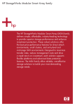
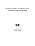
Front panel components
Item
Description
1
Bezel blank (bay for optional redundant controller)
2
Service port (for HP service technicians only)
3
Hot-plug HP StorageWorks Modular Smart Array 500
Generation 2 controller
12
HP StorageWorks MSA500 G2 Storage System User Guide
Item
Description
4
Controller display
5
Power On/Standby button
6
Enclosure LEDs
7
Hot-plug SCSI hard drive bays with blanks
Enclosure LEDs
Item
Description
Status
1
EMU heartbeat
Green flashing = Shared storage module is operating normally.
Green/Off = Shared storage module is not operating normally.
2
System power
Green = System power is On.
Off = System is in standby mode or power is removed from the
system.
3
Fault
Amber = Fault is detected in a subsystem.
Off = No faults are detected.
Component identification
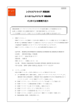
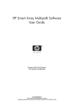
Rear panel components
Item
Description
1
Interconnect blanks (required for proper airflow)
2
Power supply/blower assemblies
3
AC power connectors
4
2-Port Shared Storage Module
13
14
HP StorageWorks MSA500 G2 Storage System User Guide
Power supply/blower assembly LEDs
The power supply/blower assembly LEDs have two functions:
•
Green—The power supply is receiving power, and the blower is operating
normally.
•
Off—No power is present; the power supply or the blower has failed.
Shared Storage Module with integrated
environmental monitoring unit
The storage system supports multipath two-node clustering and up to four-node
shared storage with Ultra320 SCSI I/O hardware. The storage system ships
standard with the 2-Port Shared Storage Module. A 4-Port Shared Storage
Module is available as an option.
Functions include:
•
Provides the interconnect function to the server nodes
•
Monitors the enclosure operation for:
– Temperature
– Power supplies
Component identification
15
– Blowers
– Drive presence
•
Detects and reports component changes in the enclosure (identifies hot-plug
addition and removal)
•
Controls drive and enclosure LEDs
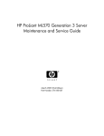
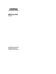
2-Port Shared Storage Module Components
Item
Description
Bus
1
SCSI port connector
A
2
SCSI port connector
B
16
HP StorageWorks MSA500 G2 Storage System User Guide
2-Port Shared Storage Module LEDs
Item
LED Description
Status
1
Power
Flashing green = Power on
Off = Power off
2
SCSI host port A
Flashing green = On/Activity
Off = Off
3
SCSI host port B
Flashing green = On/Activity
Off = Off
Component identification
4-Port Shared Storage Module Components
Item
Description
Bus
1
SCSI port connector A1
A
2
SCSI port connector A2
A
3
SCSI port connector B1
B
4
SCSI port connector B2
B
17
18
HP StorageWorks MSA500 G2 Storage System User Guide
4-Port Shared Storage Module LEDs
Item
LED Description
Status
1
Power
Flashing green = Power on
Off = Power off
2
3
SCSI host port A
connectors 1 and 2
Flashing green = On/Activity
SCSI host port B
connectors 1 and 2
Flashing green = On/Activity
Off = Off
Off = Off
Controller components
Controller Display (on page 19)
Controller LEDs (on page 20)
Battery-Backed Write Cache Enabler Overview (on page 21)
Component identification
Controller display
Each controller LCD provides informational and error messages.
Item
Description
1
Display
2
Left button
3
Up button
4
Right button
5
Down button
19
20
HP StorageWorks MSA500 G2 Storage System User Guide
Controller LEDs
Item
LED Description
Status
0-2
Busy status
Green = Controller is idle.
Off = Controller is operating at full capacity.
3-5
No function
—
6
Host port A notification
Green = Notify On Event command is
active.
Off = No Notify On Event command is
active.
7
Host port B notification
Green = Notify On Event command is
active.
Off = No Notify On Event command is
active.
8
Idle heartbeat
Controller is idle and functioning.
9
Active/Standby
Green = Controller is active.
Off = Controller is in standby.
10
DMA activity
Green = DMA transfers are active.
Off = No DMA transfers are active.
Component identification
Item
LED Description
Status
11
Logical I/O activity
Green = System is currently processing
logical requests from the host adapter.
21
Off = System is not processing any logical
requests.
12
SCSI bus 0 activity
Green = Outstanding requests exist on the
SCSI bus.
Off = No outstanding requests exist.
13
SCSI bus 1 activity
Green = Outstanding requests exist on the
SCSI bus.
Off = No outstanding requests exist.
14
Cache activity
Green = Cache activity is present.
Off = No cache activity is present.
Flashing green = Cache transfer is
pending.
15
Drive failure
Green = An array-configured drive has
failed.
Off = No drives have failed.
16
Active redundancy
Green = Controllers are operating with
redundancy.
Off = No redundancy exists.
17
Fault
Amber = Error message has been received
by the controller display.
Off = No error message has been received
or no error message is displayed currently.
Battery-Backed Write Cache Enabler Overview
The Battery-Backed Write Cache Enabler, also known as the battery module,
provides transportable data protection, increases overall controller performance,
and maintains any cached data for up to 72 hours. The NiMH batteries in the
battery module are continuously recharged through a trickle-charging process
whenever the system power is on. Under normal operating conditions, the battery
module lasts for 3 years before replacement is necessary.
22
HP StorageWorks MSA500 G2 Storage System User Guide
NOTE: The data protection and the time limit also apply if a power
outage occurs. When power is restored to the system, an initialization
process writes the preserved data to the hard drives.
To enable faster data access from disk storage, the battery module performs two
types of caching:
•
Posted-write caching—the controller writes user data in the cache memory
on the module rather than directly to the drives. Later, when the storage
system is idle, the controller writes the data to the drive array.
•
Read-ahead caching—the controller detects sequential array access, reads
ahead into the next sequence of data, and stores the data in the read-ahead
cache. Then, if the next read access is for the cached data, the controller
immediately loads the data into system memory, avoiding the latency of a
disk access.
SCSI IDs
Bay
SCSI ID
Bus Port
1
0
0
2
1
0
3
2
0
4
3
0
Component identification
Bay
SCSI ID
Bus Port
5
4
0
6
5
0
7
8
0
8
0
1
9
1
1
10
2
1
11
3
1
12
4
1
13
5
1
14
8
1
Hot-plug SCSI hard drive LEDs
Item
LED description
Status
1
Activity status
On = Drive activity
Flashing = High activity on the drive or drive
is being configured as part of an array.
Off = No drive activity
23
24
HP StorageWorks MSA500 G2 Storage System User Guide
Item
LED description
Status
2
Online status
On = Drive is part of an array and is
currently working.
Flashing = Drive is actively online.
Off = Drive is offline.
3
Fault status
On = Drive failure
Flashing = Fault-process activity
Off = No fault-process activity
Hot-plug SCSI hard drive LED combinations
Activity
LED (1)
Online
LED (2)
Fault LED Interpretation
(3)
On, off, or
flashing
On or off
Flashing
On, off, or
flashing
On
On or
flashing
Flashing
A predictive failure alert has been received for this drive.
Replace the drive as soon as possible.
Off
The drive is online and is configured as part of an array.
If the array is configured for fault tolerance and all other drives in the
array are online, and a predictive failure alert is received or a drive
capacity upgrade is in progress, you may replace the drive online.
Off
Do not remove the drive. Removing a drive may terminate the
current operation and cause data loss.
The drive is rebuilding or undergoing capacity expansion.
On
Off
Off
Do not remove the drive.
The drive is being accessed, but (1) it is not configured as part of an
array; (2) it is a replacement drive and rebuild has not yet started; or
(3) it is spinning up during the POST sequence.
Flashing
Flashing
Flashing
Do not remove the drive. Removing a drive may cause data loss
in non-fault-tolerant configurations.
Either (1) the drive is part of an array being selected by an array
configuration utility; (2) Drive Identification has been selected in
HP SIM; or (3) drive firmware is being updated.
Off
Off
On
The drive has failed and has been placed offline.
You may replace the drive.
Component identification
Activity
LED (1)
Online
LED (2)
Fault LED Interpretation
(3)
Off
Off
Off
25
Either (1) the drive is not configured as part of an array; (2) the drive
is configured as part of an array, but it is a replacement drive that is
not being accessed or being rebuilt yet; or (3) the drive is configured
as an online spare.
If the drive is connected to an array controller, you may replace the
drive online.
27
Operations
In this section
Power up the storage system ........................................................................................................27
Power down the storage system....................................................................................................28
Use the controller display .............................................................................................................28
Power up the storage system
Observe the following guidelines before powering up the storage system:
•
Be sure that all components are powered down.
•
Always install all components of the storage system and connect components
to the supported interconnect options.
•
Install hard drives in the storage system so the controller can identify and
configure them at power up.
CAUTION: You must power up the storage system before
powering up the servers. It may take up to 2 minutes for the storage
system to completely power up. Wait until the display provides the
Startup Complete message.
To power up the storage system:
1. Complete server hardware installation and cabling. Refer to the server
documentation.
2. Connect the SCSI cables and power cords to the storage system.
3. Press the Power On/Standby button.
Wait and observe the system power LED and controller display. When the
storage system goes from standby to full power, the system power LED
illuminates solid green, and the display provides a Startup Complete
message.
4. Power up the servers. Refer to the server documentation.
28
HP StorageWorks MSA500 G2 Storage System User Guide
Power down the storage system
WARNING: To reduce the risk of personal injury, electric
shock, or damage to the equipment, remove the power cord to
remove power from the storage system. The front panel Power
On/Standby button does not completely shut off system power.
Portions of the power supply and some internal circuitry remain
active until AC power is removed.
CAUTION: In systems that use external data storage, be sure
that the server is the first unit to be powered down and the last to be
powered back up. Taking this precaution ensures that the system does
not erroneously mark the drives as failed when the server is powered
up.
IMPORTANT: If installing a hot-plug device, it is not necessary to
power down the storage system.
1. Power down any attached servers. Refer to the server documentation.
2. Press the Power On/Standby button on the storage system. Wait for the
system power LED to go from green to off.
3. Disconnect the power cords.
The system is now without power.
Use the controller display
Each MSA500 G2 controller in the MSA500 G2 storage system contains an
integrated LCD. This module displays informational and error messages, shows
the current status of the module, and provides an interface for user input. The
storage system combines traditional POST messages issued by PCI-based array
controllers with runtime event notification messages for this new set of controller
display messages.
The display module consists of the following components:
•
A two-line, 20-column display text window
•
Four buttons
Operations
•
29
Two LEDs
Types of messages
The display module is capable of storing up to 100 messages. When the message
log is full, the system deletes the oldest message to make room for the most
recent one.
The types of messages include:
•
Error Messages—Error messages indicate a problem that may require user
action.
The Fault LED illuminates when you view an error message. It also
illuminates to indicate that an unviewed error message is in the queue and
was followed by other types of messages. When scrolling backward to view
all error messages, the LED illuminates only when an error message is in the
text display window.
•
Informational Messages—Informational messages provide feedback on
non-critical changes.
•
User Input Messages—User input messages indicate an issue that requires a
choice. The user can choose a selection before the end of a time-out period or
allow the controller to default to a standard choice. User input messages only
occur during system power up.
The Fault LED flashes when a user input message is in the text display
window and requires input. If the user does not provide input within the
time-out period, the message remains, but the LED stops flashing.
A complete list of error messages is available ("Display messages" on page 85).
Using the interface
•
Scrolling—To view older messages, scroll backward with the Up button
(indicated by the up arrow). To view newer messages, scroll forward with the
Down button (indicated by the down arrow).
The arrival of new messages supersedes the display of any previous
messages. When a new message arrives, the display ignores its previous
scrolling position and presents the new message.
30
HP StorageWorks MSA500 G2 Storage System User Guide
•
Selecting User Input Options—User input messages present the user with a
choice and define the options in the text display window. Select one of the
options by pushing the Left button (indicated by the left arrow) or the Right
button (indicated by the right arrow).
•
Deleting Messages—To delete a message, scroll to the message, then press
the Left and Right buttons simultaneously.
31
Setup
In this section
Rack planning resources...............................................................................................................31
Optimum environment..................................................................................................................32
Rack warnings ..............................................................................................................................35
Shipping contents .........................................................................................................................36
Rack mounting hardware kit contents ..........................................................................................37
Converting rails for round-hole racks...........................................................................................38
Installing a storage system into the rack.......................................................................................39
Installing hardware options ..........................................................................................................44
Installing servers...........................................................................................................................44
Choosing a configuration..............................................................................................................44
Cabling the storage system ...........................................................................................................46
Updating firmware........................................................................................................................48
Rack planning resources
The rack resource kit ships with all HP branded or Compaq branded 9000,
10000, and H9 series racks. A summary of the content of each resource follows:
•
Custom Builder is a web-based service for configuring one or many racks.
Rack configurations can be created using:
– A simple, guided interface
– Build-it-yourself mode
For more information, refer to the HP website
(http://www.hp.com/products/configurator).
•
The Installing Rack Products video provides a visual overview of operations
required for configuring a rack with rack-mountable components. It also
provides the following important configuration steps:
– Planning the site
– Installing rack servers and rack options
32
HP StorageWorks MSA500 G2 Storage System User Guide
– Cabling servers in a rack
– Coupling multiple racks
•
The Rack Products Documentation CD enables you to view, search, and print
documentation for HP and Compaq branded racks and rack options. It also
helps you set up and optimize a rack in a manner that best fits your
environment.
If you intend to deploy and configure multiple servers in a single rack, refer to
the white paper on high-density deployment on the HP website
(http://www.hp.com/products/servers/platforms).
Optimum environment
When installing the storage system in a rack, select a location that meets the
environmental standards described in this section.
Space and airflow requirements
To allow for servicing and adequate airflow, observe the following space and
airflow requirements when deciding where to install a rack:
•
Leave a minimum clearance of 63.5 cm (25 in) in front of the rack.
•
Leave a minimum clearance of 76.2 cm (30 in) behind the rack.
•
Leave a minimum clearance of 121.9 cm (48 in) from the back of the rack to
the back of another rack or row of racks.
HP storage systems draw in cool air through the front door and expel warm air
through the rear door. Therefore, the front and rear rack doors must be
adequately ventilated to allow ambient room air to enter the cabinet, and the rear
door must be adequately ventilated to allow the warm air to escape from the
cabinet.
CAUTION: To prevent improper cooling and damage to the
equipment, do not block the ventilation openings.
Setup
33
When a vertical space in the rack is not filled by a server or rack component, the
gaps between the components cause changes in airflow through the rack and
across the servers. Cover all gaps with blanking panels to maintain proper
airflow.
CAUTION: Always use blanking panels to fill empty vertical
spaces in the rack. This arrangement ensures proper airflow. Using a
rack without blanking panels results in improper cooling that can lead to
thermal damage.
The 9000 and 10000 Series racks provide proper server cooling from flowthrough perforations in the front and rear doors that provide 64 percent open area
for ventilation.
CAUTION: When using a Compaq branded 7000 Series rack,
you must install the high airflow rack door insert [P/N 327281-B21 (42U)
or P/N 157847-B21 (22U)] to provide proper front-to-back airflow and
cooling.
CAUTION: If a third-party rack is used, observe the following
additional requirements to ensure adequate airflow and to prevent
damage to the equipment:
•
Front and rear doors—If the 42U rack includes closing front and rear
doors, you must allow 5,350 sq cm (830 sq in) of holes evenly
distributed from top to bottom to permit adequate airflow (equivalent
to the required 64 percent open area for ventilation).
•
Side—The clearance between the installed rack component and the
side panels of the rack must be a minimum of 7 cm (2.75 in).
Temperature requirements
To ensure continued safe and reliable equipment operation, install or position the
storage system in a well-ventilated, climate-controlled environment.
The maximum TMRA for most storage system products is 35°C (95°F). The
temperature in the room where the rack is located must not exceed 35°C (95°F).
34
HP StorageWorks MSA500 G2 Storage System User Guide
CAUTION: To reduce the risk of damage to the equipment
when installing third-party options:
•
Do not permit optional equipment to impede airflow around the
storage system or to increase the internal rack temperature beyond
the maximum allowable limits.
•
Do not exceed the manufacturer’s TMRA.
Power requirements
Installation of this equipment must comply with local and regional electrical
regulations governing the installation of information technology equipment by
licensed electricians. This equipment is designed to operate in installations
covered by NFPA 70, 1999 Edition (National Electric Code) and NFPA-75, 1992
(code for Protection of Electronic Computer/Data Processing Equipment). For
electrical power ratings on options, refer to the product rating label or the user
documentation supplied with that option.
WARNING: To reduce the risk of personal injury, fire, or
damage to the equipment, do not overload the AC supply branch
circuit that provides power to the rack. Consult the electrical
authority having jurisdiction over wiring and installation
requirements of your facility.
CAUTION: Protect the storage system from power fluctuations
and temporary interruptions with a regulating UPS. This device protects
the hardware from damage caused by power surges and voltage spikes
and keeps the storage system in operation during a power failure.
When installing more than one storage system, you may need to use additional
power distribution devices to safely provide power to all devices. Observe the
following guidelines:
•
Balance the storage system power load between available AC supply branch
circuits.
•
Do not allow the overall system AC current load to exceed 80 percent of the
branch circuit AC current rating.
•
Do not use common power outlet strips for this equipment.
Setup
•
35
Provide a separate electrical circuit for the storage system.
Electrical grounding requirements
The storage system must be grounded properly for proper operation and safety.
In the United States, you must install the equipment in accordance with
NFPA 70, 1999 Edition (National Electric Code), Article 250, as well as any
local and regional building codes. In Canada, you must install the equipment in
accordance with Canadian Standards Association, CSA C22.1, Canadian
Electrical Code. In all other countries, you must install the equipment in
accordance with any regional or national electrical wiring codes, such as the
International Electrotechnical Commission (IEC) Code 364, parts 1 through 7.
Furthermore, you must be sure that all power distribution devices used in the
installation, such as branch wiring and receptacles, are listed or certified
grounding-type devices.
Because of the high ground-leakage currents associated with multiple storage
system connected to the same power source, HP recommends the use of a power
distribution unit (PDU) that is either permanently wired to the building’s branch
circuit or includes a nondetachable cord that is wired to an industrial-style plug.
NEMA locking-style plugs or those complying with IEC 60309 are considered
suitable for this purpose. Using common power outlet strips for the storage
system is not recommended.
Rack warnings
WARNING: To reduce the risk of personal injury or
damage to the equipment, be sure that:
36
HP StorageWorks MSA500 G2 Storage System User Guide
•
The leveling jacks are extended to the floor.
•
The full weight of the rack rests on the leveling jacks.
•
The stabilizing feet are attached to the rack if it is a single-rack
installation.
•
The racks are coupled together in multiple-rack installations.
•
Only one component is extended at a time. A rack may become
unstable if more than one component is extended for any
reason.
WARNING: To reduce the risk of personal injury or
equipment damage when unloading a rack:
•
At least two people are needed to safely unload the rack from
the pallet. An empty 42U rack can weigh as much as 115 kg
(253 lb), can stand more than 2.1 m (7 ft) tall, and may become
unstable when being moved on its casters.
•
Never stand in front of the rack when it is rolling down the ramp
from the pallet. Always handle the rack from both sides.
Shipping contents
Setup
Item
Description
1
MSA500 G2 storage system
2
Power cords (2)
3
Ethernet crossover cable
4
SCSI VHDCI cables (2)
5
4U rack template
6
Rack mounting hardware kit (not shown)
7
Smart Array 642 adapter (2, not shown)
8
Documentation set (not shown)
37
NOTE: The ethernet crossover cable is for Microsoft® and Linux
operating systems only.
In addition to these supplied items, you may need:
•
Application software diskettes
•
Options to be installed
•
No. 2 Phillips screwdriver
Rack mounting hardware kit contents
The rack mounting hardware kit provides the required components for quick
deployment in Compaq branded, HP branded, and most square- and round-hole
third-party racks. The adjustable feature of the rack rails enables installation in
racks with depths of 69.90 to 76.2 cm (27.52 to 30.00 in).
38
HP StorageWorks MSA500 G2 Storage System User Guide
If you are installing the MSA500 G2 storage system in an M-Series rack, contact
an authorized reseller to obtain an M-Series Rack Rail option kit.
Item
Description
1
Rack rail (left)
2
Rack rail (right)
3
Pins for round-hole rack conversion (8)
In addition to these supplied items, you may need a No. 2 Phillips screwdriver.
Converting rails for round-hole racks
The rack rails ship configured for square-hole racks. To convert the rack rails for
use in a round-hole rack:
1. Locate the bag of miscellaneous hardware that ships with the rack rails.
2. Locate the eight round-hole pins.
Setup
39
3. Use a No. 2 Phillips screwdriver to remove the standard pins from the front
and back ends of the rail.
4. Install four round-hole pins into the rail.
5. Repeat steps 3 and 4 for the second rail.
Installing a storage system into the rack
1. Mark the rack.
40
HP StorageWorks MSA500 G2 Storage System User Guide
CAUTION: Always plan the rack installation so that the
heaviest item is on the bottom of the rack. Install the heaviest item first,
and continue to populate the rack from the bottom to the top.
NOTE: Rack components are removed for clarity.
2. Secure the front end of the rails to the rack.
IMPORTANT: Do not remove the pins from the ends of the rack rails
unless you are converting the rails for use in round-hole racks. These
load-bearing pins are designed to fit through the holes without being
removed.
IMPORTANT: Be sure that the scissor-type locking latches engage the
rack fully when the pins extend through the holes marked with the
template.
Setup
NOTE: Identify the left (L) and right (R) rack rails by markings stamped
into the sheet metal.
3. Secure the back end of the rails to the rack.
IMPORTANT: Be sure that the scissor-type locking latches engage the
rack fully when the pins extend through the holes marked with the
template.
4. With one person on each side, lift the chassis to rail level and slide the
chassis on the mounting rails.
41
42
HP StorageWorks MSA500 G2 Storage System User Guide
WARNING: This storage system is very heavy. To reduce
the risk of personal injury or damage to the equipment:
•
Observe local occupational health and safety requirements and
guidelines for manual material handling.
•
Get help to lift and stabilize the product during installation or
removal, especially when the product is not fastened to the
rails. When the storage system weighs more than 22.5 kg
(50 lb), at least two people must lift the storage system into the
rack together. If the storage system is loaded into the rack
above chest level, a third person must assist in aligning the
rails while the other two support the storage system.
•
Use caution when installing the storage system in or removing
the storage system from the rack; it is unstable when not
fastened to the rails.
Setup
5. Secure the chassis to the rack.
6. Use the shipping bracket to secure the storage system for shipping:
IMPORTANT: Use of the shipping bracket is required only when the
rack is shipped with the MSA500 G2 storage system installed.
a. Loosen the thumbscrew on the shipping bracket.
b. Slide the shipping bracket forward until it engages the chassis.
c. Tighten the thumbscrew.
43
44
HP StorageWorks MSA500 G2 Storage System User Guide
Installing hardware options
Install any hardware options before initializing the storage system. For options
installation information, refer to the option documentation. For storage systemspecific information, refer to "Hardware Options Installation (on page 49)."
Installing servers
Install the servers in the rack directly above the storage system. Refer to the
server documentation.
Choosing a configuration
Cable procedures vary depending on the DAS, SSP, or multipath configuration.
Choose one of the following configurations.
Clustering configuration
Item
Description
1
MSA500 G2 storage system
2
VHDCI SCSI cables
Setup
Item
Description
3
Servers
4
Ethernet crossover cable
45
NOTE: The ethernet crossover cable is for Microsoft® and Linux
operating systems only.
Single-server configuration
Item
Description
1
MSA500 G2 storage system
2
VHDCI SCSI cable
3
Server
SSP hardware configurations
To configure the hardware for SSP, use SCSI cables to connect each server to the
2-Port or 4-Port Shared Storage Module installed in the storage system. Boot
volumes for individual servers can reside on server drives or storage system
drives.
46
HP StorageWorks MSA500 G2 Storage System User Guide
After choosing the configuration that best suits your needs, enable SSP with
ACU Version 7.10 or later. Locate ACU on the SmartStart CD. For instructions,
refer to the HP Array Configuration Utility User Guide on the Documentation
CD.
Other configurations
For four-node SSP configurations, refer to the documentation that ships with the
4-Port Shared Storage Module.
For multipath software configurations, refer to the HP Smart Array Multipath
Software User Guide that ships with that option.
For more information about these options, refer to the HP website
(http://www.hp.com/products/sharedstorage).
Cabling the storage system
After installing the storage system in a rack, connect the SCSI cables and power
cords to the rear panel.
SCSI cabling guidelines
Always be sure that the servers attached to the storage system are powered down
and power cords are disconnected before connecting SCSI cables.
IMPORTANT: Before installing the Smart Array Multipath software on a
server with a Microsoft® operating system, connect only one of the
SCSI cables from each server to the MSA500 G2 storage system.
Leave the second SCSI cable for the redundant path disconnected until
after the multipath software is installed.
For SSP cabling configurations, refer to "SSP Hardware Configurations (on page
63)."
Cluster cabling guidelines
To cable the cluster:
Setup
47
1. Install the server cable management solution. Refer to the server
documentation.
2. Connect the VHDCI SCSI cables to the storage system and servers.
For Microsoft® or Linux operating systems, connect the Ethernet crossover
cable between the servers. Use the RJ-45 connectors identified as NIC 2 on
each server.
3. Connect peripheral devices, such as a keyboard, mouse, or monitor.
IMPORTANT: HP recommends the use of a KVM switchbox. Refer to
the documentation that ships with the switchbox.
Power cords
The power cord should be approved for use in your country. The power cord
must be rated for the product and for the voltage and current marked on the
electrical ratings label of the product. The voltage and current rating for the cord
should be greater than the voltage and current rating marked on the product. In
2
addition, the diameter of the wire must be a minimum of 1.00 mm or 18 AWG,
your maximum length may be up to 3.66 m (12 ft).
WARNING: To reduce the risk of electric shock or damage
to the equipment:
•
Do not disable the power cord grounding plug. The grounding
plug is an important safety feature.
•
Plug the power cord into a grounded (earthed) electrical outlet
that is easily accessible at all times.
•
Unplug the power cord from the power supply to disconnect
power to the equipment.
•
Do not route the power cord where it can be walked on or
pinched by items placed against it. Pay particular attention to
the plug, electrical outlet, and the point where the cord extends
from the storage system.
To connect AC power cords:
1. Connect the power cords to the power supplies.
2. Connect the power cords to the AC power source.
48
HP StorageWorks MSA500 G2 Storage System User Guide
Updating firmware
After installing hardware and powering up the storage system for the first time,
be sure to verify that the storage system, controllers, HBAs, and drives have the
latest firmware. For firmware and software updates, refer to the HP website
(http://www.hp.com/products/serverstorage).
49
Hardware options installation
In this section
Firmware updates .........................................................................................................................49
Hot-plug SCSI hard drive options ................................................................................................49
4-Port Shared Storage Module option ..........................................................................................51
MSA500 G2 Controller option .....................................................................................................53
Cache module upgrade option ......................................................................................................55
MSA500 G2 high availability option ...........................................................................................58
Firmware updates
After installing hardware and powering up the storage system for the first time,
be sure to verify that the storage system, controllers, HBAs, and drives have the
latest firmware. For firmware and software updates, refer to the HP website
(http://www.hp.com/products/serverstorage).
Hot-plug SCSI hard drive options
When adding SCSI hard drives to the storage system, observe the following
general guidelines:
•
The system automatically sets all SCSI IDs.
•
If only one SCSI hard drive is used, install it in the bay with the lowest SCSI
ID number. ("SCSI IDs" on page 22)
•
Hot-plug hard drives must be 1-inch universal SCSI types.
•
Drives must be the same capacity to provide the greatest storage space
efficiency when drives are grouped together into the same drive array.
50
HP StorageWorks MSA500 G2 Storage System User Guide
Removing hard drive blanks
CAUTION: To prevent improper cooling and thermal damage,
do not operate the storage system unless all bays are populated with
either a component or a blank.
To remove the component:
To replace the blank, slide the blank into the bay until it locks into place.
Installing hot-plug SCSI hard drives
1. Remove the existing hard drive blank or hard drive from the drive bay
("Removing hard drive blanks" on page 50).
Hardware options installation
51
2. Install the hard drive.
3. Determine the status of the hard drive from the hot-plug hard drive LEDs
("Hot-plug SCSI hard drive LED combinations" on page 24, "Hot-plug SCSI
hard drive LEDs" on page 23).
4-Port Shared Storage Module option
The storage system ships standard with a 2-Port Shared Storage Module. To
upgrade the storage system and enable data transfer through four SCSI ports,
install the optional 4-Port Shared Storage Module.
Module installation requirements
To ensure that the HBAs can negotiate I/O paths with the MSA500 G2
controllers, always install the most recent firmware for the 4-Port Shared Storage
Module, the controller, and the HBAs:
•
For HBA firmware upgrade procedures, refer to the controller documentation
that ships with the hardware.
•
For controller and Shared Storage Module firmware upgrade procedures,
refer to the HP website (http://www.hp.com/support/proliantstorage).
52
HP StorageWorks MSA500 G2 Storage System User Guide
Installing the 4-port shared storage module
CAUTION: In systems that use external data storage, be sure
that the server is the first unit to be powered down and the last to be
powered back up. Taking this precaution ensures that the system does
not erroneously mark the drives as failed when the server is powered
up.
1. Power down the storage system (on page 28).
2. Disconnect the SCSI cabling connected to the 2-Port Shared Storage Module.
3. Remove the 2-Port Shared Storage Module.
Hardware options installation
53
4. Install the 4-Port Shared Storage Module.
MSA500 G2 Controller option
The HP StorageWorks Modular Smart Array 500 Generation 2 storage system
ships with one HP StorageWorks Modular Smart Array 500 Generation 2
controller. To provide redundancy and maximize uptime, install a second
MSA500 G2 controller.
Controller installation requirements
Observe the following guidelines:
•
If a controller has more than one cache DIMM, be sure that both DIMMs
have the same memory capacity.
•
Always upgrade the cache in both controllers in a storage system with
redundant controllers.
•
In a storage system with a redundant controller, be sure that both controllers
have the same number of DIMMs and that all DIMMs have the same
memory capacity.
54
HP StorageWorks MSA500 G2 Storage System User Guide
•
To configure an MSA500 G2 storage system for controller redundancy, both
controllers must execute the same version of firmware. If the controllers have
different firmware versions, the storage system responds as follows:
– In a hot-plug addition of the second controller, the storage system clones
the firmware version of the active controller onto the second controller.
After the second controller is reset, the controllers become redundant.
– In a non-hot-plug addition of the second controller, the storage system
examines the firmware versions of both controllers at power up and
clones the most recent version from one controller to the other controller.
Installing the MSA500 G2 Controller
CAUTION: To prevent improper cooling and thermal damage,
do not operate the storage system unless all bays are populated with
either a component or a blank.
1. Remove the bezel blank.
2. Open the locking latch on the redundant controller.
Hardware options installation
55
3. Install the controller.
4. Verify that the component is seated properly by observing its LEDs when the
storage system is at full power.
Cache module upgrade option
The MSA500 G2 controller ships with a 256-MB battery-backed cache module.
A second 256-MB battery-backed cache module is available as an option.
Cache module installation requirements
Observe the following guidelines:
•
Always power down the storage system when performing a cache upgrade.
•
If a controller has more than one cache DIMM, be sure that both DIMMs
have the same memory capacity.
•
Always upgrade the cache in both controllers in a storage system with
redundant controllers.
•
In a storage system with a redundant controller, be sure that both controllers
have the same number of DIMMs and that all DIMMs have the same
memory capacity.
56
HP StorageWorks MSA500 G2 Storage System User Guide
Installing the cache module upgrade
1. Power down the storage system (on page 28).
2. Remove the controller.
3. Remove the existing cache module.
Hardware options installation
57
4. Install the new cache module.
5. Install the controller.
6. Power up the storage system (on page 27).
7. Verify that the component is seated properly by observing its LEDs when the
storage system is at full power.
58
HP StorageWorks MSA500 G2 Storage System User Guide
MSA500 G2 high availability option
The HP StorageWorks Modular Smart Array 500 Generation 2 storage system
high availability kit transforms the standard shipping MSA500 G2 storage
system into a redundant hardware solution that supports:
•
Two-node clustering
•
Array controller failover capability
•
Up to four-node DAS with Ultra320 SCSI I/O
The kit contains the following hardware and software components:
•
4-Port Shared Storage Module
•
HP Smart Array Multipath Software CD
•
Two Smart Array 642 adapters
•
An HP StorageWorks Modular Smart Array 500 Generation 2 controller
•
Two 1.8-m (6-ft) VHDCI SCSI cables
•
Assorted documentation
For instructions and further information about this option, refer to the HP website
(http://www.hp.com/products/sharedstorage).
59
Configuration and utilities
In this section
Server utilities...............................................................................................................................59
ROM functions and utilities .........................................................................................................61
Selective Storage Presentation......................................................................................................63
Array Configuration Utility ..........................................................................................................64
Array Diagnostic Utility ...............................................................................................................67
NetWare Online Array Configuration Utility (CPQONLIN) .......................................................68
Server utilities
HP utilities provide reporting functions that enable event-focused management
and diagnostics. To install and run these utilities, refer to the server
documentation.
HP Insight Diagnostics
HP Insight Diagnostics is a proactive server management tool, available in both
offline and online versions, that provides diagnostics and troubleshooting
capabilities to assist IT administrators who verify server installations,
troubleshoot problems, and perform repair validation.
HP Insight Diagnostics Offline Edition performs various in-depth system and
component testing while the OS is not running. To run this utility, launch the
SmartStart CD.
HP Insight Diagnostics Online Edition is a web-based application that captures
system configuration and other related data needed for effective server
management. Available in Microsoft® Windows® and Linux versions, the utility
helps to ensure proper system operation.
For more information or to download the utility, refer to the HP website
(http://www.hp.com/servers/diags).
60
HP StorageWorks MSA500 G2 Storage System User Guide
HP Systems Insight Manager
HP SIM is a web-based application that allows system administrators to
accomplish normal administrative tasks from any remote location, using a web
browser. HP SIM provides device management capabilities that consolidate and
integrate management data from HP and third-party devices.
IMPORTANT: You must install and use HP SIM to benefit from the PreFailure Warranty for processors, hard drives, and memory modules.
For additional information, refer to the Management CD in the HP ProLiant
Essentials Foundation Pack or the HP SIM website
(http://www.hp.com/go/hpsim).
Management Agents
Management Agents provide the information to enable fault, performance, and
configuration management. The agents allow easy manageability of the server
through HP SIM software, and third-party SNMP management platforms.
Management Agents are installed with every SmartStart assisted installation or
can be installed through the HP PSP. The Systems Management homepage
provides status and direct access to in-depth subsystem information by accessing
data reported through the Management Agents. For additional information, refer
to the Management CD in the HP ProLiant Essentials Foundation Pack or the HP
website (http://www.hp.com/servers/manage).
Survey Utility
Survey Utility, a feature within Insight Diagnostics, gathers critical hardware and
software information on ProLiant servers.
This utility supports operating systems that may not be supported by the server.
For operating systems supported by the server, refer to the HP website
(http://www.hp.com/go/supportos).
If a significant change occurs between data-gathering intervals, the Survey
Utility marks the previous information and overwrites the Survey text files to
reflect the latest changes in the configuration.
Configuration and utilities
61
Survey Utility is installed with every SmartStart-assisted installation or can be
installed through the HP PSP.
ROM functions and utilities
Each MSA500 G2 controller has a ROM that contains the controller firmware.
Smart Components for ROM Flash
To update the firmware on the server, controller, or hard drives, use Smart
Components. These components are available on the Firmware Maintenance CD.
A more recent version of a particular server or controller component might be
available on the support page of the HP website (http://www.hp.com/support).
Components for controller and hard drive firmware updates are also available
from the software and drivers page for storage products
(http://www.hp.com/support/proliantstorage).
1. Find the most recent version of the component that you require. Components
for controller firmware updates are available in offline and online formats.
2. Follow the instructions for installing the component on the server. These
instructions are given with the CD and are provided on the same Web page
as the component.
Follow the additional instructions that describe how to use the component to
flash the ROM. These instructions are provided with each component.
Recovery ROM
The Recovery ROM feature stores two complete firmware images in the ROM:
one active image and one backup image. When the controller is powering up, it
checks both firmware images to be sure they are valid. If either image is invalid,
the system overwrites the invalid image with the valid image.
This process, commonly called auto-flashing, is performed automatically by the
controller and does not require any user intervention. The controller display
provides messages for the status of this process.
62
HP StorageWorks MSA500 G2 Storage System User Guide
Controller firmware auto cloning
In a redundant controller configuration, both controllers must execute the same
version of firmware. During power up (or when a redundant controller is
installed as a hot-plug procedure), the storage system compares the controller
firmware versions. If the versions differ, the controller displays a user input
message seeking to initiate Controller Firmware Auto Cloning.
If 60 seconds elapse with no user input, one of the following actions occurs:
•
In a non-hot-plug environment, the controller with the most recent firmware
disables the controller with the older firmware and continues the power-up
sequence. This method prevents automatic loss of a previous version of
firmware.
•
In a hot-plug environment, cloning begins automatically, and the storage
system overwrites one firmware version with the other version.
When the cloning is complete, the storage system resets the modified controller.
After the modified controller powers up, the controllers begin operating in
redundant mode.
The storage system clones firmware based on the following criteria:
•
Non-Hot-Plug Cloning—If the storage system powers up with both
controllers installed, the storage system clones the most recent firmware
version from either controller.
•
Hot-Plug Cloning—If the storage system is operating and an optional
redundant controller is installed, the storage system clones the firmware
version from the primary controller, regardless of which firmware version is
more recent. This cloning method ensures that all host-initiated I/O remains
uninterrupted during storage system operation.
•
Incompatible Version Cloning—If a specific version of firmware is
incompatible with certain hardware revisions of a controller, the storage
system displays the user input message seeking to initiate Controller
Firmware Auto Cloning and clones the most recent firmware version that is
compatible with both controllers.
Configuration and utilities
63
IMPORTANT: During incompatible version cloning, the storage system
does not reset the updated controller if the controller is operating and
processing I/O. In this case, the storage system does not enter
redundant mode and provides an informational message on the
controller display. To configure redundancy, cycle the storage system
power.
Selective Storage Presentation
SSP is a controller firmware feature that enables the administrator to control
access from hosts to logical drives on the MSA500 G2 storage system. The
administrator selects which server host or hosts can access the stored data,
restricting access as needed to assure data integrity and security.
Each logical drive on the HP StorageWorks Modular Smart Array 500
Generation 2 controller has an access control list that contains the IDs of the
server host adapters that have access to the drive. If a server attempts to send
commands to a logical drive without access authority, the controller rejects the
command.
The configuration utility maps the IDs of server host adapters to connection
names and sets up access control lists for logical drives based on the adapter IDs.
SSP hardware configurations
To configure the hardware for SSP, use SCSI cables to connect each server to the
2-Port or 4-Port Shared Storage Module installed in the storage system. Boot
volumes for individual servers can reside on server drives or storage system
drives.
Enabling SSP
After choosing the configuration that best suits your needs, enable SSP with
ACU Version 7.10 or later. Locate ACU on the SmartStart CD. For instructions,
refer to the HP Array Configuration Utility User Guide on the Documentation
CD.
64
HP StorageWorks MSA500 G2 Storage System User Guide
Array Configuration Utility
ACU is a browser-based utility with the following features:
•
Runs as a local application or remote service
•
Supports online array capacity expansion, logical drive extension,
assignment of online spares, and RAID or stripe size migration
•
Suggests the optimum configuration for an unconfigured system
•
Provides different operating modes, enabling faster configuration or greater
control over the configuration options
•
Remains available any time that the server is on
•
Displays on-screen tips for individual steps of a configuration procedure
For optimum performance, the minimum display settings are 800 × 600
resolution and 256 colors. Servers running Microsoft® operating systems require
Internet Explorer 5.5 (with Service Pack 1) or later. For Linux servers, refer to
the README.TXT file for additional browser and support information.
For more information, refer to the HP Array Configuration Utility User Guide on
the Documentation CD or the HP website (http://www.hp.com).
Moving drives and arrays
You can move drives to other ID positions on the same array controller. You can
also move a complete array from one controller to another, even if the controllers
are on different storage systems.
Before you move drives, the following conditions must be met:
•
The move will not result in more than 14 physical drives per controller
channel.
•
No controller will be configured with more than 32 logical volumes.
•
The array has no failed or missing drives.
•
The array is in its original configuration.
Configuration and utilities
65
•
The controller is not reading from or writing to any of the spare drives in the
array.
•
The controller is not running capacity expansion, capacity extension, or
RAID or stripe size migration.
•
The controller is using the latest firmware version (recommended).
If you want to move an array to another controller, you must also consider the
following additional limitations:
•
All drives in the array must be moved at the same time.
•
Drive positions of the destination controller must match original drive
positions.
When all the conditions have been met:
1. Back up all data before removing any drives or changing configuration. This
step is required if you are moving data-containing drives from a controller
that does not have a battery-backed cache.
2. Power down the storage system (on page 28).
3. If you are moving an array from a controller that contains a RAID ADG
logical volume to a controller that does not support RAID ADG:
a. Remove or disconnect the drives that contain the RAID ADG logical
volume.
b. Reboot the storage system.
c. Open ACU and navigate to the controller that contained the RAID ADG
volume.
ACU displays the missing RAID ADG volume using a different icon to
indicate that the volume is unavailable.
d. Delete the RAID ADG volume.
e. Accept the configuration change, and then close ACU.
f.
Power down the storage system (on page 28).
4. Move the drives.
5. Power up the storage system (on page 27).
66
HP StorageWorks MSA500 G2 Storage System User Guide
– If an 86 controller display message appears, drive positions were changed
successfully and the configuration was updated.
– If a 121 controller display (no volumes) message appears, power down
the system immediately to avoid data loss, and return the drives to their
original positions.
6. Check the new drive configuration by running ORCA or ACU.
Expanding and extending capacity
You can add hard drives to a system at any time, as long as you do not exceed the
maximum number of drives that the controller supports. You can then either
build a new array from the added drives or use the extra storage capacity to
expand the capacity of an existing array.
To perform an array capacity expansion, use ACU. If the system is using hotpluggable drives, you can expand array capacity without shutting down the
operating system (that is, with the server online) if ACU is running in the same
environment as the normal server applications. (For more information, refer to
the HP Array Configuration Utility User Guide.)
Configuration and utilities
67
The expansion process is illustrated in the following figure, in which the original
array (containing data) is shown with a dashed border and the newly added drives
(containing no data) are shown unshaded. The array controller adds the new
drives to the array and redistributes the original logical drives over the enlarged
array one logical drive at a time. This process liberates some storage capacity on
each of the physical drives in the array. During this procedure, the logical drives
each keep the same fault-tolerance method in the enlarged array that they had in
the smaller array.
When the expansion process has finished, you can use the liberated storage
capacity on the enlarged array to create new logical drives. Alternatively, you
can enlarge one of the original logical drives. This latter process is called logical
drive capacity extension and is also carried out using ACU.
Array Diagnostic Utility
ADU is tool that collects information about array controllers and generates a list
of detected problems. ADU can be accessed from the SmartStart CD or
downloaded from the HP website (http://www.hp.com).
68
HP StorageWorks MSA500 G2 Storage System User Guide
NetWare Online Array Configuration Utility
(CPQONLIN)
The NetWare Online Array Configuration Utility, also called CPQONLIN, is an
NLM for configuring drive arrays without shutting down the storage system.
CPQONLIN also provides information about the status of drives attached to the
MSA500 G2 controller. It indicates drive failure, expansion, or waiting for
expansion or rebuild (queued). Before loading CPQONLIN.NLM, you must load
the appropriate device drivers: CPQRAID.HAM and CPQSHD.CDM.
CPQONLIN.NLM is located in the ProLiant Support Pack found on the
SmartStart CD and it is available on the support software CD that ships with the
storage system.
IMPORTANT: CPQONLIN supports SSP configurations; however, you
can also use ACU 7.10 (or later) offline to enable SSP configurations in
a NetWare environment.
Using auto-configuration
If no logical drives are configured, a CPQONLIN auto-configuration wizard
appears and prompts you to select fault-tolerance information. CPQONLIN then
configures arrays optimally for the selected fault tolerance.
Creating a custom configuration
Custom configuration enables you to create arrays and assign fault tolerance one
array at a time. To custom configure an array:
1. Go to the Main Configuration View screen.
2. Highlight the controller, array, or logical drives to be configured.
3. Make a selection from the Options menu located on the right side of the
screen.
4. Use online help for completing configurations. The following sections
discuss CPQONLIN functions.
Configuration and utilities
69
Customizing the chassis name
The Chassis Name field is available for a user-defined, customized name that
helps define the connection between the server HBA and the storage system
controller. This field prevents the user from relying entirely on the adapter ID of
the host controller for identification purposes.
Enabling chassis identification
The Identify Chassis field enables the user to set the Chassis Blink Status. When
enabled through the server HBA, CPQONLIN directs the storage system
controller to start flashing the hard drives LEDs in the storage system chassis.
When the setting is disabled, the hard drive LEDs stop flashing.
Setting drive rebuild, expand priority, and accelerator ratio
1. Go to the Main Configuration View screen.
2. Highlight the controller.
3. Select the Controller Settings option below Controller Options. The
Controller Settings screen appears.
Drive rebuild
Drive rebuild occurs after a physical drive fails and is replaced. Only logical
drives configured for fault tolerance (RAID 1, RAID 5, ADG) on the array with
the failed physical drive will rebuild.
Priority settings
To set the drive rebuild priority:
1. Highlight the MSA500 G2 controller.
2. Select the controller settings:
– If you choose low priority for drive rebuild, drive rebuilding occurs when
I/O to the drive is inactive.
– If you choose high priority, drive rebuilding occurs faster, at the expense
of normal I/O operations.
70
HP StorageWorks MSA500 G2 Storage System User Guide
Accelerator ratio
The MSA500 G2 controller has an onboard cache called an Array Accelerator,
which performs both write-posting and read-ahead caching. The setting in
CPQONLIN determines the amount of memory allocated to the read and write
caches.
For example, if the Accelerator Ratio is set to Read 75%:Write 25%, 75% of
Array Accelerator cache is dedicated to read-ahead cache and 25% is dedicated
to the write-posting cache. This option can be modified from the Controller
Settings menu.
Expanding an array
During an expand, performance may be slightly degraded. In most cases,
however, any potential degradation is offset by the addition of physical drives.
Some tips for expanding include:
•
Perform the expand process during periods of low server use. If you must
expand during peak periods, CPQONLIN enables you to set the priority of
the expand. Setting the priority to LOW affects performance the least, but it
takes longer for the new space to become available.
•
When expanding, always add drives with a capacity equal to or greater than
the capacity of the smallest drive in the array. Adding larger drives wastes
space because only the space that is equal to the smallest drive size can be
used.
Adding or configuring spare drives
When adding a spare drive to an array, an unassigned drive must exist or a drive
already assigned as a spare must exist on another array. You can assign a single
spare to any number of arrays or assign separate spares.
When you select Assign Spare Drive, only drives that qualify appear (for
example, only those spares that are large enough appear). If drives that you
expect to see do not appear, switch to the physical drive view (Tab key), and
check the size of the drives. The capacity of the spare must be equal to or greater
than the capacity of the smallest drive in the array.
Configuration and utilities
71
Migrating RAID level and stripe size online
Using CPQONLIN, you can modify both the RAID level and stripe size of an
existing logical drive while online. To migrate a drive:
1. Select the drive setting option under the logical drive menu for the drive you
intend to modify.
2. Select the new RAID level and/or stripe size from the choices presented. If
the new settings are valid, the migration begins when you save the changes.
73
Cluster installation and configuration
In this section
Cluster hardware installation ........................................................................................................73
Cluster configuration ....................................................................................................................74
Cluster hardware installation
To install the cluster:
1. Select an installation site that meets the optimum environment requirements.
Refer to the server documentation.
2. Install the storage system into the rack.
3. Install the servers into the rack, directly above the storage system. Refer to
the server documentation.
4. Install options:
– To install storage system options, refer to "Hardware Options Installation
(on page 49)."
– To install server options, refer to the server documentation or the
documentation that ships with the option.
5. Cable the system:
a. Install the server cable management solution. Refer to the server
documentation.
b. Connect the VHDCI SCSI cables to the storage system and servers.
For Microsoft® or Linux operating systems, connect the Ethernet
crossover cable between the servers. Use the RJ-45 connectors identified
as NIC 2 on each server.
c. Connect peripheral devices, such as a keyboard, mouse, or monitor.
IMPORTANT: HP recommends the use of a KVM switchbox. Refer to
the documentation that ships with the switchbox.
74
HP StorageWorks MSA500 G2 Storage System User Guide
6. Connect the power cords.
IMPORTANT: HP recommends the use of a UPS. Contact the nearest
authorized reseller.
Cluster configuration
Depending on the operating system, use the appropriate installation instructions
provided on the HP website
(http://www.hp.com/servers/proliant/highavailability).
The ProLiant high availability website has a link to technical white papers that
cover a variety of topics for each ProLiant cluster product. Topics include:
•
Installation checklists
•
Best practices
•
Deployment
•
Migration checklists
•
Applications
•
General cluster information
75
Troubleshooting
In this section
When the storage system does not start........................................................................................75
Diagnostic steps............................................................................................................................76
Recognizing hard drive failure .....................................................................................................78
Factors to consider before replacing hard drives..........................................................................81
Automatic data recovery (rebuild)................................................................................................82
Drive failure in a NetWare environment ......................................................................................84
Display messages..........................................................................................................................85
When the storage system does not start
If the storage system does not start:
1. Be sure that the attached server and monitor are working properly.
2. Be sure that the storage system is plugged into working outlets.
3. Be sure that the power source is working properly:
– Check the status using the system power LED on the front panel.
– Be sure that the Power On/Standby button was pressed firmly.
4. Be sure that the power supplies are working properly:
Check the status using the power supply LEDs ("Power supply/blower
assembly LEDs" on page 14).
5. Restart the system.
IMPORTANT: If the system does not restart, proceed to "Diagnostic
Steps (on page 76)."
6. Check the storage system for the following normal power-up sequence to be
sure that the system meets the minimal hardware requirements and is
powered up during normal operations:
a. The front panel power LED turns from off (standby/off) to on (solid
green).
76
HP StorageWorks MSA500 G2 Storage System User Guide
b. The blowers start up.
c. The 2-Port or 4-Port Shared Storage Module LED flashes green.
7. The controller display provides a Startup Complete message.
Diagnostic steps
If the storage system does not power up or powers up but does not complete
POST, answer the questions in the following table to determine appropriate
actions based on the symptoms observed.
According to the answers you give, you are directed to the appropriate table. That
table outlines possible reasons for the problem, options available to assist in
diagnosis, possible solutions, and references to other sources of information.
Question
Action
Question 1: Are the power
supply/blower assembly LEDs
green?
If yes, continue to question 2.
Question 2: Is the system power
LED green?
If yes, continue to question 3.
Question 3: Is the controller display
providing messages?
If yes, use the messages for further
diagnosis.
If no, refer to "Are the Power
Supply/Blower Assembly LEDs green?
(on page 77)."
If no, refer to "Is the System Power
LED Green? (on page 77)."
If no, refer to "Is the Controller Display
Providing Messages? (on page 78)."
Troubleshooting
Are the power supply/blower assembly LEDs green?
Answer
Possible Reasons
Possible Solutions
No
The power cords are not connected or AC
power is not available.
Be sure that the power cord is connected to
the power supply.
The power supply may not be inserted
properly, it may have a damaged
connector, or it may have failed.
Be sure that the power supply is undamaged
and is fully seated.
The system backplane may need to be
replaced.
Yes
—
Be sure that all pins on connectors and
components are straight.
Contact an authorized service provider for
assistance.
If the system power LED is off, do the
following:
1.
Press the Power On/Standby button.
2.
Refer to Is the System Power LED
Green? (on page 77).
Is the system power LED green?
Answer
Possible Reasons
Possible Solutions
No
The Power On/Standby button has not
been pressed firmly.
Firmly press the Power On/Standby button.
The power supply may not be inserted
properly, it may have a damaged
connector, or it may have failed.
Yes
Be sure that the power supply is undamaged
and is fully seated.
Be sure that all pins on connectors and
components are straight.
The system may have experienced a
short.
Be sure that all components are fully seated.
Controller firmware may be corrupted.
Flash the controller firmware ("Smart
Components for ROM Flash" on page 61).
The system backplane and/or power
button/LED assembly may need to be
replaced.
Contact an authorized service provider for
assistance.
—
If the system power LED is green, refer to "Is
the Controller Display Providing Messages?
(on page 78)."
77
78
HP StorageWorks MSA500 G2 Storage System User Guide
Is the controller display providing messages?
Answer
Possible Reasons
Possible Solutions
No
The controller may not be inserted
properly, it may have a damaged
connector, or it may have failed.
Be sure that the controller is undamaged and
is fully seated.
Be sure that all pins on connectors and
components are straight.
Contact an authorized service provider for
assistance.
When the controller display is working
properly, refer to the Yes response below.
Yes
—
Display messages are available for
diagnosis. Determine the next action by
observing the messages ("Display
messages" on page 85).
Recognizing hard drive failure
In an HP storage system, a steadily glowing Fault LED indicates that that drive
has failed. When a drive is configured as part of an array and attached to a
powered up controller, the status of the drive can be determined from the
illumination pattern of the controller LEDs (on page 20).
Other means by which hard drive failure is revealed are:
•
The amber LED on the front of a storage system illuminates if failed drives
are inside. (However, this LED also illuminates when other problems occur,
such as when a blower fails, a redundant power supply fails, or the system
overheats.)
•
A controller display message lists failed drives whenever the system is
restarted, as long as the controller detects at least one functional drive.
•
ACU represents failed drives with a distinctive icon.
•
HP SIM can detect failed drives remotely across a network. (For more
information about HP SIM, refer to the documentation on the Management
CD.)
Troubleshooting
•
ADU lists all failed drives.
•
CPQONLIN identifies failed drives in a NetWare environment.
79
For additional information about diagnosing hard drive problems, refer to the HP
ProLiant Servers Troubleshooting Guide.
CAUTION: Sometimes, a drive that has previously been failed
by the controller may seem to be operational after the system is powercycled or (for a hot-pluggable drive) after the drive has been removed
and reinserted. However, continued use of such marginal drives may
eventually result in data loss. Replace the marginal drive as soon as
possible.
Effects of a hard drive failure
When a hard drive fails, all logical drives that are in the same array are affected.
Each logical drive in an array may be using a different fault-tolerance method, so
each logical drive can be affected differently.
•
RAID 0 configurations cannot tolerate drive failure. If any physical drive in
the array fails, all non-fault-tolerant (RAID 0) logical drives in the same
array will also fail.
•
RAID 1+0 configurations can tolerate multiple drive failures as long as no
failed drives are mirrored to one another.
•
RAID 5 configurations can tolerate one drive failure.
•
RAID ADG configurations can tolerate simultaneous failure of two drives.
Compromised fault tolerance
If more hard drives fail than the fault-tolerance method allows, fault tolerance is
compromised, and the logical drive fails. In this case, all requests from the
operating system are rejected with unrecoverable errors. You are likely to lose
data, although it can sometimes be recovered.
80
HP StorageWorks MSA500 G2 Storage System User Guide
One example of a situation in which compromised fault tolerance may occur is
when a drive in an array fails while another drive in the array is being rebuilt. If
the array has no online spare, any logical drives in this array that are configured
with RAID 5 fault tolerance will fail.
Compromised fault tolerance can also be caused by non-drive problems, such as
a faulty cable or temporary power loss to a storage system. In such cases, you do
not need to replace the physical drives. However, you may still have lost data,
especially if the system was busy at the time that the problem occurred.
Recovering from compromised fault tolerance
If fault tolerance is compromised, inserting replacement drives does not improve
the condition of the logical volume. Instead, if the screen displays unrecoverable
error messages, perform the following procedure to recover data:
1. Check for loose, dirty, broken, or bent cabling and connectors on all devices.
2. Power down the storage system (on page 28).
3. Power up the storage system (on page 27).
In some cases, a marginal drive will work again for long enough to enable
you to make copies of important files.
4. If an 02 or 04 controller display message is displayed, press the Right button
to re-enable the logical volumes. Remember that data loss has probably
occurred and any data on the logical volume is suspect.
5. Make copies of important data, if possible.
6. Replace any failed drives.
7. After you have replaced the failed drives, fault tolerance may again be
compromised. If so, cycle the power again, and if the 02 or 04 controller
display message is displayed, press the Right button to re-enable the logical
volumes.
Troubleshooting
81
Factors to consider before replacing hard drives
•
In systems that use external data storage, be sure that the server is the first
unit to be powered down and the last to be powered back up. Taking this
precaution ensures that the system does not erroneously mark the drives as
failed when the server is powered up.
•
If you set the SCSI ID jumpers manually:
– Check the ID value of the removed drive to be sure that it corresponds to
the ID of the drive marked as failed.
– Set the same ID value on the replacement drive to prevent SCSI ID
conflicts.
Before replacing a degraded drive:
•
Open HP SIM and inspect the Error Counter window for each physical drive
in the same array to confirm that no other drives have any errors. (For details,
refer to the HP SIM documentation on the Management CD.)
•
Be sure that the array has a current, valid backup.
•
Use replacement drives that have a capacity at least as great as that of the
smallest drive in the array. The controller immediately fails drives that have
insufficient capacity.
To minimize the likelihood of fatal system errors, take these precautions when
removing failed drives:
•
Do not remove a degraded drive if any other drive in the array is offline (the
Online LED is off). In this situation, no other drive in the array can be
removed without data loss.
Exceptions:
– When RAID 1+0 is used, drives are mirrored in pairs. Several drives can
be in a failed condition simultaneously (and they can all be replaced
simultaneously) without data loss, as long as no two failed drives belong
to the same mirrored pair.
– When RAID ADG is used, two drives can fail simultaneously (and be
replaced simultaneously) without data loss.
– If the offline drive is a spare, the degraded drive can be replaced.
82
HP StorageWorks MSA500 G2 Storage System User Guide
•
Do not remove a second drive from an array until the first failed or missing
drive has been replaced and the rebuild process is complete. (The rebuild is
complete when the Online LED on the front of the drive stops blinking.)
These cases are the exceptions:
– In RAID ADG configurations, any two drives in the array can be replaced
simultaneously.
– In RAID 1+0 configurations, any drives that are not mirrored to other
removed or failed drives can be simultaneously replaced offline without
data loss.
Automatic data recovery (rebuild)
When you replace a hard drive in an array, the controller uses the fault-tolerance
information on the remaining drives in the array to reconstruct the missing data
(the data that was originally on the replaced drive) and write it to the replacement
drive. This process is called automatic data recovery, or rebuild. If fault tolerance
is compromised, this data cannot be reconstructed and is likely to be permanently
lost.
If another drive in the array fails while fault tolerance is unavailable during
rebuild, a fatal system error may occur, and all data on the array is then lost. In
exceptional cases, however, failure of another drive need not lead to a fatal
system error. These exceptions include:
•
Failure after activation of a spare drive
•
Failure of a drive that is not mirrored to any other failed drives (in a RAID
1+0 configuration)
•
Failure of a second drive in a RAID ADG configuration
Time required for a rebuild
The time required for a rebuild varies considerably, depending on several factors:
•
The priority that the rebuild is given over normal I/O operations (you can
change the priority setting by using ACU)
•
The amount of I/O activity during the rebuild operation
Troubleshooting
•
The rotational speed of the hard drives
•
The availability of drive cache
•
The brand, model, and age of the drives
•
The amount of unused capacity on the drives
•
The number of drives in the array (for RAID 5 and RAID ADG)
83
Allow approximately 15 minutes per gigabyte for the rebuild process to be
completed. This figure is conservative, and newer drive models usually require
less time to rebuild.
System performance is affected during the rebuild, and the system is unprotected
against further drive failure until the rebuild has finished. Therefore, replace
drives during periods of low activity when possible.
CAUTION: If the Online LED of the replacement drive stops
blinking and the amber Fault LED glows, or if other drive LEDs in the
array go out, the replacement drive has failed and is producing
unrecoverable disk errors. Remove and replace the failed replacement
drive.
When automatic data recovery has finished, the Online LED of the replacement
drive stops blinking and begins to glow steadily.
Failure of another drive during rebuild
If a non-correctable read error occurs on another physical drive in the array
during the rebuild process, the Online LED of the replacement drive stops
blinking and the rebuild abnormally terminates.
If this situation occurs, reboot the server. The system may temporarily become
operational long enough to allow recovery of unsaved data. In any case, locate
the faulty drive, replace it, and restore data from backup.
84
HP StorageWorks MSA500 G2 Storage System User Guide
Drive failure in a NetWare environment
Use CPQONLIN to identify and monitor drive failure status in a NetWare
environment.
Failed drives or interim recovery mode
If a drive fails and hardware fault tolerance is enabled, operation continues. Do
the following:
1. Replace the drive as soon as possible.
2. Select a logical drive.
3. Press the F3 key to monitor to the status of drive recovery.
Drive status messages include:
•
Interim Recovery: The logical drive is operating, but a failed drive has not
been replaced. Replace the drive as soon as possible.
•
Ready for Recovery: The logical drives are queued for recovery. This status
is displayed when another logical drive is already rebuilding or expanding.
•
Rebuilding: The array is operating and rebuilding a replacement drive or an
online spare, if one was assigned.
•
Logical Drive Failed: If you have one or more logical drives that are not
protected by fault tolerance in an array, the data on these logical drives will
be lost. ACU shows the logical drives as FAILED. After drive replacement,
any fault-tolerant logical drives rebuild. The logical drives that were not
protected (FAILED) become available for data (the devices are reactivated
automatically). If you have a backup of the data, restore the data now.
If you do not replace the failed drive, the only option, using ACU, is to delete
logical drives. Do not delete logical drives that contain valid data. Doing so
results in data loss.
NOTE: A failed status can occur on drives protected by fault tolerance
if two or more physical drives fail concurrently.
Troubleshooting
85
Some status messages are available without pressing the F3 key. For example, on
the Main menu, the FAILED status appears next to the logical drive that has
failed. EXPANDING and REBUILDING appear next to the array in which the
activity is occurring.
Handling disk drive failures
If the MSA500 G2 controller was configured with hardware fault tolerance,
complete the following steps after a disk drive failure:
1. Determine which physical drive failed. On hot-plug drives, an amber drive
failure LED illuminates.
2. If the unit containing the failed drive does not support hot-plug drives,
perform a normal shutdown.
3. Remove the failed drive and replace it with a drive that is of the same
capacity. For hot-plug drives, after you secure the drive in the bay, the LEDs
on the drive each flash once in an alternating pattern to indicate a successful
connection. The online LED flashes, indicating that the controller recognized
the drive replacement and began the recovery process.
4. Power up the server, if applicable.
5. The MSA500 G2 controller reconstructs the information on the new drive,
based on information from the remaining physical drives in the logical drive.
While reconstructing the data on hot-plug drives, the online LED flashes.
When the drive rebuild is complete, the online LED is illuminated.
NetWare cannot detect a single physical drive failure when using hardware-based
fault tolerance; NetWare determines that the data is still valid and accessible
during the rebuilding process. However, the driver knows that a physical drive
has failed. A message is printed on the console notifying the user that a physical
drive is in a degraded state. CPQONLIN also shows that the drive has failed.
Display messages
List of messages:
Box numbering .............................................................................................................................88
00 Array Controller Firmware Ver <version>..............................................................................89
86
HP StorageWorks MSA500 G2 Storage System User Guide
01 HP MSA500-G2 Startup Complete .........................................................................................89
02 Enable Volume <n>? '<'=NO, '>'=YES...................................................................................89
03 Critical Lock-Up Detected. Code=<n>h .................................................................................89
04 Enable Volumes ? '<'=NO, '>'=YES........................................................................................90
05 System Name: <name>............................................................................................................90
06 Restarting System ....................................................................................................................91
07 Clone Firmware? '<'=NO, '>'=YES .........................................................................................91
08 Firmware Flash Failed .............................................................................................................91
20 Initializing SCSI Subsystem ....................................................................................................92
21 Scanning for SCSI Devices .....................................................................................................92
22 Initializing SCSI Devices ........................................................................................................92
24 Bad SCSI Bus Mode Non-LVD Device Found .......................................................................92
30 I2C Read Failure <I2C device name> .....................................................................................93
31 I2C Write Failure <I2C device name> ....................................................................................93
32 Chassis NVRAM Contents Corrupted.....................................................................................93
40 Begin Redundancy Support .....................................................................................................94
41 Redundancy Active Active Controller.....................................................................................94
42 Redundancy Active Standby Controller ..................................................................................94
43 Redundancy Failed Hardware Failure .....................................................................................95
44 Redundancy Failed Mismatch Hardware.................................................................................96
45 Redundancy Failed Mismatch Hardware.................................................................................96
47 Redundancy Failed Cache Size Mismatch ..............................................................................97
48 Redundancy Halted Firmware Cloned.....................................................................................97
49 Redundancy Failed Firmware Lockup.....................................................................................98
50 Redundancy Failed Out of Memory ........................................................................................98
51 Redundancy Failed I/O Request Error.....................................................................................99
52 Redundancy Failed PCI Bus Error ........................................................................................100
53 Redundancy Failed No Second Controller ............................................................................100
54 Redundancy Failed Cache DIMMs Mismatch ......................................................................101
60 No Cache Module Found.......................................................................................................101
61 Dual Cache Module Size Mismatch ......................................................................................102
62 Cache Module #<n> <n>MB.................................................................................................102
63 Valid Cache Data Found at Power-Up ..................................................................................102
64 Cache Data Lost Battery Dead ..............................................................................................103
65 Cache Hardware Enabled ......................................................................................................103
66 Cache Hardware Failed and Disabled....................................................................................103
67 Cache Hardware Temporarily Disabled ................................................................................104
68 Obsolete Cache Data Deleted ................................................................................................104
69 Cache Batteries Low, Recharging .........................................................................................105
70 Cache Disabled No Configuration.........................................................................................105
Troubleshooting
87
71 System Halted for Cache Error..............................................................................................105
72 Cache Error <n> Ignore>? <=NO >=YES.............................................................................106
73 Cache Hardware Batteries Missing .......................................................................................107
80 Replacement Drive Found Box #<n> Bay <n> .....................................................................108
81 Smart Drive Alert Box #<n>, Bay <n> .................................................................................108
82 Drive Hot Added Box #<n>, Bay <n> ..................................................................................108
83 Drive Hot Removed Box #<n>, Bay <n>..............................................................................109
84 Drive Failure Box #<n>, Bay <n>.........................................................................................109
85 Bad Drive Failure Box #<n>, Bay <n> .................................................................................109
86 Drive Position Change Detected............................................................................................110
87 Drive Position Change Invalid ..............................................................................................110
89 Invalid Volume Addition.......................................................................................................110
90 RIS Version Exceeded...........................................................................................................111
100 Volume #<n> State OK .......................................................................................................111
101 Volume #<n> State Failed...................................................................................................111
102 Volume #<n> State Interim Recovery.................................................................................112
103 Volume #<n> State Rebuilding ...........................................................................................112
104 Volume #<n> State Disabled...............................................................................................112
105 Volume #<n> State Expansion Active ................................................................................113
106 Volume #<n> State Waiting to Rebuild ..............................................................................113
107 Volume #<n> State Waiting to Expand...............................................................................113
108 Volume #<n> State Missing Drives ....................................................................................114
109 Volume #<n> State Wrong Drive Replaced........................................................................114
110 Volume #<n> Expansion Disabled......................................................................................115
111 Volume #<n> Initializing Parity..........................................................................................115
112 Volume #<n> Rebuild Failure.............................................................................................115
113 Volume #<n> Expansion Failure.........................................................................................116
114 Volume #<n> State Deleted ................................................................................................116
120 Configured Volumes #<n> ..................................................................................................116
121 No Volumes Detected..........................................................................................................116
122 New Volumes Detected .......................................................................................................117
123 Too Many Volumes Detected..............................................................................................117
124 Spares Cleared .....................................................................................................................118
125 Access Control Conflict Detected .......................................................................................118
126 Access Control Resources Exceeded...................................................................................118
201 Array Controller Temperature OK ......................................................................................119
202 Array Controller Overheating..............................................................................................119
203 Array Controller Overheated ...............................................................................................119
204 Array Controller Disabled ...................................................................................................120
205 Array Controller Restarting .................................................................................................120
88
HP StorageWorks MSA500 G2 Storage System User Guide
300 Recovery ROM Autoflash Started.......................................................................................120
301 Recovery ROM Autoflash Done .........................................................................................121
302 Recovery ROM Autoflash Failed ........................................................................................121
303 ROM Cloning Started..........................................................................................................121
304 ROM Cloning Done.............................................................................................................122
305 ROM Cloning Failed ...........................................................................................................122
306 Firmware Flash Started........................................................................................................122
307 Firmware Flash Done ..........................................................................................................123
308 Firmware Flash Failed .........................................................................................................123
309 EMU Flash Started ..............................................................................................................123
310 EMU Flash Done .................................................................................................................124
311 EMU Flash Failed................................................................................................................124
400 Storage Box #<n> Fan OK ..................................................................................................124
401 Storage Box #<n> Fan Failed..............................................................................................125
402 Storage Box #<n> Fan Degraded ........................................................................................125
403 Storage Box #<n> Fan Hot Inserted ....................................................................................125
404 Storage Box #<n> Fan Hot Removed..................................................................................126
405 Storage Box #<n> Temperature OK....................................................................................126
406 Storage Box #<n> Overheating ...........................................................................................126
407 Storage Box #<n> Overheated ............................................................................................127
408 Storage Box #<n> Power Supply OK..................................................................................127
409 Storage Box #<n> Power Supply Failed .............................................................................127
410 Storage Box #<n> Power Supply Added.............................................................................128
411 Storage Box #<n> Power Supply Removed ........................................................................128
412 Storage Box #<n> EMU Not Responding ...........................................................................128
413 Storage Box #<n> EMU Version <version> .......................................................................129
500 Initializing PCI Subsystem ..................................................................................................129
501 PCI Subsystem Hardware Failure........................................................................................129
502 PCI Bridge ASIC Self Test Failure .....................................................................................129
513 Uncorrected ECC Memory Error Seen................................................................................130
518 <name> Connection Lost ....................................................................................................130
519 <name> Connection Restored .............................................................................................130
520 Unknown I/O Module Detected...........................................................................................131
521 ULTRA 3 I/O Module Detected ..........................................................................................131
Box numbering
The display message may specify a box number. Box 1 is the MSA500 G2
storage system.
Troubleshooting
89
00 Array Controller Firmware Ver <version>
Type: Informational
Description: Displays the current version of the firmware running on the
controller.
Action: None
01 HP MSA500-G2 Startup Complete
Type: Informational
Description: The controller completed its power up sequence and is now
operational.
Action: None
02 Enable Volume <n>? '<'=NO, '>'=YES
Type: User Input
Description: An issue exists with a configured volume that may result in data
loss. Refer to display messages for more information.
Action:
•
Selecting NO or not selecting any option within the timeout period causes
the controller to disable the volume, so the user can attempt to fix the issue.
•
Selecting YES causes the controller to enable the volume regardless of the
issue.
03 Critical Lock-Up Detected. Code=<n>h
Type: Error
90
HP StorageWorks MSA500 G2 Storage System User Guide
Description: The controller firmware detected a critical error. To prevent any
possible data loss, the firmware has entered a lock-up state. The code contains
engineering-specific information about the lock-up condition. Contact HP
support.
Action:
1. Remove the failing controller.
2. Wait 10 seconds.
3. Reinstall the controller, and be sure that it seats fully in the chassis.
If this action does not solve the problem, contact HP support.
04 Enable Volumes ? '<'=NO, '>'=YES
Type: User Input
Description: An issue exists with all configured volumes that may result in data
loss.
Action: Refer to display messages for more information.
05 System Name: <name>
Type: Informational
Description: Displays the user assigned name for the MSA500 G2 storage
system. This name can be assigned using ACU.
Action: None
Troubleshooting
91
06 Restarting System
Type: Informational
Description: Indicates that the system has been reset and is being restarted.
Action: None
07 Clone Firmware? '<'=NO, '>'=YES
Type: User Input
Description: The controller is attempting to enter redundant mode but needs to
clone the firmware. The controller is requesting confirmation from the user to
overwrite the current firmware with the version from the redundant controller.
Action:
•
If the user selects YES, the firmware is cloned.
•
If the user selects NO, the firmware disables the controller.
•
If the user does not respond within 60 seconds, the controller does the
following:
– In a non-hot-plug environment, the controller with the most recent
firmware disables the controller with the older firmware and continues the
power-up sequence. This method prevents automatic loss of a previous
version of firmware.
– In a hot-plug environment, cloning begins automatically, and the storage
system overwrites one firmware version with the other version.
08 Firmware Flash Failed
Type: Error
Description: The active controller was unable to clone the firmware onto a
redundant controller after two consecutive attempts.
92
HP StorageWorks MSA500 G2 Storage System User Guide
Action: Remove the failed controller.
20 Initializing SCSI Subsystem
Type: Informational
Description: The SCSI subsystem is being initialized as part of the power up
sequence.
Action: None
21 Scanning for SCSI Devices
Type: Informational
Description: The controller is scanning for hard drives.
Action: None
22 Initializing SCSI Devices
Type: Informational
Description: The controller is initializing the hard drives.
Action: None
24 Bad SCSI Bus Mode Non-LVD Device Found
Type: Error
Description: The MSA500 G2 storage system does not support SCSI SE
devices; it only supports SCSI LVD devices.
Action:
1. Power down the storage system (on page 28).
Troubleshooting
93
2. Examine all attached SCSI devices.
3. Remove any SE devices found and replace them with LVD devices.
30 I2C Read Failure <I2C device name>
Type: Error
Description: Read access has failed on an internal device on an I2C hardware
bus. Certain I2C devices are considered critical and result in a failure of the
controller while others may result in some loss of functionality (such as lost
display messages).
Action: Replace the device. If this action does not solve the problem, contact HP
support.
31 I2C Write Failure <I2C device name>
Type: Error
Description: Write access has failed on an internal device on an I2C hardware
bus. Certain I2C devices are considered critical and result in a failure of the
controller while others may result in some loss of functionality (such as lost
display messages).
Action: Replace the device. If this action does not solve the problem, contact HP
support.
32 Chassis NVRAM Contents Corrupted
Type: Error
Description: NVRAM is corrupt. The storage system cannot continue to operate.
Action: Contact HP support.
94
HP StorageWorks MSA500 G2 Storage System User Guide
40 Begin Redundancy Support
Type: Informational
Description: The controllers are attempting to enter redundant mode.
Action: None
41 Redundancy Active Active Controller
Type: Informational
Description: The controllers are now in redundant mode and this controller is
active with enabled access to the configured volumes on the MSA500 G2 storage
system.
Action: None
42 Redundancy Active Standby Controller
Type: Informational
Description: The controllers are now in redundant mode and this controller is in
standby, available to be made active if the current active controller fails
assuming proper cabling and installation.
Action: None
Troubleshooting
95
43 Redundancy Failed Hardware Failure
Type: Error
Description: While either attempting to enter redundant mode or already
operating in redundant mode, one of the controllers encountered a hardware
failure on the communication channel between the two controllers. Redundancy
is disabled at this time.
Action:
If the storage system is currently involved in host I/O:
1. Remove the standby controller.
2. Wait 10 seconds.
3. Reinstall the controller, and be sure that it seats fully in the chassis.
If this action does not solve the problem, wait until downtime is available and do
the following:
1. Power down the storage system (on page 28).
2. Remove both controllers.
3. Reinstall both controllers, and be sure that they seat fully in the chassis.
If this action does not solve the problem, contact HP support.
96
HP StorageWorks MSA500 G2 Storage System User Guide
44 Redundancy Failed Mismatch Hardware
Type: Error
Description: Both controllers must contain the same hardware for them to
successfully enter redundant mode. The current controllers do not contain the
same hardware, possibly because one has an attached fibre daughter card and the
other does not or because one of the controllers is from a previous generation of
the storage system.
Action:
If the storage system is currently involved in host I/O:
1. Remove the standby controller.
2. Add or replace the fibre daughter card, as needed.
3. Wait 10 seconds.
4. Reinstall the controller, and be sure that it seats fully in the chassis.
If this action does not solve the problem, wait until downtime is available and do
the following:
1. Power down the storage system (on page 28).
2. Remove both controllers.
3. Add or remove fibre daughter cards, as needed, on both controllers.
4. Reinstall both controllers, and be sure that they seat fully in the chassis.
If this action does not solve the problem, contact HP support.
45 Redundancy Failed Mismatch Hardware
Type: Error
Description: Controller Firmware Auto Cloning has failed. Both controllers
must be running the same version of firmware for redundant mode.
Action: Manually update the firmware on the older controller.
Troubleshooting
97
47 Redundancy Failed Cache Size Mismatch
Type: Error
Description: Both controllers must have the same size of cache memory for
redundant mode.
Action:
If the storage system is currently involved in host I/O:
1. Remove the standby controller.
2. Add or remove cache memory, as needed.
3. Wait 10 seconds.
4. Reinstall the controller, and be sure that it seats fully in the chassis.
If this action does not solve the problem, wait until downtime is available and do
the following:
1. Power down the storage system (on page 28).
2. Remove both controllers.
3. Add or remove cache memory, as needed, on both controllers.
4. Reinstall both controllers, and be sure that they seat fully in the chassis.
If this action does not solve the problem, contact HP support.
48 Redundancy Halted Firmware Cloned
Type: Informational
Description: Both controllers must be running the same version of firmware for
redundant mode. Controller Firmware Auto Cloning is complete. The system is
automatically restarting the standby controller to attempt redundant mode again.
Action: None
98
HP StorageWorks MSA500 G2 Storage System User Guide
49 Redundancy Failed Firmware Lockup
Type: Error
Description: While either attempting to enter redundant mode or already
operating in redundant mode, one of the controllers encountered a critical
condition resulting in a firmware lockup. Redundancy is disabled at this time.
Action:
If the storage system is currently involved in host I/O:
1. Remove the standby controller.
2. Wait 10 seconds.
3. Reinstall the controller, and be sure that it seats fully in the chassis.
If this action does not solve the problem, wait until downtime is available and do
the following:
1. Power down the storage system (on page 28).
2. Remove both controllers.
3. Reinstall both controllers, and be sure that they seat fully in the chassis.
If this action does not solve the problem, contact HP support.
50 Redundancy Failed Out of Memory
Type: Error
Description: While either attempting to enter redundant mode or already
operating in redundant mode, one of the controllers failed to allocate required
memory. Redundancy is disabled at this time.
Action:
If the storage system is currently involved in host I/O:
1. Remove the standby controller.
Troubleshooting
99
2. Wait 10 seconds.
3. Reinstall the controller, and be sure that it seats fully in the chassis.
If this action does not solve the problem, wait until downtime is available and do
the following:
1. Power down the storage system (on page 28).
2. Remove both controllers.
3. Reinstall both controllers, and be sure that they seat fully in the chassis.
If this action does not solve the problem, contact HP support.
51 Redundancy Failed I/O Request Error
Type: Error
Description: While either attempting to enter redundant mode or already
operating in redundant mode, one of the controllers encountered an error while
sending I/O on the communication channel between the two controllers.
Redundancy is disabled at this time.
Action:
If the storage system is currently involved in host I/O:
1. Remove the standby controller.
2. Wait 10 seconds.
3. Reinstall the controller, and be sure that it seats fully in the chassis.
If this action does not solve the problem, wait until downtime is available and do
the following:
1. Power down the storage system (on page 28).
2. Remove both controllers.
3. Reinstall both controllers, and be sure that they seat fully in the chassis.
If this action does not solve the problem, contact HP support.
100
HP StorageWorks MSA500 G2 Storage System User Guide
52 Redundancy Failed PCI Bus Error
Type: Error
Description: While either attempting to enter redundant mode or already
operating in redundant mode, one of the controllers encountered a PCI bus error
on the communication channel between the two controllers. Redundancy is
disabled at this time.
Action:
If the storage system is currently involved in host I/O:
1. Remove the standby controller.
2. Wait 10 seconds.
3. Reinstall the controller, and be sure that it seats fully in the chassis.
If this action does not solve the problem, wait until downtime is available and do
the following:
1. Power down the storage system (on page 28).
2. Remove both controllers.
3. Reinstall both controllers, and be sure that they seat fully in the chassis.
If this action does not solve the problem, contact HP support.
53 Redundancy Failed No Second Controller
Type: Error
Description: While operating in redundant mode, one of the controllers was
removed. Redundancy is disabled at this time.
Action: Reinstall the missing controller, and be sure that it seats fully in the
chassis.
Troubleshooting
101
54 Redundancy Failed Cache DIMMs Mismatch
Type: Error
Description: The cache memory modules on two different controllers are not the
same size. All cache memory modules must be the same size for redundant
mode.
Action:
1. Remove the controller that has halted.
2. Replace the cache memory with the appropriately sized DIMMs.
3. Wait 10 seconds.
4. Reinstall the controller, and be sure that it seats fully in the chassis.
60 No Cache Module Found
Type: Error
Description: The controller requires at least one cache module to operate. The
cache module is not present or it has failed.
Action:
1. Remove the failed controller.
2. Either add a cache module or replace the failed one.
3. Wait 10 seconds.
4. Reinstall the controller, and be sure that it seats fully in the chassis.
If this action does not solve the problem, contact HP support.
102
HP StorageWorks MSA500 G2 Storage System User Guide
61 Dual Cache Module Size Mismatch
Type: Error
Description: The controller has two cache modules attached, but they are of
different sizes. Both cache modules must be the same size.
Action:
1. Remove the failed controller.
2. Replace one of the cache modules with a different module with the correct
memory.
3. Wait 10 seconds.
4. Reinstall the controller, and be sure that it seats fully in the chassis.
62 Cache Module #<n> <n>MB
Type: Informational
Description: Displays the size of the cache module inserted into the respective
cache module slot.
Action: None
63 Valid Cache Data Found at Power-Up
Type: Informational
Description: Valid host data exists in the battery-backed cache memory at
power-up. The controller has flushed this data to the drives.
Action: None
Troubleshooting
103
64 Cache Data Lost Battery Dead
Type: Informational
Description: The battery on the cache memory is no longer charged. If data
existed in the cache memory, it is lost.
Action: None
65 Cache Hardware Enabled
Type: Informational
Description: The cache hardware was temporarily disabled, but it is enabled
again. This message might result from insufficient charge on the batteries that are
now charged to capacity.
Action: None
66 Cache Hardware Failed and Disabled
Type: Error
Description: The cache hardware has experienced a hardware failure.
Action:
If the storage system is currently involved in host I/O:
1. Remove the standby controller.
2. Wait 10 seconds.
3. Reinstall the controller, and be sure that it seats fully in the chassis.
If this action does not solve the problem, wait until downtime is available and do
the following:
1. Power down the storage system (on page 28).
2. Remove both controllers.
104
HP StorageWorks MSA500 G2 Storage System User Guide
3. Reinstall both controllers, and be sure that they seat fully in the chassis.
If this action does not solve the problem, contact HP support.
67 Cache Hardware Temporarily Disabled
Type: Informational
Description: The cache memory hardware is temporarily disabled, typically
because either the battery is not charged or a capacity expansion operation is
occurring. After the problem is solved, the system automatically enables the
cache.
Action:
•
If a capacity expansion operation is occurring, wait for the process to finish.
•
If the battery is not charged, allow sufficient time for the battery to charge or
replace the cache module.
•
If this action does not solve the problem, contact HP support.
68 Obsolete Cache Data Deleted
Type: Informational
Description: Old data that no longer belongs to any current configured volumes
exists in the cache memory at power up. The controller deleted this data. This
action typically results when cache modules are migrated between controllers.
Action: None
Troubleshooting
105
69 Cache Batteries Low, Recharging
Type: Informational
Description: The batteries on the cache module are low; the storage system is
recharging the batteries.
Action: None
70 Cache Disabled No Configuration
Type: Informational
Description: The controller has disabled the cache because the cache is not
configured.
Action: Use ACU to configure the cache.
71 System Halted for Cache Error
Type: Error
Description: The user has chosen to address a critical cache error condition. This
message always appears after message 72 ("72 Cache Error <n> Ignore>? <=NO
>=YES" on page 106). Message 72 is removed from the LCD after it has
accepted user input.
Action:
•
Select the NO option to halt the controller and solve the problem.
•
Select the YES option to erase the cache data. Operation of the controller
continues normally.
Error 1.1 and 1.2: Only one cache board is in the controller, but the controller
was configured with a second cache board that is missing (dual cache module
configuration).
106
HP StorageWorks MSA500 G2 Storage System User Guide
Error 2.1 and 2.2: A second cache board that contained valid data was removed
from its original controller and added to this controller (dual cache module
configuration).
Error 2.3: A cache board that contained valid data was removed from its original
controller and added to this controller (single cache module configuration).
1. Return all cache boards to their original controllers.
2. Power up the storage systems without allowing any host I/O.
3. Wait for the controller to write cache data to the drives. This can take several
minutes.
4. Power down the storage systems and relocate cache boards, as needed.
If this action does not solve the problem, contact HP support.
72 Cache Error <n> Ignore>? <=NO >=YES
Type: User Input
Description: During power up, the controller found data in the cache but could
not flush the data to the drives.
One of two conditions exists:
•
The data does not belong to this controller (the cache board was moved from
a different controller).
•
The cache data is partial or incomplete (the rest of the data is in another
cache board that was removed from the controller).
This error can occur if cache boards are moved improperly.
Action:
•
Select the NO option to halt the controller and solve the problem.
•
Select the YES option to erase the cache data. Operation of the controller
continues normally.
Troubleshooting
107
Error 1.1 and 1.2: Only one cache board is in the controller, but the controller
was configured with a second cache board that is missing (dual cache module
configuration).
Error 2.1 and 2.2: A second cache board that contained valid data was removed
from its original controller and added to this controller (dual cache module
configuration).
Error 2.3: A cache board that contained valid data was removed from its original
controller and added to this controller (single cache module configuration).
1. Return all cache boards to their original controllers.
2. Power up the storage systems without allowing any host I/O.
3. Wait for the controller to write cache data to the drives. This can take several
minutes.
4. Power down the storage systems and relocate cache boards, as needed.
If this action does not solve the problem, contact HP support.
73 Cache Hardware Batteries Missing
Type: Error
Description: The cache memory batteries are missing.
Action:
If the storage system is currently involved in host I/O:
1. Remove the standby controller.
2. Wait 10 seconds.
3. Reinstall the controller, and be sure that it seats fully in the chassis.
If this action does not solve the problem, wait until downtime is available and do
the following:
1. Power down the storage system (on page 28).
2. Remove both controllers.
108
HP StorageWorks MSA500 G2 Storage System User Guide
3. Reinstall both controllers, and be sure that they seat fully in the chassis.
If this action does not solve the problem, contact HP support.
80 Replacement Drive Found Box #<n> Bay <n>
Type: Informational
Description: A SCSI drive that was previously missing or failed has been
replaced with a working SCSI drive.
Action: None
81 Smart Drive Alert Box #<n>, Bay <n>
Type: Informational
Description: A SCSI drive may be close to failing. The prefailure condition was
determined either by the drive firmware using SMART technology or by the
controller using monitor and performance testing.
Action: Replace the failed drive or drives as soon as possible ("Recognizing hard
drive failure" on page 78).
82 Drive Hot Added Box #<n>, Bay <n>
Type: Informational
Description: A SCSI drive has been added to the MSA500 G2 storage system.
Action: None
Troubleshooting
109
83 Drive Hot Removed Box #<n>, Bay <n>
Type: Informational
Description: A SCSI drive has been removed from the MSA500 G2 storage
system.
Action: None
84 Drive Failure Box #<n>, Bay <n>
Type: Informational
Description: A SCSI drive in the MSA500 G2 storage system has failed. If the
drive was part of a configured volume, the state of the volume depends on the
fault tolerance used.
Action: Replace the failed drive or drives as soon as possible ("Recognizing hard
drive failure" on page 78).
85 Bad Drive Failure Box #<n>, Bay <n>
Type: Error
Description: A SCSI drive has corrupt firmware. Continued use of this drive
could result in drive failure, decreased performance, or data loss.
Action: Do one of the following:
•
Update the drive firmware ("Management Agents" on page 60).
•
Replace the failed drive or drives as soon as possible ("Recognizing hard
drive failure" on page 78).
If this action does not solve the problem, contact HP support.
110
HP StorageWorks MSA500 G2 Storage System User Guide
86 Drive Position Change Detected
Type: Informational
Description: The physical drive locations have changed for SCSI drives that
constitute a configured volume within the MSA500 G2 storage system. The
controller can no longer access the configured volume.
Action: None
87 Drive Position Change Invalid
Type: Informational
Description: The physical drive locations have changed for SCSI drives that
constitute a configured volume within the MSA500 G2 storage system. The
controller can no longer access the configured volume.
Action:
1. Power down the storage system (on page 28).
2. Restore the drives to their original positions.
If this action does not solve the problem, contact HP support.
89 Invalid Volume Addition
Type: Error
Description: The controller has detected an illegal volume addition.
Action: Remove the added volume.
Troubleshooting
111
90 RIS Version Exceeded
Type: Error
Description: The controller has detected a version of the RIS that it does not
support.
Action: Remove the added volumes.
100 Volume #<n> State OK
Type: Informational
Description: The configured volume has returned to its normal operating state.
This condition typically occurs after a rebuild operation is complete.
Action: None
101 Volume #<n> State Failed
Type: Informational
Description: The controller failed the configured volume because too many
physical drives have failed, exceeding the fault tolerance level. The data on the
configured volume is no longer available.
Action: None
112
HP StorageWorks MSA500 G2 Storage System User Guide
102 Volume #<n> State Interim Recovery
Type: Informational
Description: The controller failed one or more of the physical drives that
constitute the configured volume. No data loss has occurred because fault
tolerance is allowing data recovery.
Action: Replace the failed drive or drives as soon as possible ("Recognizing hard
drive failure" on page 78).
103 Volume #<n> State Rebuilding
Type: Informational
Description: The configured volume is rebuilding data on a physical drive that
replaced a previously failed drive.
Action: None
104 Volume #<n> State Disabled
Type: Error
Description: The controller disabled the configured volume because too many
drives that constitute the volume are missing.
Action:
1. Power down the storage system (on page 28).
2. Power down all attached storage enclosures.
3. Remove and reinstall all SCSI drives, and be sure that they seat fully in their
bays.
4. Check for proper connections on the cables to and from the MSA500 G2
storage system.
5. Power up the attached storage enclosures.
Troubleshooting
113
6. Power up the storage system (on page 27).
If this action does not solve the problem, contact HP support.
105 Volume #<n> State Expansion Active
Type: Informational
Description: The configured volume is performing a volume expansion
operation.
Action: None
106 Volume #<n> State Waiting to Rebuild
Type: Informational
Description: The configured volume is waiting before rebuilding data on a
physical drive that replaces a previously failed drive. The rebuild may not have
started yet because the controller is already performing a rebuild on another
configured volume.
Action: None
107 Volume #<n> State Waiting to Expand
Type: Informational
Description: The configured volume is waiting to start a volume expansion
operation. The expansion may not have started yet because another configured
volume is undergoing expansion or a rebuild is occurring on the configured
volume.
Action: None
114
HP StorageWorks MSA500 G2 Storage System User Guide
108 Volume #<n> State Missing Drives
Type: Error
Description: The configured volume is unusable because too many drives that
constitute the volume are missing. The controller will disable this volume.
Action:
1. Power down the storage system (on page 28).
2. Power down all attached storage enclosures.
3. Remove and reinstall all SCSI drives, and be sure that they seat fully in their
bays.
4. Check for proper connections on the cables to and from the MSA500 G2
storage system.
5. Power up the attached storage enclosures.
6. Power up the storage system (on page 27).
If this action does not solve the problem, contact HP support.
109 Volume #<n> State Wrong Drive Replaced
Type: Error
Description: The controller recognizes drive replacement on working physical
drives rather than failed drives.
Action:
1. Power down the storage system (on page 28).
2. Reinstall the working drives.
3. Replace the failed drives.
4. Power up the storage system (on page 27).
Troubleshooting
115
110 Volume #<n> Expansion Disabled
Type: Informational
Description: The controller disabled a volume expansion operation on the
configured volume. This condition can result from the following:
•
An ongoing rebuild operation
•
Another expansion operation
•
Disabled cache memory caused by a low battery
This expansion resumes after the condition has been cleared.
Action: Wait for the current operation to finish. If the condition doesn't change,
replace the cache module.
111 Volume #<n> Initializing Parity
Type: Informational
Description: The controller is calculating and storing parity information for the
configured volume and performance may be low until this operation is complete.
Action: None
112 Volume #<n> Rebuild Failure
Type: Error
Description: The rebuild operation on the configured volume failed.
Action: If the volume is still operating in regenerative mode, remove the
replacement drive and replace it with a different new drive.
116
HP StorageWorks MSA500 G2 Storage System User Guide
113 Volume #<n> Expansion Failure
Type: Error
Description: The volume expansion operation on the configured volume failed.
Action: Run ACU and determine the state of the volume. If the volume is still
operational, reattempt the operation.
114 Volume #<n> State Deleted
Type: Informational
Description: The configured volume is deleted and no longer available. Use
ACU to delete volumes.
Action: None
120 Configured Volumes #<n>
Type: Informational
Description: The controller detected the specified number of configured volumes
at power up.
Action: None
121 No Volumes Detected
Type: Informational
Description: The controller did not detect configured volumes at power up.
Action: If configured volumes are expected at power up:
1. Power down the storage system (on page 28).
Troubleshooting
117
2. Remove and reinstall all SCSI drives, and be sure that they seat fully in their
bays.
3. Check for proper connections on the cables to and from the MSA500 G2
storage system.
4. Power up the storage system (on page 27).
If this action does not solve the problem, contact HP support.
122 New Volumes Detected
Type: Informational
Description: Configured volumes from another controller were migrated to this
controller. The controller updated the configuration information.
Action: None
123 Too Many Volumes Detected
Type: Error
Description: The controller detected more than 32 volumes (maximum
supported) at power up. This condition can occur when the ACU migrates a set
of volumes from one controller to a different controller that already contains
configured volumes. The controller does not add the migrated volumes.
Action:
1. Remove the migrated drives.
2. Run ACU.
3. Delete any unneeded volumes until the number of existing volumes plus the
number of volumes awaiting migration is equal to or less than 32 volumes.
4. Add the migrated volumes.
If this action does not solve the problem, contact HP support.
118
HP StorageWorks MSA500 G2 Storage System User Guide
124 Spares Cleared
Type: Informational
Description: A set of volumes have been migrated from one controller to a
different controller that already contains configured volumes. The migrated
volumes have spares defined for them that conflict with the existing
configuration. The defined spares have been deleted to allow the migration to
proceed.
Action: Run ACU to reassign spare drives as needed.
125 Access Control Conflict Detected
Type: Error
Description: A set of volumes have been migrated from one controller to a
different controller that already contains configured volumes. The migrated
volumes have access controls defined for them that conflict with the existing
configuration. The access controls have been modified to allow the migration to
proceed.
Action: Run ACU to check the new access controls and modify them, if needed.
126 Access Control Resources Exceeded
Type: Error
Description: A set of volumes have been migrated from one controller to a
different controller that already contains configured volumes. The migrated
volumes have access controls defined for them that conflict with the existing
configuration. The access controls have been modified to allow the migration to
proceed.
Action: Run ACU to check the new access controls and modify them, if needed.
Troubleshooting
119
201 Array Controller Temperature OK
Type: Informational
Description: The controller temperature is within the normal operating range.
This message appears when the temperature problem no longer exists, and it
follows message 202 and/or message 203.
Action: None
202 Array Controller Overheating
Type: Error
Description: The temperature sensor on the controller indicates the controller is
exceeding the normal operating range.
Action:
1. Be sure that all MSA500 G2 storage system fans are operating.
2. Replace any failed fans.
3. Be sure that all bays are populated with components or blanks.
If this action does not solve the problem, contact HP support.
203 Array Controller Overheated
Type: Error
Description: The temperature sensor on the controller indicates the controller
exceeded the normal operating range.
Action:
1. Avoid hardware failure. Power down the storage system (on page 28).
2. Be sure that all MSA500 G2 storage system fans are operating.
3. Replace any failed fans.
120
HP StorageWorks MSA500 G2 Storage System User Guide
4. Be sure that all bays are populated with components or blanks.
If this action does not solve the problem, contact HP support.
204 Array Controller Disabled
Type: Error
Description: The controller is disabled because of a redundancy failure.
Action:
1. Remove the failed controller.
2. Wait 10 seconds.
3. Reinstall the controller, and be sure that it seats fully in the chassis.
If this action does not solve the problem, contact HP support.
205 Array Controller Restarting
Type: Informational
Description: The controller has completed Controller Firmware Auto Cloning
and is restarting automatically.
Action: None
300 Recovery ROM Autoflash Started
Type: Informational
Description: Indicates that the controller detected that the backup recovery ROM
image of the firmware is invalid and is copying the current active firmware
image into the backup recovery ROM.
Action: None
Troubleshooting
121
301 Recovery ROM Autoflash Done
Type: Informational
Description: Indicates that the controller successfully completed the process of
copying the current active firmware image into the backup recovery ROM.
Action: None
302 Recovery ROM Autoflash Failed
Type: Informational
Description: Indicates that the controller failed to copy the current active
firmware image into the backup recovery ROM. Recovery ROM support is
disabled.
Action:
1. Remove the failing controller.
2. Wait 10 seconds.
3. Reinstall the controller, and be sure that it seats fully in the chassis.
The controller reattempts the ROM autoflash process again.
If this action does not solve the problem, contact HP support.
303 ROM Cloning Started
Type: Informational
Description: Indicates that the two controllers in an MSA500 G2 storage system
do not have the same version of firmware. Controller Firmware Auto Cloning
begins.
Action: Refer to Controller Firmware Auto Cloning (on page 62).
122
HP StorageWorks MSA500 G2 Storage System User Guide
304 ROM Cloning Done
Type: Informational
Description: Indicates that the two controllers in an MSA500 G2 storage system
completed the Controller Firmware Auto Cloning process.
Action: Refer to Controller Firmware Auto Cloning (on page 62).
305 ROM Cloning Failed
Type: Error
Description: Indicates that the two controllers in an MSA500 G2 storage system
failed the Controller Firmware Auto Cloning process.
Action:
1. Remove the failed controller.
2. Wait 10 seconds.
3. Reinstall the controller, and be sure that it seats fully in the chassis.
The controller reattempts the Controller Firmware Auto Cloning process again.
If this action does not solve the problem, contact HP support.
306 Firmware Flash Started
Type: Informational
Description: Indicates that the controller in an MSA500 G2 storage system is
flashing the firmware.
Action: Do not power down the storage system until the process is complete. The
process could take up to 5 minutes.
Troubleshooting
123
307 Firmware Flash Done
Type: Informational
Description: Indicates that the controller in an MSA500 G2 storage system
completed the firmware flash process.
Action: Power down the storage system (on page 28).
308 Firmware Flash Failed
Type: Error
Description: Indicates that the controller in an MSA500 G2 storage system
failed the firmware flash process.
Action: Attempt the flash process again. If this action does not solve the
problem, contact HP support.
309 EMU Flash Started
Type: Informational
Description: Indicates that the I/O EMU in the MSA500 G2 storage system is
flashing the firmware.
Action: Do not power down the storage system until the process is complete. The
process could take up to 5 minutes. If this action does not solve the problem,
contact HP support.
124
HP StorageWorks MSA500 G2 Storage System User Guide
310 EMU Flash Done
Type: Informational
Description: Indicates that the I/O EMU in the MSA500 G2 storage system
completed the firmware flash process.
Action: Power down the storage system (on page 28).
311 EMU Flash Failed
Type: Error
Description: Indicates that the I/O EMU in the MSA500 G2 storage system
failed the firmware flash process.
Action: Attempt the flash process again. If this action does not solve the
problem, contact HP support.
400 Storage Box #<n> Fan OK
Type: Informational
Description: The specified storage system indicates that one of its previously
failed or degraded fans is now operating normally.
Action: None
Troubleshooting
401 Storage Box #<n> Fan Failed
Type: Error
Description: The specified storage system indicates that one of its fans has
failed. The storage system and any devices in it may now be susceptible to
overheating if corrective action is not taken.
Action:
1. Be sure that all MSA500 G2 storage system fans are operating.
2. Replace any failed fans.
If this action does not solve the problem, contact HP support.
402 Storage Box #<n> Fan Degraded
Type: Error
Description: The specified storage system indicates that one of its fans is not
operating at full efficiency. The fan may eventually fail.
Action:
1. Be sure that all MSA500 G2 storage system fans are operating.
2. Replace any failed fans.
If this action does not solve the problem, contact HP support.
403 Storage Box #<n> Fan Hot Inserted
Type: Informational
Description: The specified storage system indicates that a fan was added.
Action: None
125
126
HP StorageWorks MSA500 G2 Storage System User Guide
404 Storage Box #<n> Fan Hot Removed
Type: Informational
Description: The specified storage system indicates that a fan was removed.
Action: None
405 Storage Box #<n> Temperature OK
Type: Informational
Description: The temperature sensor in the specified storage system indicates
that the temperature is in the normal operating range.
Action: None
406 Storage Box #<n> Overheating
Type: Error
Description: The temperature sensor in the specified storage system indicates
that the temperature is exceeding the normal operating range.
Action:
1. Avoid hardware failure. Power down the storage system (on page 28).
2. Be sure that all MSA500 G2 storage system fans are operating.
3. Replace any failed fans.
4. Be sure that all bays are populated with components or blanks.
If this action does not solve the problem, contact HP support.
Troubleshooting
407 Storage Box #<n> Overheated
Type: Error
Description: The temperature sensor in the specified storage system indicates
that the temperature exceeded the normal operating range.
Action:
1. Avoid hardware failure. Power down the storage system (on page 28).
2. Be sure that all MSA500 G2 storage system fans are operating.
3. Replace any failed fans.
4. Be sure that all bays are populated with components or blanks.
If this action does not solve the problem, contact HP support.
408 Storage Box #<n> Power Supply OK
Type: Informational
Description: The specified storage system indicates that one of its previously
failed power supplies is now operating normally.
Action: None
409 Storage Box #<n> Power Supply Failed
Type: Error
Description: The specified storage system indicates that one of its power
supplies has failed.
Action:
1. Check all power supplies for damage.
2. Replace any failed power supplies.
127
128
HP StorageWorks MSA500 G2 Storage System User Guide
If this action does not solve the problem, contact HP support.
410 Storage Box #<n> Power Supply Added
Type: Informational
Description: The specified storage system indicates that a power supply was
added.
Action: None
411 Storage Box #<n> Power Supply Removed
Type: Informational
Description: The specified storage system indicates that a power supply was
removed.
Action: None
412 Storage Box #<n> EMU Not Responding
Type: Error
Description: The specified storage system is not responding to commands.
Action:
1. Be sure that the MSA500 G2 storage system is powered up.
2. Be sure that all cables are connected securely.
3. Power down the MSA500 G2 storage system.
4. Power up the MSA500 G2 storage system.
If this action does not solve the problem, contact HP support.
Troubleshooting
129
413 Storage Box #<n> EMU Version <version>
Type: Informational
Description: Displays the version of the firmware running on the I/O EMU. This
display only applies to the internal I/O EMU of the storage system The controller
does not display versions for externally connected storage boxes.
Action: None
500 Initializing PCI Subsystem
Type: Informational
Description: The controller PCI subsystem is initializing as part of the power-up
sequence.
Action: None
501 PCI Subsystem Hardware Failure
Type: Error
Description: The controller PCI subsystem encountered a critical error during
the power-up sequence.
Action:
1. Remove the failed controller.
2. Wait 10 seconds.
3. Reinstall the controller, and be sure that it seats fully in the chassis.
If this action does not solve the problem, contact HP support.
502 PCI Bridge ASIC Self Test Failure
Type: Error
130
HP StorageWorks MSA500 G2 Storage System User Guide
Description: The controller PCI bridge ASIC has encountered a critical error
during the power-up sequence.
Action:
1. Remove the failed controller.
2. Wait 10 seconds.
3. Reinstall the controller, and be sure that it seats fully in the chassis.
If this action does not solve the problem, contact HP support.
513 Uncorrected ECC Memory Error Seen
Type: Error
Description: The controller has detected an uncorrectable error in the ECC
memory on the memory cache board.
Action: Remove the failed controller. Replace the cache module DIMM.
518 <name> Connection Lost
Type: Error
Description: The named connection has been lost.
Action: Check SCSI connections to the server. Also, the controller may have a
failed SCSI controller chip.
519 <name> Connection Restored
Type: Error
Description: The named connection has been restored.
Action: None
Troubleshooting
520 Unknown I/O Module Detected
Type: Error
Description: The controller has detected an I/O module that is not responding
with a known, good identifier.
Action: Replace the I/O module.
521 ULTRA 3 I/O Module Detected
Type: Error
Description: The controller has detected an Ultra3 I/O module.
Action: Replace the I/O module.
131
133
Regulatory compliance notices
In this section
Regulatory compliance identification numbers ..........................................................................133
Federal Communications Commission notice ............................................................................134
Declaration of conformity for products marked with the FCC logo, United States only ...........135
Cables .........................................................................................................................................136
Modifications..............................................................................................................................136
European Union regulatory notice..............................................................................................136
Canadian notice (Avis Canadien) ...............................................................................................137
Japanese notice ...........................................................................................................................138
BSMI notice................................................................................................................................138
Korean notice A&B ....................................................................................................................139
Battery replacement notice .........................................................................................................139
Taiwan battery recycling notice .................................................................................................140
Power cord statement for Japan..................................................................................................140
Regulatory compliance identification numbers
For the purpose of regulatory compliance certifications and identification, this
product has been assigned a unique regulatory model number. The regulatory
model number can be found on the product nameplate label, along with all
required approval markings and information. When requesting compliance
information for this product, always refer to this regulatory model number. The
regulatory model number is not the marketing name or model number of the
product.
134
HP StorageWorks MSA500 G2 Storage System User Guide
Federal Communications Commission notice
Part 15 of the Federal Communications Commission (FCC) Rules and
Regulations has established Radio Frequency (RF) emission limits to provide an
interference-free radio frequency spectrum. Many electronic devices, including
computers, generate RF energy incidental to their intended function and are,
therefore, covered by these rules. These rules place computers and related
peripheral devices into two classes, A and B, depending upon their intended
installation. Class A devices are those that may reasonably be expected to be
installed in a business or commercial environment. Class B devices are those that
may reasonably be expected to be installed in a residential environment (for
example, personal computers). The FCC requires devices in both classes to bear
a label indicating the interference potential of the device as well as additional
operating instructions for the user.
FCC rating label
The FCC rating label on the device shows the classification (A or B) of the
equipment. Class B devices have an FCC logo or ID on the label. Class A
devices do not have an FCC logo or ID on the label. After you determine the
class of the device, refer to the corresponding statement.
Class A equipment
This equipment has been tested and found to comply with the limits for a Class A
digital device, pursuant to Part 15 of the FCC Rules. These limits are designed to
provide reasonable protection against harmful interference when the equipment is
operated in a commercial environment. This equipment generates, uses, and can
radiate radio frequency energy and, if not installed and used in accordance with
the instructions, may cause harmful interference to radio communications.
Operation of this equipment in a residential area is likely to cause harmful
interference, in which case the user will be required to correct the interference at
personal expense.
Regulatory compliance notices
135
Class B equipment
This equipment has been tested and found to comply with the limits for a Class B
digital device, pursuant to Part 15 of the FCC Rules. These limits are designed to
provide reasonable protection against harmful interference in a residential
installation. This equipment generates, uses, and can radiate radio frequency
energy and, if not installed and used in accordance with the instructions, may
cause harmful interference to radio communications. However, there is no
guarantee that interference will not occur in a particular installation. If this
equipment does cause harmful interference to radio or television reception, which
can be determined by turning the equipment off and on, the user is encouraged to
try to correct the interference by one or more of the following measures:
•
Reorient or relocate the receiving antenna.
•
Increase the separation between the equipment and receiver.
•
Connect the equipment into an outlet on a circuit that is different from that to
which the receiver is connected.
•
Consult the dealer or an experienced radio or television technician for help.
Declaration of conformity for products marked with
the FCC logo, United States only
This device complies with Part 15 of the FCC Rules. Operation is subject to the
following two conditions: (1) this device may not cause harmful interference, and
(2) this device must accept any interference received, including interference that
may cause undesired operation.
For questions regarding this product, contact us by mail or telephone:
•
Hewlett-Packard Company
P. O. Box 692000, Mail Stop 530113
Houston, Texas 77269-2000
•
1-800-HP-INVENT (1-800-474-6836). (For continuous quality
improvement, calls may be recorded or monitored.)
For questions regarding this FCC declaration, contact us by mail or telephone:
136
HP StorageWorks MSA500 G2 Storage System User Guide
•
Hewlett-Packard Company
P. O. Box 692000, Mail Stop 510101
Houston, Texas 77269-2000
•
1-281-514-3333
To identify this product, refer to the part, series, or model number found on the
product.
Cables
Connections to this device must be made with shielded cables with metallic
RFI/EMI connector hoods in order to maintain compliance with FCC Rules and
Regulations.
Modifications
The FCC requires the user to be notified that any changes or modifications made
to this device that are not expressly approved by Hewlett-Packard Company may
void the user’s authority to operate the equipment.
European Union regulatory notice
This product complies with the following EU Directives:
•
Low Voltage Directive 73/23/EEC
•
EMC Directive 89/336/EEC
Compliance with these directives implies conformity to applicable harmonized
European standards (European Norms) which are listed on the EU Declaration of
Conformity issued by Hewlett-Packard for this product or product family.
This compliance is indicated by the following conformity marking placed on the
product:
Regulatory compliance notices
137
This marking is valid for non-Telecom products and EU harmonized Telecom
products (e.g. Bluetooth).
This marking is valid for EU non-harmonized Telecom products.
*Notified body number (used only if applicable—refer to the product label)
Canadian notice (Avis Canadien)
Class A equipment
This Class A digital apparatus meets all requirements of the Canadian
Interference-Causing Equipment Regulations.
Cet appareil numérique de la classe A respecte toutes les exigences du
Règlement sur le matériel brouilleur du Canada.
Class B equipment
This Class B digital apparatus meets all requirements of the Canadian
Interference-Causing Equipment Regulations.
Cet appareil numérique de la classe B respecte toutes les exigences du Règlement
sur le matériel brouilleur du Canada.
138
HP StorageWorks MSA500 G2 Storage System User Guide
Japanese notice
BSMI notice
Regulatory compliance notices
Korean notice A&B
Class A equipment
Class B equipment
Battery replacement notice
WARNING: The computer contains an internal lithium
manganese dioxide, a vanadium pentoxide, or an alkaline battery
pack. A risk of fire and burns exists if the battery pack is not
properly handled. To reduce the risk of personal injury:
•
Do not attempt to recharge the battery.
•
Do not expose the battery to temperatures higher than
60°C (140°F).
•
Do not disassemble, crush, puncture, short external contacts,
or dispose of in fire or water.
Batteries, battery packs, and accumulators should not be
disposed of together with the general household waste. To
forward them to recycling or proper disposal, please use the
public collection system or return them to HP, an authorized HP
Partner, or their agents.
139
140
HP StorageWorks MSA500 G2 Storage System User Guide
For more information about battery replacement or proper disposal, contact an
authorized reseller or an authorized service provider.
Taiwan battery recycling notice
The Taiwan EPA requires dry battery manufacturing or importing firms in
accordance with Article 15 of the Waste Disposal Act to indicate the recovery
marks on the batteries used in sales, giveaway or promotion. Contact a qualified
Taiwanese recycler for proper battery disposal.
Power cord statement for Japan
141
Electrostatic discharge
In this section
Preventing electrostatic discharge ..............................................................................................141
Grounding methods to prevent electrostatic discharge...............................................................142
Preventing electrostatic discharge
To prevent damaging the system, be aware of the precautions you need to follow
when setting up the system or handling parts. A discharge of static electricity
from a finger or other conductor may damage system boards or other staticsensitive devices. This type of damage may reduce the life expectancy of the
device.
To prevent electrostatic damage:
•
Avoid hand contact by transporting and storing products in static-safe
containers.
•
Keep electrostatic-sensitive parts in their containers until they arrive at staticfree workstations.
•
Place parts on a grounded surface before removing them from their
containers.
•
Avoid touching pins, leads, or circuitry.
•
Always be properly grounded when touching a static-sensitive component or
assembly.
142
HP StorageWorks MSA500 G2 Storage System User Guide
Grounding methods to prevent electrostatic
discharge
Several methods are used for grounding. Use one or more of the following
methods when handling or installing electrostatic-sensitive parts:
•
Use a wrist strap connected by a ground cord to a grounded workstation or
computer chassis. Wrist straps are flexible straps with a minimum of
1 megohm ±10 percent resistance in the ground cords. To provide proper
ground, wear the strap snug against the skin.
•
Use heel straps, toe straps, or boot straps at standing workstations. Wear the
straps on both feet when standing on conductive floors or dissipating floor
mats.
•
Use conductive field service tools.
•
Use a portable field service kit with a folding static-dissipating work mat.
If you do not have any of the suggested equipment for proper grounding, have an
authorized reseller install the part.
For more information on static electricity or assistance with product installation,
contact an authorized reseller.
143
Specifications
In this section
Environmental specifications .....................................................................................................143
Dimensions and weight ..............................................................................................................143
Power specifications ...................................................................................................................144
Environmental specifications
Temperature range*
Specification
Operating
10°C to 35°C (50°F to 95°F)
Shipping
-40°C to 70°C (-40°F to 158°F)
Maximum wet bulb temperature 28°C (82.4°F)
Relative humidity
(noncondensing)**
Specification
Operating
10% to 90%
Non-operating
5% to 95%
* All temperature ratings shown are for sea level. An altitude derating of 1°C per 300 m
(1.8°F per 1,000 ft) to 3048 m (10,000 ft) is applicable. No direct sunlight allowed.
** Storage maximum humidity of 95% is based on a maximum temperature of 45°C
(113°F). Altitude maximum for storage corresponds to a pressure minimum of 70 KPa.
Dimensions and weight
Parameter
Value
Height
17.5 cm (6.9 in)
Depth
52.1 cm (20.5 in)
Width
48.3 cm (19.0 in)
Weight (no drives installed)
22.7 kg (50 lb)
144
HP StorageWorks MSA500 G2 Storage System User Guide
Power specifications
Parameter
Value
Rated input voltage
100 VAC to 240 VAC
Rated input frequency
50 Hz to 60 Hz
Rated input current
7.35 A Max
Rated input power
641 W *
BTUs per hour
2187 *
Rated steady-state power
377 W
Maximum peak power
681 W
Acoustic noise (LWAdc bels
and LpAm dBA)
Idle
<6.9 and 53
Fixed disk (random writes)
<7.3 and 54
* Input power and heat dissipation specifications are maximum
values and apply to worst-case conditions at a full-rated power
supply load. The power/heat dissipation for each installation
varies depending on the equipment configuration.
145
Technical support
In this section
Before you contact HP................................................................................................................145
HP contact information...............................................................................................................145
Before you contact HP
Be sure to have the following information available before you call HP:
•
Technical support registration number (if applicable)
•
Product serial number
•
Product model name and number
•
Applicable error messages
•
Add-on boards or hardware
•
Third-party hardware or software
•
Operating system type and revision level
HP contact information
For the name of the nearest HP authorized reseller:
•
In the United States, call 1-800-345-1518.
•
In Canada, call 1-800-263-5868.
•
In other locations, refer to the HP website (http://www.hp.com).
For HP technical support:
•
In North America:
146
HP StorageWorks MSA500 G2 Storage System User Guide
– Call 1-800-HP-INVENT (1-800-474-6836). This service is available
24 hours a day, 7 days a week. For continuous quality improvement, calls
may be recorded or monitored.
– If you have purchased a Care Pack (service upgrade), call 1-800-6333600. For more information about Care Packs, refer to the HP website
(http://www.hp.com).
•
Outside North America, call the nearest HP Technical Support Phone Center.
For telephone numbers for worldwide Technical Support Centers, refer to the
HP website (http://www.hp.com).
147
Acronyms and abbreviations
ACU
Array Configuration Utility
ADG
Advanced Data Guarding (also known as RAID 6)
ADU
Array Diagnostics Utility
ASIC
application specific integrated circuit
ASR
Automatic Server Recovery
CPQONLIN
NetWare Online Array Configuration Utility
DDR
double data rate
DMA
direct memory access
148
HP StorageWorks MSA500 G2 Storage System User Guide
ECC
error checking and correcting
EMU
environmental monitoring unit
HBA
host bus adapter
I2C
inter-integrated circuit
IEC
International Electrotechnical Commission
KVM
keyboard, video, and mouse
LCD
liquid crystal display
LED
light-emitting diode
LVD
low-voltage differential
NEMA
National Electrical Manufacturers Association
Acronyms and abbreviations
NFPA
National Fire Protection Association
NIC
network interface controller
NLM
NetWare Loadable Module
NVRAM
non-volatile memory
ORCA
Option ROM Configuration for Arrays
PDU
power distribution unit
POST
Power-On Self Test
RIS
reserve information sector
ROM
read-only memory
SA
Smart Array
149
150
HP StorageWorks MSA500 G2 Storage System User Guide
SE
single-ended
SIM
Systems Insight Manager
SMART
self-monitoring analysis and reporting technology
SSP
Selective Storage Presentation
TMRA
recommended ambient operating temperature
UPS
uninterruptible power system
VHDCI
very high density cable interconnect
151
Index
2
2-Port Shared Storage Module 15, 16
4
4-Port Shared Storage Module 17, 18, 51
A
active redundancy LED 20
active/standby LED 20
adding drives 50, 70
additional information 145
ADU (Array Diagnostic Utility) 67
airflow requirements 32
array capacity expansion 66
array controller installation overview 53
array, configuring 68, 70
array, moving 64
ASR (Automatic Server Recovery) 147
authorized reseller 145
automatic data recovery (rebuild) 82
Automatic Server Recovery (ASR) 147
B
battery 139
Battery-Backed Write Cache Enabler 21
blanks 13, 50, 53
blower assembly 13, 14
BSMI notice 138
busy status LED 20
buttons 11, 19
C
cable configuration 63
cables 136
cabling 46
cache activity LED 20
cache module installation 55
Canadian notice 137
clusters 73
component identification 11
compromised fault tolerance 79
configuration utilities 59
configuring an array 68
connectors 13, 15, 17
contacting HP 145
controller display messages 29, 85
controller display, LCD 11, 19, 28
controller installation 54
controller LEDs 20
CPQONLIN 68
D
data recovery 80, 82
diagnostic steps 76
diagnostic tools 59, 60
diagnostics utility 59
DIMM slot LEDs 23
DIMMs 55
DMA activity LED 20
drive bays 11, 22
drive failure LED 20
drive failure, detecting 78, 84
drive LEDs 20, 23, 24
drives, configuring 70
drives, moving 64
E
electrical grounding requirements 35
electrostatic discharge 141
EMU heartbeat LED 12
enclosure LEDs 12
environmental requirements 32, 143
environmental specifications 143
expanding an array 66
extending logical drive capacity 66
external cables 46, 63
152
HP StorageWorks MSA500 G2 Storage System User Guide
F
failure of hard drive 78, 83
fan LED 23
fan zones 24
fans 13
fault LED 20
fault tolerance, compromised 79
Federal Communications Commission (FCC)
notice 134, 136
firmware upgrades 61
firmware, updating 49
front panel components 11
front panel LEDs 12
G
grounding methods 142
grounding requirements 35
H
hard drive blanks 50
hard drive LEDs 23, 24
hard drive problems, diagnosing 78
hard drive, failure of 79
hard drives 23, 24
hard drives, determining status of 23
hard drives, installing 50
hard drives, moving 64
hardware options 44, 49
hardware options installation 49
health driver 23
health LEDs 23
help resources 145
host port notification LED 20
HP Insight Diagnostics 59
HP ProLiant Essentials Foundation Pack 60
HP Systems Insight Manager, overview 60
HP Technical Support 145
iLO (Integrated Lights-Out) 59
Insight Diagnostics 59
Installing Rack Products video 31
J
Japanese notice 138
K
kit contents 36
Korean notices 139
L
LCD 19
LED, power button 12
LEDs 11, 13, 23, 24
LEDs, controller 20
LEDs, hard drive 23, 24
logical drive capacity extension 66
logical I/O activity LED 20
M
Management Agents 60
moving an array 64
N
NetWare Online Array Configuration Utility
(CPQONLIN) 68
NIC (network interface controller) 149
O
Online ROM Flash Component Utility 61
optimum environment 32
options installation 49
overtemperature LED 24
I
P
identification number, server 133
idle heartbeat LED 20
phone numbers 145
physical specifications 143
Index
153
power connectors, external 13
power cord 47
Power On/Standby button 11, 27, 28
power supply LEDs 14, 77
power supply output 144
powering down 28
powering up 27
PPM failure LEDs 24
problem diagnosis 75
storage system, front panel components 11
storage system, rear panel components 13
storage system, two-port shared storage module
LEDs 16
support 145
Survey Utility 60
system board battery 139
system power LED 12, 77
Systems Insight Manager 60
R
T
rack installation 31, 35
Rack Products Documentation CD 31
rack resources 31
rack warnings 35
RAID levels 71
rear components 13
rear panel LEDs 14
rebuild, time required for 82
regulatory compliance notices 133
required information 145
required items not included 36
ROM, updating 61
Taiwan battery recycling notice 140
technical support 145
telephone numbers 145
temperature requirements 33, 143
temperature, overtemperature LED 24
troubleshooting 75
S
V
safety considerations 35
SCSI bus activity LED 20
SCSI cabling 46
SCSI IDs 22
Selective Storage Presentation 63
series number 133
server features and options 49
Shared Storage Module 14
shipping carton contents 36
site requirements 32
software 59
space requirements 32
specifications 143
specifications, environmental 143
specifications, server 143
SSP 63
static electricity 141
storage system, enclosure LEDs 12
VHDCI SCSI connector 36, 73
U
updating 61
updating the firmware 49
utilities 59, 60, 61, 67
W
warnings 35
website, HP 145