1
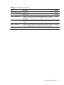
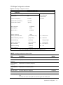
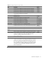
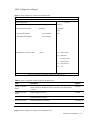
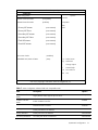
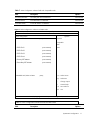
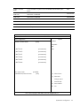
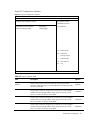
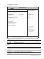
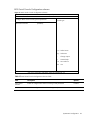
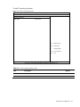
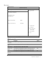
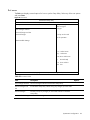
HP ProLiant DL288 G6 Server
Software Configuration Guide
Part number 663205-001
First edition July 2011
Legal notices
© Copyright 2011 Hewlett-Packard Development Company, L.P.
The information contained herein is subject to change without notice. The only warranties for HP products and services are
set forth in the express warranty statements accompanying such products and services. Nothing herein should be construed
as constituting an additional warranty. HP shall not be liable for technical or editorial errors or omissions contained herein.
Microsoft® and Windows® are U.S. registered trademarks of Microsoft Corporation. Intel® and Xeon® are trademarks of
Intel Corporation in the U.S. and other countries.
Contents
System BIOS configuration .................................................................................................................... 4
System BIOS overview ................................................................................................................................. 4
AMIBIOS software ...................................................................................................................................... 4
AMIBIOS Setup Utility ................................................................................................................................. 4
Accessing the Setup Utility ...................................................................................................................... 5
Navigating through the Setup Utility......................................................................................................... 5
Setup Utility menus ................................................................................................................................. 6
Recording custom setup values .............................................................................................................. 39
Loading system defaults ........................................................................................................................ 39
Clearing CMOS .................................................................................................................................. 39
BIOS Recovery Steps ............................................................................................................................ 40
Power-On Self Test (POST) ......................................................................................................................... 40
POST error indicators ........................................................................................................................... 41
POST-related troubleshooting ................................................................................................................ 42
OS installation ................................................................................................................................... 44
Supported OSes ....................................................................................................................................... 44
OS pre-installation procedure ..................................................................................................................... 44
Hardware setup ................................................................................................................................... 44
BIOS update ....................................................................................................................................... 44
Server management............................................................................................................................ 45
Pre- and post-installation procedures ........................................................................................................... 45
Pre-installation procedures .................................................................................................................... 45
Post-installation procedures ................................................................................................................... 46
Configuring the BMC ................................................................................................................................ 46
BMC Recovery Steps ................................................................................................................................. 47
SETSYS Utility ........................................................................................................................................... 48
Index ................................................................................................................................................ 49
Contents
3
System BIOS configuration
This chapter describes the basic functions of the AMIBIOS software.
System BIOS overview
A Basic Input/Output System, or BIOS, is a set of programs permanently stored in an EEPROM
chipset located on the system board. These programs serve as an interface between the server’s
hardware components and its operating system. This HP ProLiant DL288 G6 server features the
AMIBIOS software—a ROM BIOS-based diagnostic tool that monitors system activity and performs
constant hardware testing to ensure proper system operation.
AMIBIOS software
The AMIBIOS software serves three functions:
•
Configure the system settings via the AMIBIOS Setup Utility
Using the Setup Utility, you can install, configure, and optimize the hardware devices on your
system (such as clock, memory, and hard drives).
•
Initialize hardware at boot via POST routines
At power-on or reset, the software performs Power-On Self Test (POST) routines to test system
resources and run the operating system.
•
Perform run-time routines
Using the software, perform basic hardware routines that can be called from DOS and Microsoft
Windows applications.
AMIBIOS Setup Utility
NOTE: For ease of reading, the AMIBIOS Setup Utility will be referred to as “Setup” or “Setup
Utility” in this guide. Also, the screenshots used in this guide display default system values. These
values may not be the same as those in your server.
The AMIBIOS Setup Utility is a hardware configuration program built into the server BIOS. Because
most systems are already properly configured and optimized, there is normally no need to run this
utility.
You need to run this utility under the following conditions:
•
When changing the system configuration, including:
○
○
○
○
○
Setting the system time and date
Configuring the hard drives
Specifying the boot device sequence
Configuring the power management modes
Setting up system passwords or making other changes to the security setup
System BIOS configuration
4
•
When a configuration error is detected by the system and you are prompted by a "Run Setup"
message to make changes to the BIOS settings.
NOTE: If you repeatedly receive “Run Setup” messages, the battery located on the system board
may be defective. In this case, the system cannot retain configuration values in CMOS. Ask a
qualified technician for assistance.
The Setup Utility loads the configuration values in a battery-backed nonvolatile memory called CMOS
RAM. This memory area is not part of the system RAM, which allows configuration data to be
retained when power is turned off. The values take effect when the system is booted. POST uses these
values to configure the hardware. If the values and the actual hardware do not agree, POST
generates an error message. You must run the Setup Utility to change the BIOS settings from the
default or current configuration.
Accessing the Setup Utility
1.
Turn on the monitor and the server.
If the server is already turned on, save your data and exit all open applications, and then restart
the server.
During POST, press F10. If you fail to press F10 before POST is completed, you need to restart
the server and repeat this step. The first page displayed is the Main menu. Use the left (←) and
right (→) arrow keys to move between selections on the menu bar.
Navigating through the Setup Utility
Use the keys listed in the legend bar on the bottom of the Setup Utility screen to access the various
menu and submenu screens of the Setup Utility. Table 1 lists these legend keys and their respective
functions.
Table 1 Setup Utility Navigation Keys
Key
Function
← and →
Select different screens.
↑ and ↓
Select items in each menu.
Enter, Tab, or
Shift-Tab
Select a field value or display a submenu screen.
Esc
Exit the CMOS Setup menu.
<+>, <–>
Configure the system time or change field.
F1
To bring up the General Help window.
Display more options for items marked with
.
The General Help window describes other Setup navigation keys that are not displayed
on the legend bar.
F10
To save changes and exit the CMOS Setup Utility.
System BIOS configuration
5
Setup Utility menus
The Setup Utility menu bar displays the five primary menu selections. For detailed information and
screenshots of these Setup Utility menus and their related submenus, refer to the following sections.
Main menu
Figure 1 Main menu
ROM-based Setup Utility
<Main>
<Advanced>
Boot
Security
Exit
System Overview
Use [ENTER], [TAB]
or [SHIFT-TAB] to
Product Name:
ProLiant DL288 G6
select a field.
ProLiant BIOS:
O33
Build Date:
03/31/2010
Use [+] or [-] to
ROM ID
18DIM200
configure system time.
Processor
Intel(R) Xeon(R) CPU
E5640 @ 2.67GHz
Speed:
2666MHz
Count:
1
←→ Select Screen
System Memory
Size:
2048MB
↑↓ Select Item
+-
Change Field
System Time
[02:52:30]
Tab Select Field
System Date
[Thu 03/18/2010]
F1
System Serial Number
General Help
F10 Save and Exit
NIC#1 MAC Address
F4-CE-46-80-04-86
NIC#2 MAC Address
F4-CE-46-80-04-87
ESC Exit
V02. 61(C) Copyright 1985-2006, American Megatrends, Inc.
NOTE: The time is in 24-hour format. For example, 5:30 A.M. appears as 05:30:00, and 5:30, P.M. as
17:30:00.
System BIOS configuration
6
Table 2 Main menu fields
Field
Description
Options
Product Name
Display the product name of the system.
ProLiant BIOS
Display the BIOS family.
Build Date
Display the date when this version of BIOS was built.
ROM ID
Display the ID of the ROM.
Processor
Display the detailed processor information.
System Memory
Displays the amount of conventional memory detected during POST.
System Time
Adjust the system time.
System Date
Adjust the system date.
System Serial
Number
Display the System Serial Number.
NIC#1 MAC
Address
Display the MAC address of NIC1.
NIC#2 MAC
Address
Display the MAC address of NIC2.
Asset Tag
Configure asset tag settings.
POST F1 Prompt Set this value to allow wait of up to 15 seconds for an F1 press. This is the default
setting
Delayed
Set this value to wait indefinitely for an F1 press.
Enable
Set this value to continue booting without waiting for an F1 press.
Disabled
System BIOS configuration
7
Advanced menu
Figure 2 Advanced menu
ROM-based Setup Utility
Main
<Advanced>
Boot
Security
Exit
Advanced Settings
Custom: Allow to
WARNING: Setting wrong values in below sections
configure Efficiency
may cause system to malfunction.
/Performance related
items individually.
Efficiency
Power Efficiency Mode
[Efficiency]
/Performance: Impact
Power Supply Redundancy Mode
[High Efficiency]
groups as CPU
> CPU Configuration
Configuration/CPU
> CPU Bridge Configuration
bridge Configuration
> SATA Configuration
/PCI Express
> SuperIO Configuration
Configuration
> USB Configuration
> PCI Configuration
←→ Select Screen
> PCI Express Configuration
↑↓ Select Item
> IPMI Configuration
+-
Change Option
> BIOS Serial Console Configuration
F1
General Help
> Trusted Computing
F10
Save and Exit
ESC
Exit
V02. 61(C) Copyright 1985-2006, American Megatrends, Inc.
NOTE: The CPU Configuration setup screen can vary depending on the installed processor.
Table 3 Advanced menu fields
Field
Description
Options
Power Efficiency BIOS will initialize all power related processor and chipset settings to maximize
Mode
the performance per Watt value as measured by SpecPower.
CPU
Configuration
Efficiency
BIOS will initialize all power related processor and chipset settings to maximize
the performance of the server.
Performance
The user has modified the configuration of power/performance related settings
individually. User selection of this option is not allowed, It is only informational
based on other changes the user has made to SETUP options. When user set
"Power Efficiency Mode" to Custom, the user can change all power related
processor and chipset settings freely.
Custom
Configure advanced CPU settings.
System BIOS configuration
8
Table 3 Advanced menu fields
Field
Description
CPU Bridge
Configuration
Configure CPU Bridge chipset settings.
SATA
Configuration
Configure SATA device settings.
SuperIO
Configuration
Configure PILOT Super I/O chipset settings.
USB
Configuration
Configure USB controller settings.
PCI
Configuration
Configure PCI settings.
PCI Express
Configuration
Configure PCI Express settings.
IPMI
Configuration
Configure IPMI 2.0 settings.
BIOS Serial
Console
Configuration
Configure BIOS Serial Console settings.
Trusted
Computing
Configure Trusted Computing settings.
Options
System BIOS configuration
9
CPU Configuration submenu
Figure 3 CPU Configuration submenu
ROM-based Setup Utility
<Advanced>
Configure advanced CPU settings
When enabled, a VMM
Module Version: 01.09
can utilize the
Manufacturer:
provided by Intel(R)
additional HW Caps
Intel
Intel(R) Xeon(R) CPU
E5640 @ 2.67GHz
Virtualization Tech.
Frequency:
2.66GHz
Note: A full reset is
BCLK Speed:
133MHz
required to change
Cache L1:
256 KB
the setting.
Cache L2:
1024 KB
Cache L3:
12288KB
C1E Support
[Enabled]
Hardware Prefetcher
[Enabled]
←→ Select Screen
Adjacent Cache Line Prefetch
[Enabled]
↑↓ Select Item
DCU Prefetcher
[Enabled]
+-
Change Option
Data Reuse
[Enabled]
F1
General Help
Intel VT-d
[Enabled]
F10
Save and Exit
Intel (R) Virtualization Tech
[Enabled]
ESC
Exit
Execute-Disable Bit Capability
[Enabled]
Intel (R) HT Technology
[Enabled]
V02. 61(C) Copyright 1985-2006, American Megatrends, Inc.
Table 4 CPU Configuration submenu fields
Field
Description
Module Version
Display the module version of the processor.
Manufacture
Display the manufacture of the processor.
Frequency
Display the frequency of the processor.
BCLK Speed
Display the BCLK speed of the processor.
Cache
Display the cache of the processor.
C1E Support
C1E (Extended HALT state) enabled via the BIOS. This is the default
setting.
Enabled
Disables support for adjacent cache line prefetch debug function.
Disabled
Enable the hardware components that are used in conjunction with
software programs to prefetch data in order to shorten execution cycles
and maximize data processing efficiency.
Enabled
Hardware Prefetcher
Options
System BIOS configuration
10
Table 4 CPU Configuration submenu fields
Field
Adjacent Cache Line
Prefetch
DCU Prefetcher
Data Reuse
Description
Options
Disable the hardware components that are used in conjunction with
software programs to prefetcher data in order to shorten execution cycles
and maximize data processing efficiency.
Disabled
Enable the Adjacent Cache Line Prefetch feature. This is the default
setting.
Enabled
Disable the Adjacent Cache Line Prefetch feature.
Disabled
Enabling the DCU Prefetcher is intended to speed up data accessed by a
program by prefetching to the L1 data cache. DCU prefetching improves
performance if data in large structures is arranged sequentially in the
order used by the program.
Enabled
If data access patterns are sparse instead of local, some performance
degradation can occur under high CPU load due to bandwidth issues. In
such cases, disabling DCU Prefetcher may improve performance.
Disabled
Data Reuse reduces the frequency of L3 cache updates from the L1
cache. In most cases, this improves performance by reducing the internal
bandwidth consumed by constant updates of L1 cache lines in the L3
cache.
Enabled
However, since this behavior can result in more requests to main
Disabled
memory, in some cases, overall performance may be degraded. Whether
Data Reuse should be enabled or disabled for a particular workload will
depend on the memory access patterns of the workload.
Intel VT-d
Enable Intel's Virtualization Technology support for Direct I/O VT-d. This
feature offers fully-protected I/O resource-sharing across the Intel
platforms, providing the user with greater reliability, security and
availability in networking and data-sharing.
Enabled
Disable VT-d.
Disabled
Intel (R) Virtualization Tech Turn on hardware virtualization support. A full system reset is required
after changing this value.
Enabled
Turn off hardware virtualization support. A full system reset is required
after changing this value.
Disabled
When enabled, train the XD feature flag to always return 0. This is the
default setting.
Enabled
When disabled, force the XD feature flag to always return 0
Disabled
Enable Simultaneous Multi-Threading.
Enabled
Disable Simultaneous Multi-Threading.
Disabled
All cores active.
All
1 core active.
1
2 cores active.
2
Enable A20M (when needed for legacy OSes / applications)
Enabled
Disable A20M
Disabled
Execute-Disable Bit
Capability
Intel (R) HT Technology
Active Processor Cores
A20M
System BIOS configuration
11
Table 4 CPU Configuration submenu fields
Field
Description
Options
Intel(R) SpeedStep(tm) tech
Enable GV3.
Enabled
Disable GV3.
Disabled
Enable processor cores to run faster than marked frequency in specific
conditions. Note that SpeedStep must be enabled in order to enable
TurboMode.
Enabled
Disable processor cores to run faster than marked frequency in specific
conditions
Disabled
Enable CPU idle C2/C3/C4. Enabling it will allow the OS to make the
cores run at different frequencies, thus making optimum use of power.
Enabled
Disable CPU idle C2/C3/C4. Cores will run at the same frequency.
Disabled
Intel(R) TurboMode tech
Intel(R) C-STATE tech
System BIOS configuration
12
CPU Bridge Configuration submenu
Figure 4 CPU Bridge Configuration submenu
ROM-based Setup Utility
<Advanced>
CPU Bridge Chipset Configuration submenu
To transfer the QPI
CPU Revision
A0
Links to full-speed
Current QPI Frequency
5.866GT
slow-mode
Current Memory Frequency
1333 Mhz
Current Memory Mode
or leave them in
Sparing
QPI Links Speed
[Full-Speed]
QPI Frequency
[Auto]
QPI L0s and L1
[Enabled]
Memory Frequency
[Auto]
Memory Speed with 20PC
[[email protected]]
←→ Select Screen
Advanced Memory Protection
[Independent]
↑↓ Select Item
Note Interleaving
[Disabled]
+-
Change Option
Memory Interleaving
[Full Interleaving]
F1
General Help
QPI Optimization
[Balanced]
F10
Save and Exit
Demand Scrubbing
[Enabled]
ESC
Exit
Patrol Scrubbing
[Disabled]
V02. 61(C) Copyright 1985-2006, American Megatrends, Inc.
Table 5 CPU Bridge Configuration submenu fields
Field
Description
CPU Revision
Display the CPU revision.
Current QPI
Frequency
Display the current QPI frequency.
Current Memory
Frequency
Display the current memory frequency.
Current Memory
Mode
Display the current memory mode.
QPI Links Speed
Transit the QPI links to full-speed.
Full-Speed
Transit the QPI links to slow mode
Slow Mode
QuickPath Interconnect (QPI) is the connection between the CPUs and I/O
hub.
Auto
QPI Frequency
Options
Transit the links to the auto speed when transitioning the links to full-speed.
System BIOS configuration
13
Table 5 CPU Bridge Configuration submenu fields
Field
QPI L0s and L1
Description
Options
Transit the links to 4.800GT when transitioning the links to full-speed.
4.800GT
Transit the links to 5.866GT when transitioning the links to full-speed.
5.866GT
Transit the links to 6.400GT when transitioning the links to full-speed.
6.400GT
This enables the QPI power state to lower power consumption. L0s and L1
are automatically selected by the motherboard.
Enabled
Enabled L0s and L1.
Disabled L0s and L1.
Disabled
Memory Frequency Transit the memory frequency to the maximum speed.
Memory Mode
Memory Inter
leaving
Auto
Transit the memory frequency to the 800MHz.
Force DDR-800
Transit the memory frequency to the 1066MHz.
Force DDR-1066
Transit the memory frequency to the 1333MHz.
Force DDR-1333
Configure the memory to work in independent channel.
Independent
Configure the memory to work in mirrors channel space between channels.
Channel
Mirroring
Configure the memory with Lockstep between channel 0 and 1.
Lockstep
Memory controller should be configured as interleaved whenever possible.
Enabled
Memory controller should be configured as interleaved whenever possible.
Disabled
Demand Scrubbing Demand scrubbing solves the problem of obtaining multiple correctable
errors due to a single soft error, and thus the problem of potentially
reporting a correctable threshold error due to soft errors.
Enabled
Allow to scrub ECC demand.
Patrol Scrubbing
Disable to scrub ECC demand.
Disabled
Background scrubbing (also known as patrol scrubbing) is a memory errorcorrection scheme that works in the background looking for and correcting
resident errors. Instead of only reading the data and ECC bits, correcting
them, and writing them back to memory when a correctable memory error
occurs, the system will constantly be reading and writing memory locations.
Thus, the system will be constantly scrubbing all of the contents of memory
in an effort to correct soft errors before a correctable error even occurs.
Enabled
Allow to scrub ECC patrol.
Disable to scrub ECC patrol.
Disabled
System BIOS configuration
14
SATA Configuration submenu
Figure 5 SATA Configuration submenu with Disabled mode
ROM-based Setup Utility
<Advanced>
Options
SATA Configuration
SATA#1 Controller Mode
[Disabled]
SATA#2 Controller Mode
[Enabled]
Disabled
Compatible
RAID
> Primary IDE Master:
[Not Detected]
> Secondary IDE Master:
[Not Detected]
Embedded SAS/SATA Link Rate
[Auto]
AHCI
←→ Select Screen
↑↓ Select Item
+-
Change Option
F1
General Help
F10
Save and Exit
ESC
Exit
V02. 61(C) Copyright 1985-2006, American Megatrends, Inc.
Table 6 SATA Configuration submenu fields with Disabled mode
Field
Description
Options
SATA#1 Controller
Mode
SATA controller is disabled and does not appear in the standard boot
order list.
Disabled
SATA#2 Controller
Mode
Enable SATA#2 Controller.
Enabled
Disable SATA#2 Controller.
Disabled
Primary IDE Master
Primary IDE Master not detected.
Not Detected
Secondary IDE Master
Secondary IDE Master not detected.
Not Detected
Figure 6 SATA Configuration submenu with Compatible mode
System BIOS configuration
15
ROM-based Setup Utility
<Advanced>
Options
SATA Configuration
SATA#1 Controller Mode
[Compatible]
SATA#2 Controller Mode
[Enabled]
Disabled
Compatible
RAID
> Primary IDE Master:
[Not Detected]
> Primary IDE Slave:
[Not Detected]
> Secondary IDE Master:
[Not Detected]
> Secondary IDE Slave:
[Not Detected]
> Third IDE Master:
[Not Detected]
> Fourth IDE Master:
[Not Detected]
Drive Write Cache
[Disabled]
Embedded SAS/SATA Link Rate
[Auto]
AHCI
←→ Select Screen
↑↓ Select Item
+-
Change Option
F1
General Help
F10
Save and Exit
ESC
Exit
V02. 61(C) Copyright 1985-2006, American Megatrends, Inc.
Table 7 SATA Configuration submenu fields with Compatible mode
Field
Description
Options
SATA#1 Controller
Mode
Legacy Native mode, supports up to 4 drives.
Compatible
SATA#2 Controller
Mode
Enable SATA#2 Controller.
Enabled
Disable SATA#2 Controller.
Disabled
Primary IDE Master
Primary IDE Master not detected.
Not Detected
Primary IDE Slave
Primary IDE slave not detected.
Not Detected
Secondary IDE Master
Secondary IDE Master not detected.
Not Detected
System BIOS configuration
16
Table 7 SATA Configuration submenu fields with Compatible mode
Field
Description
Options
Secondary IDE Slave
Secondary IDE slave not detected.
Not Detected
Third IDE Master
Third IDE Master not detected.
Not Detected
Fourth IDE Master
Fourth IDE Master not detected.
Not Detected
Figure 7 SATA Configuration submenu with RAID mode
ROM-based Setup Utility
<Advanced>
Options
SATA Configuration
SATA#1 Controller Mode
[RAID]
Disabled
Compatible
RAID
> SATA Port1:
[Not Detected]
> SATA Port2:
[Not Detected]
> SATA Port3:
[Not Detected]
> SATA Port4:
[Not Detected]
> Primary IDE Master:
[Not Detected]
> Secondary IDE Master:
[Not Detected]
Embedded SAS/SATA Link Rate
[Auto]
AHCI
←→ Select Screen
↑↓ Select Item
+-
Change Option
F1
General Help
F10
Save and Exit
ESC
Exit
V02. 61(C) Copyright 1985-2006, American Megatrends, Inc.
Table 8 SATA Configuration submenu fields with RAID mode
Field
Description
Options
System BIOS configuration
17
SATA#1 Controller
Mode
L Only available on systems with an embedded software RAID option
ROM.
RAID
SATA Port1
SATA Port1 not detected.
Not Detected
SATA Port2
SATA Port2 not detected.
Not Detected
SATA Port3
SATA Port3 not detected.
Not Detected
SATA Port4
SATA Port4 not detected.
Not Detected
Primary IDE Master
Primary IDE Master not detected.
Not Detected
Secondary IDE Master
Secondary IDE Master not detected.
Not Detected
ROM-based Setup Utility
<Advanced>
Options
SATA Configuration
SATA#1 Controller Mode
[AHCI]
Disabled
Compatible
RAID
> AHCI Port1:
[Not Detected]
> AHCI Port2:
[Not Detected]
> AHCI Por3:
[Not Detected]
> AHCI Port4:
[Not Detected]
> AHCI Port5:
[Not Detected]
> AHCI Port6:
[Not Detected]
Drive Write Cache
AHCI
[Disabled]
Embedded SAS/SATA Link Rate
[Auto]
←→ Select Screen
↑↓ Select Item
+-
Change Option
F1
General Help
F10
Save and Exit
ESC
Exit
V02. 61(C) Copyright 1985-2006, American Megatrends, Inc.
System BIOS configuration
18
Table 9 SATA Configuration submenu fields with AHCI
Field
Description
Options
SATA#1 Controller
Mode
This should be the DEFAULT if NCQ Mode requires that AHCI also be
enabled. Otherwise, legacy SATA Native Mode should be the DEFAULT
as previously specified.
AHCI
AHCI Port1
AHCI Port1 not detected.
Not Detected
AHCI Port2
AHCI Port2 not detected.
Not Detected
AHCI Port3
AHCI Port3 not detected.
Not Detected
AHCI Port4
AHCI Port4 not detected.
Not Detected
AHCI Port5
AHCI Port5 not detected.
Not Detected
AHCI Port6
AHCI Port6 not detected.
Not Detected
System BIOS configuration
19
Super IO Configuration submenu
Figure 8 Super IO Configuration submenu
ROM-based Setup Utility
<Advanced>
Allows BIOS to Select
Configure PILOT Super IO Chipset
Embedded Serial Port
Embedded Serial Port Address
[3F8/IRQ4]
Serial Port Interrupt setting
[Edge trigger]
Base Addresses.
←→ Select Screen
↑↓ Select Item
+-
Change Option
F1
General Help
F10
Save and Exit
ESC
Exit
V02. 61(C) Copyright 1985-2006, American Megatrends, Inc.
Table 10 Super IO submenu fields
Field
Description
Options
Embedded Serial Port
Address
Set this value to prevent the serial port from accessing any system
resources. When this option is set to Disabled, the serial port physically
becomes unavailable.
Disabled
Set this value to allow the serial port to use 2F8 as its I/O port address
and IRQ 3 for the interrupt address. If the system will not use a serial
device, it is best to set this port to Disabled.
2F8/IRQ3
Set this value to allow the serial port to use 3E8 as its I/O port address
and IRQ 4 for the interrupt address. If the system will not use a serial
device, it is best to set this port to Disabled.
3E8/IRQ4
Set this value to allow the serial port to use 2E8 as its I/O port address
and IRQ 3 for the interrupt address. If the system will not use a serial
device, it is best to set this port to Disabled.
2E8/IRQ3
System BIOS configuration
20
Table 10 Super IO submenu fields
Field
Description
Options
Set this value to allow the serial port to use 3F8 as its I/O port address
and IRQ 4 for the interrupt address. This is the default setting. The
majority of serial port 1 or COM1 ports on computer systems use IRQ4
3F8/IRQ4
and I/O Port 3F8 as the standard setting. The most common serial device
connected to this port is a mouse. If the system will not use a serial
device, it is best to set this port to Disabled.
System BIOS configuration
21
USB Configuration submenu
Figure 9 USB Configuration submenu
ROM-based Setup Utility
<Advanced>
Options
USB Configuration
Module Version – 2.24. 4-13.4
Disabled
Enabled
USB Devices Enabled:
1 Keyboard, 2 Mouse, 1 Drive
USB Functions
[Enabled]
Legacy USB Support
[Enabled]
USB 2.0 Controller
[Enabled]
USB 2.0 Controller Mode
[HiSpeed]
BIOS EHCI Hand-Off
[Enabled]
Hot-plug USB FDD Support
[Auto]
←→ Select Screen
↑↓ Select Item
> USB Mass Storage Device Configuration
+-
Change Option
F1
General Help
F10
Save and Exit
ESC
Exit
V02. 61(C) Copyright 1985-2006, American Megatrends, Inc.
Table 11 USB Configuration submenu fields
Field
Description
Module Version
Display USB module version.
USB Devices Enabled
Display the enabled USB devices in system.
USB Functions
Enable USB functions.
Enabled
Disable USB functions.
Disabled
Enable support for Legacy USB devices.
Enabled
Disable support for Legacy USB devices.
Disabled
Disable legacy support if no USB devices are connected.
Auto
Enable USB 2.0 support.
Enabled
Disable USB 2.0 support.
Disabled
Set the USB 2.0 Controller to full-speed.
FullSpeed
Legacy USB Support:
USB 2.0 Controller:
USB 2.0 Controller Mode:
Options
System BIOS configuration
22
Table 11 USB Configuration submenu fields
Field
BIOS EHCI Hand-Off
Description
Options
Set the USB 2.0 Controller to high-speed.
HiSpeed
Set this value to enable EHCI hand-off support. This is the default value.
Enabled
Set this value to disable EHCI hand-off support. This is used when your
OS does not support EHCI hand-off.
Disabled
Hot-plug USB FDD Support Set this value to enable Hot-plug USB FDD support.
USB Mass Storage Device
Configuration
Enabled
Clear this value to disable Hot-plug USB FDD support.
Disabled
Auto option creates this dummy device only if there is no FDD present.
Auto
Access the submenu to configure USB Mass Storage Device.
System BIOS configuration
23
PCI Configuration submenu
Figure 10 PCI Configuration submenu
ROM-based Setup Utility
<Advanced>
Select which graphics
PCI Configuration
controller to use as
Embedded VGA Control
[Auto Detect]
the primary boot
device.
Embedded NIC Port 1 Control
[Enabled]
Embedded NIC Port 1 PXE
[Enabled]
Embedded NIC Port 2 Control
[Enabled]
Embedded NIC Port 2 PXE
[Disabled]
Wake-On LAN
[Enabled]
←→ Select Screen
↑↓ Select Item
+-
Change Option
F1
General Help
F10
Save and Exit
ESC
Exit
V02. 61(C) Copyright 1985-2006, American Megatrends, Inc.
Table 12 PCI Configuration submenu fields
Field
Description
Options
Embedded VGA Control
Always Enable Onboard VGA.
Always
Enabled
Enable add-in VGA once there is add-in VGA.
Auto Detect
Enable Onboard NIC1.
Enabled
Disable Onboard NIC1.
Disabled
Embedded NIC Port 1
Control
Embedded NIC Port 1 PXE Enable Onboard NIC1 PXE.
Enabled
Disable Onboard NIC1 PXE.
Disabled
Enable Onboard NIC2.
Enabled
Disable Onboard NIC2.
Disabled
Embedded NIC Port 2
Control
System BIOS configuration
24
Table 12 PCI Configuration submenu fields
Field
Description
Options
Embedded NIC Port 2 PXE Enable Onboard NIC2 PXE.
Enabled
Disable Onboard NIC2 PXE.
Disabled
Allow wake up in S4/S5 over LAN. This is the default setting.
Enabled
Disabled Wake-On LAN in S4/S5.
Disabled
Wake-On LAN
System BIOS configuration
25
PCI Express Configuration submenu
Figure 11 PCI Express Configuration submenu
ROM-based Setup Utility
<Advanced>
PCI Express Configuration
Active State Power-Management
[Disabled]
PCI Express Gen2
[Gen2]
←→ Select Screen
↑↓ Select Item
F1
General Help
F10
Save and Exit
ESC
Exit
V02. 61 (C) Copyright 1985-2006, American Megatrends, Inc.
Table 13 PCI Express Configuration submenu fields
Field
Description
Options
Active State Power
Management
Enable the PCIE ports to enter L0s and/or L1 states.
Enabled
Disable PCI Express L0s and L1 link power states. This option would be
chosen by the user if there were compatibility issues with their PCIE option
cards. It is the default setting.
Disabled
All PCI-E devices will only run in Gen 1 mode.
Gen 1
For best possible performance. PCI-E devices, which support Gen 2 mode,
will run in Gen 2 mode. PCI-E devices, which only support Gen 1 mode,
will run in Gen 1 mode.
Gen 2
PCI Express Gen2
System BIOS configuration
26
IPMI Configuration submenu
Figure 12 IPMI Configuration submenu
ROM-based Setup Utility
<Advanced>
InPut for Set LAN
IPMI 2.0 Configuration
Configuration command.
Status of BMC
Working
BMC Firmware Revision
09.57
BMC/IPMI FW Date:
Jan/13/2010
this group may take
BMC SDR Version:
2.19.0.211
considerable amount of
Warehouse Build Number: 211
NOTE: Each question in
time.
>Set LAN Configuration
>SEL Configuration
>Hardware Health Information
>Watchdog Configuration
>Serial Port Configuration
←→ Select Screen
↑↓ Select Item
Enter Go to Sub Screen
F1
General Help
F10
Save and Exit
ESC
Exit
V02. 61(C) Copyright 1985-2006, American Megatrends, Inc.
Table 14 IPMI Configuration submenu fields
Field
Description
Status of BMC
Display the current status of BMC.
BMC Firmware
Revision
Display the current revision of the BMC firmware.
Options
BMC/IPMI FW Date Display the date of the BMC/IPMI firmware.
BMC SDR Version
Display the current version of the BMC SDR.
Set LAN
Configuration
Access the submenu to configure Option of Set LAN Configuration.
SEL Configuration
Access the submenu to configure Option of SEL Configuration.
Serial Port
Configuration
Access the submenu to configure Option of Serial Port Configuration.
System BIOS configuration
27
Table 14 IPMI Configuration submenu fields
Field
Description
Options
Watch Dog
Configuration
Access the submenu to configure Option of Watch Dog Configuration.
Hardware Health
Status
Access the submenu to view Hardware Health Status.
System BIOS configuration
28
BIOS Serial Console Configuration submenu
Figure 13 BIOS Serial Console Configuration submenu
ROM-based Setup Utility
<Advanced>
Configure BIOS Serial Console type and parameters
Select BIOS Serial
Console type.
BIOS Serial Console
[Disabled]
←→ Select Screen
↑↓ Select Item
+-
Change Option
F1
General Help
F10
Save and Exit
ESC
Exit
V02. 61(C) Copyright 1985-2006, American Megatrends, Inc.
Table 15 BIOS Serial Console Configuration submenu fields
Field
Description
Options
BIOS Serial
Console
Enable to configure BIOS Serial Console type and parameters
Enabled
Disable to configure BIOS Serial Console type and parameters
Disabled
System BIOS configuration
29
Trusted Computing submenu
Figure 14 Trusted Computing submenu
ROM-based Setup Utility
<Advanced>
Trusted Computing
TPM Status
Not Present
←→ Select Screen
↑↓ Select Item
F1
General Help
F10
Save and Exit
ESC
Exit
V02. 61(C) Copyright 1985-2006, American Megatrends, Inc.
Table 16 Trusted Computing submenu fields
Field
Description
Options
TPM Status
TPM not present
Not Present
Display TPM Status.
Present
System BIOS configuration
30
Boot menu
Figure 15 Boot menu
ROM-based Setup Utility
Main
Advanced
<Boot>
Security
Exit
Configure Settings
Boot Settings
during System Boot.
> Boot Settings Configuration
>Standard Boot Order
>Hard Disk Drives
USB Device Boot Priority
[High]
Restore on AC Power Loss
[Last State]
←→ Select Screen
↑↓ Select Item
Enter Go to Sub Screen
F1
General Help
F10 Save and Exit
ESC Exit
V02. 61(C) Copyright 1985-2006, American Megatrends, Inc.
Table 17 Boot menu fields
Field
Description
Boot Settings
Configuration
Configure settings during system boot.
Standard Boot
Order
View and configure standard boot order settings.
Hard Disk Drives
Display HDD information if detect HDD installed.
USB Device Boot
Priority
Force USB devices automatically showing up as top priority within their
device class in the standard boot order list. This is the default setting.
High
Train USB devices as original priority as the standard boot order list.
Low
Power off the server after power loss.
Power off
Power on the server after power loss.
Power on
Restore on AC
Power Loss
Options
System BIOS configuration
31
Table 17 Boot menu fields
Field
Description
Options
Restore last state after power loss.
Last state
System BIOS configuration
32
Boot Settings Configuration submenu
Figure 16 Boot Setting Configuration submenu
ROM-based Setup Utility
<Boot>
Allows BIOS to skip
Boot Settings Configuration
certain tests while
Quick Boot
[Enabled]
booting. This will
Quiet Boot
[Enabled]
decrease the time
Num Lock
[Enabled]
needed to boot the
system.
←→ Select Screen
↑↓ Select Item
+F1
Change Option
General Help
F10 Save and Exit
ESC Exit
V02. 61(C) Copyright 1985-2006, American Megatrends, Inc.
Table 18 Boot Settings Configuration submenu fields
Field
Description
Options
Quick Boot
Allow BIOS to skip certain tests while booting. This will decrease the time
needed to boot the system.
Enabled
Allow the BIOS to process the normal tests while booting.
Disabled
Display OEM Logo instead of POST messages
Enabled
Display normal POST messages. This is the default setting.
Disabled
Set this value to allow Num Lock on the keyboard to be enabled
automatically when the computer system is booted up. This allows the
immediate use of the numeric keypad located on the right side of the
keyboard. To confirm this, the Num Lock LED on the keyboard will be lit.
Enabled
Quiet Boot
Num Lock
System BIOS configuration
33
Table 18 Boot Settings Configuration submenu fields
Field
Description
Options
This option does not enable the keyboard Num Lock automatically. To use
the numeric keypad, press the Num Lock key located on the upper left-hand
corner of the numeric keypad. The Num Lock LED on the keyboard will light
up when Num lock is engaged. This is the default setting.
Disabled
System BIOS configuration
34
Standard Boot Order submenu
Figure 17 Standard Boot Order submenu
ROM-based Setup Utility
<Boot>
Specifies the boot
Standard Boot Order
sequence from the
1st Boot Device
[Hard Drive]
2nd Boot Device
[Network:IBA GE Slo]
available devices.
A device enclosed in
parenthesis has been
disabled in the
corresponding type
menu.
←→ Select Screen
↑↓ Select Item
+F1
Change Option
General Help
F10 Save and Exit
ESC Exit
V02. 61(C) Copyright 1985-2006, American Megatrends, Inc.
Table 19 Standard Boot Order submenu fields
Field
Description
Options
1st Boot Device
Hard drive is the1st boot device.
Hard drive
2nd Boot Device
Network:IBA GE Slo is the 2nd boot device.
Network:IBA GE
Slo
System BIOS configuration
35
Hard Disk Drives submenu
Figure 18 Hard Disk Drives submenu
ROM-based Setup Utility
<Boot>
Specifies the boot
Hard Disk Drives
sequence from the
[SATA: 4M-GB0500C441]
1st Drive
available devices.
←→ Select Screen
↑↓ Select Item
+F1
Change Option
General Help
F10 Save and Exit
ESC Exit
V02. 61(C) Copyright 1985-2006, American Megatrends, Inc.
Table 20 Hard Disk Drives submenu fields
Field
Description
Options
1st Drive
USB disk is the 1st drive.
USB: SanDisk
USB F1
System BIOS configuration
36
Security menu
Figure 19 Security menu
ROM-based Setup Utility
Main
Advanced
Boot
<Security>
Exit
Install or Change the
Security Settings
Password.
Admin Password:
Not Installed
User Password:
Not Installed
Change Admin Password
Boot Sector Virus Protection:
[Disabled]
←→ Select Screen
↑↓ Select Item
Enter Change
F1
General Help
F10 Save and Exit
ESC Exit
V02. 61(C) Copyright 1985-2006, American Megatrends, Inc.
Table 21 Security menu fields
Field
Description
Options
Admin Password Is No Admin password is installed.
User Password Is
Not Installed
An Admin password is installed.
Installed
A user password is not installed.
Not Installed
A user password is installed.
Installed
Change Admin
Password
Type the Supervisor's password in the dialogue box to set or to change
Admin password, which allows access to the BIOS.
Boot Sector Virus
Protection
Enable boot sector virus protection.
Enabled
Disable boot sector virus protection.
Disabled
System BIOS configuration
37
Exit menu
The Exit menu displays several options for how to quit the Setup Utility. Select any of the exit options
and press Enter.
Figure 20 Exit menu
ROM-based Setup Utility
Main
Advanced
Boot
Security
<Exit>
Exit system setup
Exit Options
after saving the
changes.
Save Changes and Exit
Discard Changes and Exit
Discard Changes
F10 key can be used
for this operation..
Restore Default Settings
←→ Select Screen
↑↓ Select Item
Enter Go to Sub Screen
F1
General Help
F10 Save and Exit
ESC Exit
V02. 61(C) Copyright 1985-2006, American Megatrends, Inc.
Table 22 Exit menu fields
Field
Description
Options
Save Changes and Exit
Save the changes made and exit the BIOS Setup Utility.
Discard Changes and
Exit
Exit the BIOS Setup utility without saving any changes you have made.
Discard Changes
Discard (cancel) any changes you have made. Remain in the BIOS
Setup Utility.
Restore Default Settings
Restore Default Settings.
System BIOS configuration
38
Recording custom setup values
Write down the settings from the Setup Utility and keep them in a safe place. If you need to restore
the custom values, you must run the Setup Utility and then reenter these custom settings. Having a
record of these custom settings makes this much easier.
Loading system defaults
If the system fails after you make changes in the Setup Utility menus, reboot the server, enter Setup,
and load the system default settings to correct the error. These default settings have been selected to
optimize the server’s performance. Setup default settings are quite demanding in terms of resource
consumption. If you are using low-speed memory chips or other types of low-performance components
and you choose to load these settings, the system might not function properly.
To load the system defaults:
1.
Reboot the server in a normal manner.
2.
During POST, press F10 to access the Setup Utility.
3.
Press F9 to load the default values.
4.
Choose Save Changes and Exit on the Exit menu, and press Enter to save the changes and close
the Setup Utility.
Clearing CMOS
You may need to clear the Setup configuration values (CMOS) if the configuration has been
corrupted, or if incorrect settings made in the Setup Utility have caused error messages to be
unreadable. Clearing the CMOS data removes the supervisor password.
The clear CMOS setting is on the jumper block (J27-A) on the system board. Refer to your server hood
label or the HP ProLiant DL288 G6 Server Maintenance and Service Guide for the location of this
jumper block and the clear CMOS setting.
To clear CMOS:
1.
Perform the pre-installation procedures described on page 45.
2.
If necessary, remove any expansion boards, assemblies, or cables that prevent access to enable
CMOS jumper block (J27-A).
3.
Locate the clear CMOS jumper block (J27-A) on the system board.
4.
Enable clear CMOS jumper block (J27-A) to clear the CMOS memory.
5.
Perform the post-installation procedures as described on page 46.
6.
During POST, press F10 to access the Setup Utility.
7.
Press F9 to load the system default values.
8.
Set time, date, and other system values.
9.
Press F10 to save the changes you made and to close the Setup Utility.
System BIOS configuration
39
BIOS Recovery Steps
Steps to perform a BIOS recovery:
1.
Prepare USB key for BIOS recovery.
a. On a system with Internet access, download the ROMPaq file for the restore BIOS from
hp.com.
b. Run the ROMPaq file.
c.
After following the instructions to unpack the ROMPaq file, you will see the following in your
browser:
d. Follow the instructions to prepare your USB key with the proper BIOS files for restoration.
2.
Perform BIOS Recovery:
a. Place jumper on J27 - group C pins.
b.
Insert USB key.
c. Power on computer, and wait for the recovery process complete. Wait a minimum of 10
minutes for the process to complete.
d. Unplug USB key and remove jumper from J27 - group C pins.
e. Restart computer and load BIOS defaults.
Power-On Self Test (POST)
When the server boots up, a series of tests are displayed on the screen. This is referred to as PowerOn Self-Test (POST). POST is a series of diagnostic tests that checks firmware and assemblies to
ensure that the server is properly functioning. This diagnostic function automatically runs each time the
server is powered on.
These diagnostics, which reside in the BIOS ROM, isolate the server-related logic failures and indicate
the board or component that needs to be replaced, as indicated by the error messages. Most server
System BIOS configuration
40
hardware failures are accurately isolated during POST. The number of tests displayed depends on the
configuration of the server.
During POST you can:
•
•
•
•
Press ESC to skip the HP logo and go to POST boot progress display system summary screen.
Press F10 to access the Setup Utility.
Press F12 to request a network boot (PXE).
Press F1 to continue POST after POST errors are detected.
POST error indicators
When POST detects a system failure it displays a POST error message.
Recoverable POST errors
When a non-fatal error occurs during POST, the screen will display an error message with the format
“xxx-Error Identifier String” where “xxx” is a unique number code that matches ODM system specific
error documentation and may be a hexadecimal or decimal value.
All Error messages describe the problems as shown below:
Table 23 POST Error Messages
Error code
Description
10
Floppy Controller Failure
00B
CMOS Memory Size Wrong
00C
RAM R/W test failed
003
CMOS Battery Low
005
CMOS Checksum Bad
040
Refresh timer test failed
041
Display memory test failed
048
Password check failed
120
$A0CCMOS Cleared by Jumper. Restore the Jumper and Continue…
122
$A0CPassword Cleared By Jumper. Restore the Jumper and Continue…
150
Processor failed BIST
160
Processor missing microcode:
192
L3 cache size mismatch
193
CPUID, Processor stepping are different
194
CPUID, Processor family are different
195
Front side bus mismatch. System halted.
196
CPUID, Processor Model are different
197
Processor speeds mismatched
System BIOS configuration
41
Table 23 POST Error Messages
Error code
Description
198
Processor QPI speed mismatch detected.
601
Error: BMC Not Responding
605
BMC Has Detected Fatal Hardware Error
611
Internal User Area Of BMC FRU Corrupted
612
Controller Update 'boot block' Firmware Corrupted
613
Controller Operational Firmware Corrupted
620
Non-Redundant Fan Failure or Missing
621
Redundant Fan Configuration, One Fan Failure or Missing
622
Redundant Fan Configuration, Multiple Fans Failure or Missing
Temperature Violation Detected
623
Waiting 5 minutes for system to cool
Press ESC Key to resume booting without waiting for the system to cool
Warning: Pressing ESC is NOT recommended as the system may shutdown
unexpectedly
624
Power Supply Failure or Power Supply Unplugged
626
Update SDRR/Configuration Image failed
627
Invalid or Unknown SKU/Chassis ID
Please check Front panel, System ID Jumper or Riser card
Press F1 to Continue
628
Redundant Power Supply Mismatch
701
Insufficient Runtime space for MPS data.!!.
System may operate in PIC or Non-MPS mode.
702
No enough APIC ID in range 0-0Fh can be assigned to IO APICs.
(Re-assigning CPUs' local APIC ID may solve this issue)
MPS Table is not built! System may operate in PIC or Non-MPS mode.
POST-related troubleshooting
Perform the following procedures when POST fails to run, error messages are displayed.
If the POST failure is during a routine boot up, verify the following conditions:
•
•
•
All external cables and power cables are firmly plugged in.
•
•
•
•
The monitor's contrast and brightness settings are correct.
The power outlet to which the server is connected is working.
The server and monitor are both turned on. The bicolor power status LED indicator on the ear
must be green.
All internal cables are properly connected and all boards firmly seated.
The processor is fully seated in its socket on the system board.
The heat sink assembly is properly installed on top of the processor.
System BIOS configuration
42
•
•
•
•
All memory modules are properly installed.
If you have installed a PCI accessory board, verify that the board is firmly seated and any
jumpers on the board are properly set. Refer to the documentation provided with the accessory
board.
All internal cabling and connections are in their proper order.
If you have changed the jumper on the system board, verify that each is properly set.
If the POST failure occurs after installing an accessory, perform the following steps:
1.
Perform the pre-installation procedure described on page 45.
2.
If necessary, remove any expansion boards, assemblies, or cables that prevent access to the
system components.
3.
Check the following conditions:
a. If you have installed an expansion board, verify that the board is firmly seated in its slot and
any switches or jumpers on the board are properly set. Refer to the documentation provided
with the expansion board.
b. All internal cabling and connections are in their proper order.
c. If you have changed any jumper block on the system board, verify that each one is properly
set.
4.
Perform the post-installation procedure described on page 46.
5.
Turn on the monitor.
6.
If the server still does not work, repeat step 2.
7.
Remove all accessories, except the primary boot hard disk drive.
8.
Repeat steps 4 and 5.
If the server now works, replace the boards and accessories one at a time to determine which
one is causing the problem.
System BIOS configuration
43
OS installation
Supported OSes
Refer to the operating system support matrix (http://www.hp.com/go/supportos).
OS pre-installation procedure
Perform the two pre-OS installation steps in this section before installing the OS of your choice.
1.
Configure the hardware aspect of the server.
2.
Update the server BIOS.
Hardware setup
Prepare the server following the instructions in the HP ProLiant DL288 G6 Server Installation Sheet.
It is recommended that you do not install any third party adapter until you verify that the HP
equipment is functioning properly and you complete the OS installation.
Your HP ProLiant DL288 G6 server comes with new hard disk drive(s) that do not need specific setup.
However, if you install additional used hard disk drives in your new server:
•
Note that most OS installations remove all data from the hard disk on which they are installed. If
you want to use additional hard disk drives to access existing data in the new server, HP
recommends that you install and configure any of these hard drives after completing the OS
installation.
•
If you want to recycle used hard drives, use a utility such as disk to erase all data and partitions
from that particular hard drive.
BIOS update
HP recommends that you update the server BIOS with the latest system BIOS version to take
advantage of the most recent compatibility fixes. The latest BIOS version for your server can be
downloaded from http://www.hp.com.
OS installation
44
Server management
Pre- and post-installation procedures
Pre-installation procedures
WARNING: Failure to properly turn off the server before you open the server or before you start
removing or installing hardware components may cause serious damage as well as bodily harm.
WARNING: To reduce the risk of personal injury from hot surfaces, allow the chassis and any
installed hardware components to cool before touching them.
CAUTION: Follow the ESD precautions listed in Chapter 2 of the HP ProLiant DL288 G6 Server
Maintenance and Service Guide when handling any hardware component.
1.
Turn off the server and all the peripherals connected to it.
2.
Disconnect the AC power cord from the power supply cable located on the server rear panel to
turn off the service processor and reduce the risk of electrical shock.
3.
Remove the top cover from the chassis:
a. Loosen the screw on the top cover with a T-10 wrench.
b. Press the latch on the top cover.
c. Slide the cover toward the rear of the server, and then lift the cover away from the chassis.
Figure 21 Removing the top cover
4.
Place the top cover in a safe place for reinstallation later.
Server management
45
Post-installation procedures
1.
Be sure all components are installed according to the described step-by-step instructions.
2.
Check to make sure you have not left loose tools or parts inside the server.
3.
Reinstall any expansion boards, riser board assemblies, peripherals, board covers, brackets,
and system cables that you have removed.
4.
Reinstall the top cover:
a. Align the top cover to the chassis and then slide it towards the front panel to position it into
place.
b. Tighten the screw on the top cover.
5.
Tighten the screw on the top cover.
6.
Connect all external cables and the AC power cord to the system.
7.
Route the cables properly through the available cable management arrangement.
8.
Press the power button on the front panel to turn on the server.
Configuring the BMC
The server includes a BMC for systems management, which you can access through a 10/100 Mbps
LAN port for IPMI management. To access the BMC through this LAN port, you must configure the IP
address. You can configure the LAN settings for the BMC in the BIOS Setup.
To configure the BMC (LAN) through the BIOS Setup:
1.
In the Advanced-->IPMI Configuration-->Set LAN Configuration submenu, set the BMC
NIC Allocation field to select which connection the BMC uses for the IPMI LAN interface. .
2.
In the Advanced-->IPMI Configuration-->Set LAN Configuration submenu, set the IP
address and Subnet Mask for the BMC. In the BMC LAN Configuration field, you can use Static
to set the address manually or use DHCP to set the address automatically.
3.
Press F10 to save and exit.
Server management
46
BMC Recovery Steps
For BMC Recovery, perform the following steps:
1. Disconnect AC power from the system.
2. Insert jumper on connector J27 (D group pins) on the system board.
3. Update BMC firmware using HP ROMPaq Firmware Upgrade for HP ProLiant G6 Lights-Out 100
Remote Management (For USB Key-Media). Detailed information is available at the following Web
page:http://h20000.www2.hp.com/bizsupport/TechSupport/SoftwareDescription.jsp?lang=en&cc=
us&prodTypeId=15351&prodSeriesId=3884343&swItem=MTXbd27c5aa4f134285aa4825e143&prodNameId=3884344&swEnvOID=1005&swLang=13&taskId
=135&mode=4&idx=1
4. After BMC recovery is complete, remove USB key.
5. Remove AC power and remove the recovery jumper on J27 (D group pins).
Server management
47
SETSYS Utility
SETSYS EXE (DOS application) is the correct tool for setting the Serial Number/Asset Tag text on this
server after a system board replacement has occurred.
Once the Serial Number/Asset Tag text has been entered via SETSYS, populating the SMBIOS data,
the system BIOS will automatically write this info into BMC IPMI FRU data on the next boot up. For the
detailed command, refer to the below:
Command Line: SETSYS [/S|/U|/A|/M|/K|/?] <string>
/S - Set Serial Number
S/N has a MAX length of 16 chars (16 digits).
(e.g. SETSYS /S=1234567890XYZEFG)
/U – Set UUID
UUID must be exactly 16 Bytes (32 digits) in length. Digits must
be 0-9 and A-F (CAPS) only.
(e.g. SETSYS /U=1234567890ABCDEF1234567890ABCDEF)
/A - Set Chassis Asset Tag
Asset Tag has a MAX length of 16 chars (16 digits).
(e.g. SETSYS /A=MAINSERVER123456)
/M - Set Manufacturer
String
Manufacturer string has a MAX length of 16 chars.
/K - Set SKU ID String
SKU Number String has a MAX length of 16 chars.
(e.g. SETSYS /M=HP)
(e.g. SETSYS /K=AG655A)
/? - Help
Server management
48
Index
1
D
N
1st Boot Device, 34
Demand Scrubbing, 13
NIC#1 MAC Address, 7
1st Drive, 35
Discard Changes, 37
NIC#2 MAC Address, 7
2
Discard Changes and Exit, 37
Num Lock, 32
2nd Boot Device, 34
E
P
A
Embedded NIC Port 1 PXE, 23
Patrol Scrubbing, 13
Embedded NIC Port 1 Control, 23
PCI Configuration, 9
Active Processor Cores, 11
Embedded NIC Port 2 Control, 23
PCI Express Configuration, 9
Active State Power Management,
25
Embedded NIC Port 2 PXE, 24
POST, 4, 39
Embedded Serial Port Address, 19
POST F1 Prompt, 7
Adjacent Cache Line Prefetch, 11
Embedded VGA Control, 23
Power Efficiency Mode, 8
Admin Password Is, 36
Execute-Disable Bit Capability, 11
Power-On Self-Test, 39
AMIBIOS Setup Utility, 4
Exit menu, 37
Asset Tag, 7
F
Primary IDE Master, 14, 15, 17,
18
B
Fourth IDE Master, 14, 16, 17, 18
Basic Input/Output System, 4
Frequency, 10
BCLK Speed, 10
H
BIOS EHCI Hand-Off, 22
Hard Disk Drives, 30
A20M, 11
BIOS Serial Console, 28
BIOS Serial Console
Configuration, 9
BMC Firmware Revision, 26
BMC NIC Allocation, 46
BMC SDR Version, 26
BMC/IPMI FW Date, 26
Boot Sector Virus Protection, 36
Boot Settings Configuration, 30
Build Date, 7
C
Cache, 10
CE1 Support, 10
Hardware Health Status, 27
Hardware Prefetcher, 10
Hot-plug USB FDD Support, 22
I
Intel (R) HT Technology, 11
Intel (R) Virtualization Tech, 11
Intel(R) C-STATE tech, 11
Intel(R) SpeedStep(tm) tech, 11
Intel(R) TurboMode tech, 11
IPMI Configuration, 9
IPMI LAN interface, 46
L
Primary IDE Slave, 15, 17, 18
Processor, 7
Product Name, 7
ProLiant BIOS, 7
Q
QPI Frequency, 12
QPI L0s and L1, 13
QPI Links Speed, 12
Quick Boot, 32
Quiet Boot, 32
R
Restore Default Settings, 37
Restore on AC Power Loss, 30
ROM ID, 7
S
SATA Configuration, 9
Legacy USB Support, 21
SATA#1 Controller Mode, 14, 15,
16, 18
CMOS, 5, 38
M
SATA#2 Controller Mode, 14, 15
CPU Bridge Configuration, 9
Main menu, 6
Save Changes and Exit, 37
CPU Configuration, 8
Manufacture, 10
Secondary IDE Master, 15, 17, 18
CPU Revision, 12
Memory Frequency, 13
Secondary IDE Slave, 15, 17, 18
Change Supervisor Password, 36
Current Memory Frequency, 12
Memory Inter leaving, 13
SEL Configuration, 26
Current Memory Mode, 12
Memory Mode, 13
Serial Port Configuration, 26
Current QPI Frequency, 12
Module Version, 10, 21
Set LAN Configuration, 26
Index 49
Setup, 4
System Serial Number, 7
USB Configuration, 9
software, 4
System Time, 7
USB Device Boot Priority, 30
Standard Boot Order, 30
system time and date setting, 4
USB Devices Enabled, 21
Status of BMC, 26
T
USB Mass Storage Device
Configuration, 22
Subnet Mask, 46
SuperIO Configuration, 9
System BIOS overview, 4
system configuration changing, 4
System Date, 7
system defaults, 38
System Memory, 7
Third IDE Master, 16, 17, 18
TPM Status, 29
Trusted Computing, 9
U
USB 2.0 Controller
User Password Is, 36
W
Wake-On LAN, 24
Watch Dog Configuration, 27
USB 2.0 Controller Mode, 21
USB Configuration, 21
Index 50