1
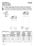
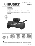
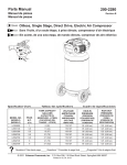
HP Modular Cooling System G2
Installation Overview
Safety information
The HP Modular Cooling System G2 is tested to the maximum
pressure (PS) of 8 bar (116 PSI) without fluid trapped inside by
closed, external valves.
If valves are installed on the external pipe work that could potentially
trap fluid inside the MCS unit, special precautions must be taken. In
order to prevent severe plumbing failure due to extreme pressure,
use an expansion tank with a preinstalled safety valve in the
plumbing circuit connected to the unit.
MCS G2 kit contents
Optimum environment and site
preparation
CAUTION: Contaminated water might cause decreased
cooling capacity or disruption in service. The water
flowing into the MCS unit must meet the guidelines stated
in the HP Modular Cooling System G2 Site Preparation
Guide. The MCS warranty does not cover damage caused
by contaminated water.
IMPORTANT: Before you begin the installation process,
read the HP Modular Cooling System G2 Site Preparation
Guide.
Environmental requirements must be met to provide optimum
performance with minimum maintenance for your unit.
The HP Modular Cooling System G2 Site Preparation Guide
provides information about planning your unit configuration
efficiently and organizing your site location before delivery of your
MCS unit.
To locate the latest version of the HP Modular Cooling System G2
Site Preparation Guide:
1.
Go to the HP website
(http://www.hp.com/go/rackandpower).
2.
Select Rack and Rack Options.
3.
Select Modular Cooling System.
4.
Select Support and Documents.
5.
Select Manuals.
6.
Select and download the HP Modular Cooling System G2 Site
Preparation Guide.
•
HP MCS G2 unit installed on an HP 10000 G2 Series Rack (1)
•
Automatic Door Release kit (1)
•
Rear plate cover (1)
•
Condensation pump to facility hose (blue) (1)
•
Condensation pan to facility hose (clear)* (1)
•
Power cord, 4.5 m (14.8 ft), L6-20 to C19 (2)
•
Power cord, 4.5 m (14.8 ft), IEC-309 to C19 (2)
•
CAT5e cable, 7.62 m (25 ft) (1)
•
Serial cable* (1)
•
Access panel (1)
•
Bracket (2)
•
M6 trilobe flathead screw (2)
•
M6 flathead screw (2)
*This item might ship preinstalled on the MCS unit rather than in the
standard kit contents package.
Required tools
The following tools are required for installation:
•
Flat blade screwdriver
•
#2 Phillips screwdriver
•
Adjustable wrench
•
T-25 Torx driver
•
T-30 Torx driver
•
Bubble level
•
Cap wrench (included with your HP Hook-Up Kit)
•
Hose wrench (included with your HP Hook-Up Kit)
Installing the MCS unit
WARNING: The MCS unit and rack are shipped together
on a heavy duty shock pallet weighing approximately
1633 kg (3600 lb). HP recommends hiring professional
movers to move the heavy duty shock pallet, remove the
MCS unit and rack from the pallet, and move the MCS
unit and rack to the final location.
CAUTION: Contaminated water might cause decreased
cooling capacity or disruption in service. The water
flowing into the MCS unit must meet the guidelines stated
in the HP Modular Cooling System G2 Site Preparation
Guide. The MCS warranty does not cover damage caused
by contaminated water.
7.
Lower the unit by raising the two rear leveling feet on both the
MCS unit and the rack so that the MCS unit can move freely on
the remaining casters.
8.
Adjust the leveling feet to level the MCS unit and rack, using a
bubble level.
IMPORTANT: Before you begin the installation process,
read the HP Modular Cooling System G2 Site Preparation
Guide.
1.
Install the HP Hook-Up Kit.
2.
Read the unpacking instructions on the MCS packaging
material.
3.
Remove the MCS unit and rack from the pallet with four or
more people.
4.
Roll the MCS unit and rack to the final location.
NOTE: You only need to remove the caster plate (steps 4
through 6) if you are routing your hoses through the hole
in the raised floor.
5.
6.
IMPORTANT: Check both ball valves on the water hoses to
confirm that they are in the closed position before
attaching the hoses to the MCS unit. Water that leaks into
the unit can cause significant damage.
Loosen the jam nut, and then raise the unit by lowering the two
rear leveling feet on both the MCS unit and the rack until you
can remove the rear caster plate.
9.
Route the water hoses from the HP Hook-Up Kit through the
floor cut-out.
10.
Install each main hose to the MCS unit using the hose wrench.
Remove the rear caster plate.
11.
Cap the unused side of each T-fitting on the MCS unit using the
cap wrench.
14.
Plug the network cable into the RJ-45 connector on the power
inlet box.
12.
Route the two drain hoses to the drain collection system catch
basin.
15.
Plug the other end of the network cable to your network
connection.
a. Install and route the blue drain hose into either the
condensation return line or the gravity drain collection
system catch basin.
b. Route the preinstalled clear drain hose into the gravity
drain collection system catch basin.
c.
13.
Position the gravity drain collection system below the
condensation collection pan, allowing gravity to draw the
water out of the condensation collection pan and into the
gravity drain collection system basin.
Turn on the water by opening the four ball valves.
a. Open the ball valves at the facility water line connections.
b. Open the ball valves at the main hose connections.
IMPORTANT: Do not connect the power cords into a
power supply.
16.
Plug the primary power cord into the power connector on the
left.
WARNING: To reduce the risk of electric shock or
damage to the equipment:
•
Do not disable the power cord grounding plug. The
grounding plug is an important safety feature.
•
Plug the power cord into a grounded (earthed)
electrical outlet that is easily accessible at all times.
•
Unplug the power cord from the power supply to
disconnect power to the equipment.
•
Do not route the power cord where it can be walked
on or pinched by items placed against it. Pay
particular attention to the plug, electrical outlet, and
the point where the cord extends from the storage
system.
17.
If you are using a secondary power cord, plug it into the
power connector on the right.
Powering up and configuring
the unit
WARNING: To reduce the risk of electric shock or
damage to the equipment:
18.
19.
Guide the other ends of the power cords through the MCS unit,
and then plug them into an appropriate power source.
(Optional) Secure the two brackets to the MCS frame using two
M6 trilobe flathead screws.
20.
(Optional) Align the access panel with the two brackets.
21.
(Optional) Secure the access panel to the brackets on the MCS
frame using two M6 flathead screws.
•
Do not disable the power cord grounding plug. The
grounding plug is an important safety feature.
•
Plug the power cord into a grounded (earthed)
electrical outlet that is easily accessible at all times.
•
Unplug the power cord from the power supply to
disconnect power to the equipment.
•
Do not route the power cord where it can be walked
on or pinched by items placed against it. Pay
particular attention to the plug, electrical outlet, and
the point where the cord extends from the storage
system.
1.
Plug the power cords into an appropriate power source.
2.
Connect the network cable to your network infrastructure.
NOTE: If you have a DHCP server, you can change the IP
address through the web interface instead of through the
serial port. For more information, refer to "Configuring the
IP address through the web interface (on page 8)."
3.
Using the serial cable provided, connect a PC with a serial
port or an asynchronous terminal to the serial communication
port on the management module.
4.
Access the management module through a terminal emulation
program, such as HyperTerminal or Minicom.
5.
Confirm that you have set the following parameters to access a
terminal emulation program:
6.
o
Bits per second: 9600
o
Data bits: 8
o
Parity: none
o
Stop bits: 1
o
Flow control: none
Log in to the HP Modular Cooling System Configuration Utility.
a. In the login field, enter the user name. The default user
name is Admin.
Installation is complete.
b. In the password field, enter the password. The default
password is Admin. The Main Menu screen appears.
7.
a. From the Main Menu screen, enter 1 Network
Configuration. The Menu Network Configuration
screen appears.
Enter the product ID and serial number. The product ID and 10digit serial number are located on a label inside the rear MCS
unit door.
b. Enter 1 IP Configuration. The IP Configuration screen
appears.
a. From the Main Menu screen, enter 3 Factory Default.
The Default Product Identification screen appears.
c.
d. Enter 1 IP Address, and then enter the new IP address.
b. To set the product ID, enter 2 Product ID MCS.
c.
e. Enter 2 IP Subnet mask, and then enter the IP subnet
mask.
To set the serial number, enter 3 Serial Number MCS.
d. To return to the Main Menu screen, press Esc.
8.
Access the HP Modular Cooling System Configuration Utility.
To disable DHCP, enter 4 Enable/Disable DHCP.
f.
9.
Enter 3 IP Def. Router, and then enter the gateway.
Activate the values.
a. Return to the Main Menu Network Configuration screen.
b. Enter 4 Activate Actual Values.
c.
10.
13.
Click Setup>Accounts, and then change the default Web
Admin and Web User passwords.
14.
Click Save Settings.
15.
(Optional, but recommended) Click
Setup>Management>Remote Access, select SSL Enable.
16.
(Optional) Enter an SSL key.
17.
Click Save Settings.
18.
To set up your trap receivers, click Setup>Management>Trap
Receivers.
19.
Click Save Settings.
To reboot, enter y at the prompt. You must reboot to
activate the IP settings, product ID, and serial number
values.
Access the Management module through the web interface.
a. Launch a supported browser. The browser window
appears.
b. In the Address field (Microsoft® Internet Explorer) or the
Location field (Firefox Mozilla), enter
http://ipaddress (where ipaddress is the IP
address of the management module). The login screen
appears.
11.
Log in through the web interface.
a. Enter the user name in the User Name field. The default
user name is Admin.
b. Enter the password in the Password field. The default
password is Admin.
c.
12.
Click Sign In.
Verify that the water source is available and turned on by
viewing the Water Flow status in the Overview menu.
20.
(Optional, but recommended) To set up your SNMP managers,
click Setup>Management>SNMP Managers.
4.
Click Setup>Network.
a. Select the radio button to disable DHCP (enabled is the
default setting).
b. Click Save Settings.
c.
Change the IP address in the IP Address field of the
management module.
d. Change the network mask of the management module.
e. Change the default gateway of the management module.
f.
Click Save Settings.
g. Log in to the new IP address.
21.
Click Save Settings.
For more information on adjusting the management module settings
through the web interface, see the HP Modular Cooling System G2
Web Interface User Guide located on the Documentation CD
shipped with this product.
Configuring the IP address through
the web interface
1.
View the IP address received from DHCP on the operator
display.
2.
Access the Management module through the web interface.
5.
Verify that the water source is available and turned on by
viewing the Water Flow status in the Overview menu.
6.
Click Setup>Accounts, and then change the default Web
Admin and Web User passwords.
7.
Click Save Settings.
8.
(Optional, but recommended) Click
Setup>Management>Remote Access, select SSL Enable.
a. Launch a supported browser. The browser window
appears.
b. In the Address field (Microsoft® Internet Explorer) or the
Location field (Firefox Mozilla), enter
http://ipaddress (where ipaddress is the IP
address of the management module). The login screen
appears.
3.
Log in through the web interface.
a. Enter the user name in the User Name field. The default
user name is Admin.
b. Enter the password in the Password field. The default
password is Admin.
c.
Click Sign In.
9.
(Optional) Enter an SSL key.
Automatic Door Release Kit
To view the HP Automatic Door Release hardware installation
instructions, see the documentation that shipped with that kit.
To enable the automatic door release functionality:
10.
Click Save Settings.
11.
To set up your trap receivers, click Setup>Management>Trap
Receivers.
12.
Click Save Settings.
13.
(Optional, but recommended) To set up your SNMP managers,
click Setup>Management>SNMP Managers.
14.
Click Save Settings.
For more information on adjusting the management module settings
through the web interface, see the HP Modular Cooling System G2
Web Interface User Guide located on the Documentation CD
included with this product.
1.
Click Setup>Advanced.
2.
Select the Enable button at the bottom of the screen.
Legal notices
© Copyright 2007 Hewlett-Packard Development Company, L.P.
The information contained herein is subject to change without notice. The only warranties for HP products and services are set forth in the express
warranty statements accompanying such products and services. Nothing herein should be construed as constituting an additional warranty.
HP shall not be liable for technical or editorial errors or omissions contained herein.
Microsoft and Windows are U.S. registered trademarks of Microsoft Corporation.
Part Number 463068-001
December 2007