1
HP Mid-Weight Slide Kit
(5069-6371)
Installation Instructions
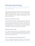
Required tools
About this device
The HP Mid-Weight Slide Kit (5069-6371) enables you to install HP
2U, 3U, 4U, and 5U servers into HP round-hole, square-hole,
threaded-hole, and early HP racks.
Kit contents
If any of the following items are missing or damaged, contact your
HP authorized reseller. The following hardware pieces are included
in this kit.
Quantity
Description
1
Cable management arm (J1539-63003)
2
Mid-weight inner slides (J1539-63001)
2
The following tools are required for installation:
•
T-25 Torx driver
•
Phillips screwdriver
•
Flathead screwdriver
•
M10 socket
•
Mid-weight slide-mounting alignment tool (included with this kit)
WARNING: To reduce the risk of personal injury or
damage to the equipment, be sure that:
Mid-weight outer slide assemblies (J153963002)
Hook-and-loop straps (1400-2030)
1
Mid-weight slide-mounting alignment tool
(5185-6098)
Hardware kit contents
Picture
•
The stabilizing feet are attached to the rack if it is a
single-rack installation.
•
The racks are coupled together in multiple-rack
installations.
•
Only one component is extended at a time. A rack
may become unstable if more than one component is
extended for any reason.
2
M5 x 30-mm screw (0515-2992)
1
M5 x 10-mm screw (5021-2991)
2
M5 x 16-mm screw (0515-3019)
•
4
M4 x 8-mm screw (0515-2478)
Installing the mid-weight slides in a rack
2
M5 barrel nut (5065-7210)
1.
Install the mid-weight inner slides ("Installing the mid-weight
inner slides" on page 1).
1
Tie-down bracket (5069-6357)
2.
Mark your rack columns using the mid-weight slide-mounting
alignment tool ("Marking your rack columns using the midweight slide-mounting alignment tool" on page 1).
3.
Follow the appropriate installation procedure for your
rack type:
Description
4
M5 x 16-mm screw (0515-3019)
2
M6 flathead screw (5185-6036)
2
Front bracket (5184-2312)
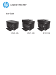
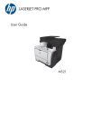
Marking your rack columns using the mid-weight
slide-mounting alignment tool
1.
Using the height of the mid-weight inner slides, mark both sides
of the mid-weight slide-mounting alignment tool.
2.
Using the marked mid-weight slide-mounting alignment tool,
mark the front and rear columns of the rack.
Perform one of the following:
•
Install the mid-weight slides in a rack ("Installing the mid-weight
slides in a rack" on page 1).
-or-
Picture
4.
Ship a rack with an integrated server ("Shipping a rack with an
integrated server" on page 3).
o
Installing the mid-weight slides in round-hole or square-hole
racks (on page 2)
o
Installing the mid-weight slides in threaded-hole racks
(on page 2)
o
Installing the mid-weight slides in early HP racks
o
(on page 2)
(Optional) Adjust the mid-weight outer slide assemblies
("(Optional) Adjusting the mid-weight outer slide assemblies"
on page 3).
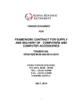
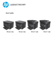
Installing the mid-weight inner slides
1.
Part Number 416755-003
March 2008 (Third Edition)
The full weight of the rack rests on the leveling feet.
Mid-weight slides overview
The optional hardware kit is required to install the mid-weight slide
kit into early HP racks.
The information contained herein is subject to change without notice. The
only warranties for HP products and services are set forth in the express
warranty statements accompanying such products and services. Nothing
herein should be construed as constituting an additional warranty. HP shall
not be liable for technical or editorial errors or omissions contained herein.
The leveling feet are extended to the floor.
•
Description
Optional hardware kit contents (J1539-63004)
© Copyright 2006, 2008 Hewlett-Packard Development Company, L.P.
•
Quantity
Quantity
Slide the mid-weight inner slides toward the rear of the server
until they lock into place.
Rack warning
Picture
2
2.
Align the mid-weight inner slide holes with the tabs on
the server.
Item
Description
1
Mark for HP 5U servers
2
Mark for HP 4U servers
3
Mark for HP 2U and HP 3U servers
HP Mid-Weight Slide Kit
(5069-6371)
Installation Instructions
Required tools
About this device
The HP Mid-Weight Slide Kit (5069-6371) enables you to install HP
2U, 3U, 4U, and 5U servers into HP round-hole, square-hole,
threaded-hole, and early HP racks.
Kit contents
If any of the following items are missing or damaged, contact your
HP authorized reseller. The following hardware pieces are included
in this kit.
Quantity
Description
1
Cable management arm (J1539-63003)
2
Mid-weight inner slides (J1539-63001)
2
The following tools are required for installation:
•
T-25 Torx driver
•
Phillips screwdriver
•
Flathead screwdriver
•
M10 socket
•
Mid-weight slide-mounting alignment tool (included with this kit)
WARNING: To reduce the risk of personal injury or
damage to the equipment, be sure that:
Mid-weight outer slide assemblies (J153963002)
Hook-and-loop straps (1400-2030)
1
Mid-weight slide-mounting alignment tool
(5185-6098)
Hardware kit contents
Picture
416755- 003
•
The stabilizing feet are attached to the rack if it is a
single-rack installation.
•
The racks are coupled together in multiple-rack
installations.
•
Only one component is extended at a time. A rack
may become unstable if more than one component is
extended for any reason.
2
M5 x 30-mm screw (0515-2992)
1
M5 x 10-mm screw (5021-2991)
2
M5 x 16-mm screw (0515-3019)
•
4
M4 x 8-mm screw (0515-2478)
Installing the mid-weight slides in a rack
2
M5 barrel nut (5065-7210)
1.
Install the mid-weight inner slides ("Installing the mid-weight
inner slides" on page 1).
1
Tie-down bracket (5069-6357)
2.
Mark your rack columns using the mid-weight slide-mounting
alignment tool ("Marking your rack columns using the midweight slide-mounting alignment tool" on page 1).
3.
Follow the appropriate installation procedure for your
rack type:
Description
4
M5 x 16-mm screw (0515-3019)
2
M6 flathead screw (5185-6036)
2
Front bracket (5184-2312)
Marking your rack columns using the mid-weight
slide-mounting alignment tool
1.
Using the height of the mid-weight inner slides, mark both sides
of the mid-weight slide-mounting alignment tool.
2.
Using the marked mid-weight slide-mounting alignment tool,
mark the front and rear columns of the rack.
Perform one of the following:
•
Install the mid-weight slides in a rack ("Installing the mid-weight
slides in a rack" on page 1).
-or-
Picture
4.
Ship a rack with an integrated server ("Shipping a rack with an
integrated server" on page 3).
o
Installing the mid-weight slides in round-hole or square-hole
racks (on page 2)
o
Installing the mid-weight slides in threaded-hole racks
(on page 2)
o
Installing the mid-weight slides in early HP racks
o
(on page 2)
(Optional) Adjust the mid-weight outer slide assemblies
("(Optional) Adjusting the mid-weight outer slide assemblies"
on page 3).
Installing the mid-weight inner slides
1.
Part Number 416755-003
March 2008 (Third Edition)
Printed in the US
The full weight of the rack rests on the leveling feet.
Mid-weight slides overview
The optional hardware kit is required to install the mid-weight slide
kit into early HP racks.
The information contained herein is subject to change without notice. The
only warranties for HP products and services are set forth in the express
warranty statements accompanying such products and services. Nothing
herein should be construed as constituting an additional warranty. HP shall
not be liable for technical or editorial errors or omissions contained herein.
The leveling feet are extended to the floor.
•
Description
Optional hardware kit contents (J1539-63004)
© Copyright 2006, 2008 Hewlett-Packard Development Company, L.P.
•
Quantity
Quantity
Slide the mid-weight inner slides toward the rear of the server
until they lock into place.
Rack warning
Picture
2
2.
Align the mid-weight inner slide holes with the tabs on
the server.
Item
Description
1
Mark for HP 5U servers
2
Mark for HP 4U servers
3
Mark for HP 2U and HP 3U servers
Installing the mid-weight slides in round-hole or
square-hole racks
3.
Remove the three pins from the front and rear of the mid-weight
outer slide assemblies.
3.
Remove the front and rear brackets from the mid-weight outer
slide assemblies, and save the four nuts.
Install the mid-weight inner slides ("Installing the mid-weight
inner slides" on page 1).
2.
Mark your rack columns using the mid-weight slide-mounting
alignment tool ("Marking your rack columns using the midweight slide-mounting alignment tool" on page 1).
3.
Install the mid-weight outer slide assemblies by aligning the
center pin of the mid-weight outer slide assemblies with the
markings on front and rear of the rack columns.
WARNING: Two people are needed to align and install
the server properly. Do not install the server with the midweight inner slides extended.
NOTE: Screws for threaded-hole racks are not supplied in
the kit. These screws are supplied by your rack
manufacturer.
4.
4.
Proceed to "Sliding the server into the mid-weight outer slide
assemblies (on page 2)."
Sliding the server into the mid-weight outer
slide assemblies
NOTE: If the rear slide brackets must adjust to shallower
or deeper third-party columns, see "(Optional) Adjusting
the mid-weight outer slide assemblies (on page 3)."
1.
7.
4.
1.
Slide the server into the mid-weight outer slide assemblies.
2.
Connect the cables to the server.
3.
Install and secure the cable management arm to the mid-weight
outer slide assemblies.
Align (1) the top hole of the front brackets with the markings on
the front of the rack columns. Secure the front brackets to the
rack using M5 x 16-mm screws (2).
Using the screws supplied by your rack manufacturer, install
the mid-weight outer slide assemblies by aligning the center
hole of the mid-weight outer slide assemblies with the marking
on the front and rear of the rack columns.
Proceed to "Sliding the server into the mid-weight outer slide
assemblies (on page 2)."
Installing the mid-weight slides in threaded-hole
racks
NOTE: If the rear slide brackets must adjust to shallower
or deeper third-party columns, see "(Optional) Adjusting
the mid-weight outer slide assemblies (on page 3)."
1.
Install the mid-weight inner slides ("Installing the mid-weight
inner slides" on page 1).
5.
2.
Mark your rack columns using the mid-weight side-mounting
alignment tool ("Marking your rack columns using the midweight slide-mounting alignment tool" on page 1).
Installing the mid-weight slides in early HP racks
Proceed to "Sliding the server into the mid-weight outer slide
assemblies (on page 2)."
1.
Install the mid-weight inner slides ("Installing the mid-weight
inner slides" on page 1).
2.
Mark your rack columns using the mid-weight slide-mounting
alignment tool ("Marking your rack columns using the midweight slide-mounting alignment tool" on page 1).
5.
Transfer the markings from the front of the rack columns to the
sides of the rack columns, and install the mid-weight outer slide
assemblies by aligning the threaded side studs with the
markings on the rack columns.
6.
Secure the front of the outer slide assemblies to the rack
columns using the nuts from step 3. Secure the rear of the midweight outer slide assemblies to the rack columns using M6
flathead screws and the nuts from step 3.
4.
Extending the cable management arm, slide the server
forward.
(Optional) Adjusting the mid-weight outer slide
assemblies
Shipping a rack with an integrated server
NOTE: If the rear slide brackets must adjust to shallower
or deeper third-party columns, see "(Optional) Adjusting
the mid-weight outer slide assemblies (on page 3)."
NOTE: These steps apply only if the adjustment of the
outer slide assemblies are necessary to fit shallower or
deeper third-party racks.
1.
Remove the slide-locking clips from the outer slide assemblies.
c.
Using two M4 x 8-mm screws, secure the mid-weight inner
slides to an HP 4U server.
NOTE: All M4 screws must be torqued to 2.4 Nm (22 lb).
1.
Install the mid-weight inner slides, and secure them to the
server, using the required number of M4 x 8-mm screws.
a. Using two M4 x 8-mm screws, secure the mid-weight inner
slides to an HP 2U server.
5.
Route the cables through the cable management arm.
d. Using four M4 x 8-mm screws, secure the mid-weight inner
slides to an HP 5U server.
2.
Adjust the slide assemblies for your rack, and then install the
slide-locking clips.
b. Using two M4 x 8-mm screws, secure the mid-weight inner
slides to an HP 3U server.
6.
Install hook-and-loop straps, as needed, to secure the cables.
2.
Using the height of the mid-weight inner slides, mark both sides
of the mid-weight slide-mounting alignment tool.
3.
Using the marked mid-weight slide-mounting alignment tool,
mark the front and rear columns of the rack.
Item
Description
1
Mark for HP 5U servers
2
Mark for HP 4U servers
3
Mark for HP 2U and HP 3U servers
4.
6.
Install the mid-weight outer slide assemblies by aligning the
center pin of the mid-weight outer slide assemblies with the
markings on the front and rear of the rack columns.
7.
Screw the M5 x 30-mm screws to the mid-weight outer slide
assemblies to secure it to the rack.
10.
Install and secure the cable management arm to the mid-weight
outer slide assemblies.
11.
Extending the cable management arm, slide the server
forward.
13.
Install hook-and-loop straps, as needed, to secure the cables.
NOTE: The yellow plastic shipping tie is not included in
the kit (0684-0860 or equivalent).
14.
Install a yellow plastic shipping tie.
WARNING: Two people are needed to align and install
the server properly. Do not install the server with the midweight inner slides extended.
Remove the top pin from the mid-weight outer slide assemblies.
8.
Slide the server into the mid-weight outer slide assemblies.
12.
Route the cables through the cable management arm.
NOTE: All M5 screws must be torqued to 6.2 Nm (55 lb).
15.
NOTE: All M5 screws must be torqued to 6.2 Nm (55 lb).
5.
Install the M5 barrel nuts on the rack columns.
9.
Connect the cables to the server.
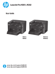
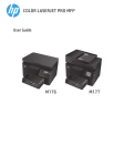
Use the M5 x 16-mm screws to install and secure the tie-down
bracket to the mid-weight right outer slide assembly. If you
have a square-hole rack, insert the M5 x 10-mm screw in hole
(1). If you have a round-hole rack, insert the M5 x 10-mm
screw in hole (2).
3.
Using the marked mid-weight slide-mounting alignment tool,
mark the front and rear columns of the rack.
Item
Description
1
Mark for HP 5U servers
2
Mark for HP 4U servers
3
Mark for HP 2U and HP 3U servers
4.
6.
Install the mid-weight outer slide assemblies by aligning the
center pin of the mid-weight outer slide assemblies with the
markings on the front and rear of the rack columns.
7.
Screw the M5 x 30-mm screws to the mid-weight outer slide
assemblies to secure it to the rack.
10.
Install and secure the cable management arm to the mid-weight
outer slide assemblies.
11.
Extending the cable management arm, slide the server
forward.
13.
Install hook-and-loop straps, as needed, to secure the cables.
NOTE: The yellow plastic shipping tie is not included in
the kit (0684-0860 or equivalent).
14.
Install a yellow plastic shipping tie.
WARNING: Two people are needed to align and install
the server properly. Do not install the server with the midweight inner slides extended.
Remove the top pin from the mid-weight outer slide assemblies.
8.
Slide the server into the mid-weight outer slide assemblies.
12.
Route the cables through the cable management arm.
NOTE: All M5 screws must be torqued to 6.2 Nm (55 lb).
15.
NOTE: All M5 screws must be torqued to 6.2 Nm (55 lb).
5.
Install the M5 barrel nuts on the rack columns.
9.
Connect the cables to the server.
Use the M5 x 16-mm screws to install and secure the tie-down
bracket to the mid-weight right outer slide assembly. If you
have a square-hole rack, insert the M5 x 10-mm screw in hole
(1). If you have a round-hole rack, insert the M5 x 10-mm
screw in hole (2).