1
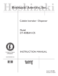
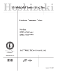
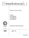
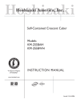
Hoshizaki
Hoshizaki America, Inc.
Self-Contained Flaker
Model
F-330BAH(-C)
“A Superior Degree
of Reliability”
INSTRUCTION MANUAL
www.hoshizaki.com
®
Issued: 5-4-2007
Revised: 9-5-2007
IMPORTANT
Only qualified service technicians should attempt to install, service, or maintain
this icemaker. No installation, service, or maintenance should be undertaken
until the technician has thoroughly read this Instruction Manual. Likewise, the
owner/manager should not proceed to operate the icemaker until the installer
has instructed them on its proper operation. Failure to install, operate, and
maintain the equipment in accordance with this manual may adversely affect
safety, performance, and warranty coverage.
HOSHIZAKI provides this manual primarily to assist qualified service technicians in the
installation, maintenance, and service of the icemaker.
Should the reader have any questions or concerns which have not been satisfactorily
addressed, please call, write, or send an e-mail message to the HOSHIZAKI Technical
Support Department for assistance.
HOSHIZAKI AMERICA, INC.
618 Highway 74 South
Peachtree City, GA 30269
Attn: HOSHIZAKI Technical Support Department
Phone: 1-800-233-1940 Technical Service
(770) 487-2331
Fax: 1-800-843-1056
(770) 487-3360
E-mail: [email protected]
Web Site: www.hoshizaki.com
NOTE: To expedite assistance, all correspondence/communication MUST include the following information:
• Model Number
• Serial Number
• Complete and detailed explanation of the problem
• Please review this manual. It should be read carefully before the icemaker is installed
and operated. Only qualified service technicians should install, service, and maintain the
icemaker. This manual should be made available to the technician prior to installation,
maintenance, or service.
• Keep this manual with the icemaker for later reference.
CONTENTS
I. Specifications...................................................................................................................... 4
A. Nameplate Rating.......................................................................................................... 4
B. Dimensions/Connections............................................................................................... 5
II. Installation and Operating Instructions............................................................................... 6
A. Checks Before Installation............................................................................................. 6
B. How to Remove Panels ................................................................................................ 6
C. Location......................................................................................................................... 7
D. Setup............................................................................................................................. 7
E. Electrical Connection..................................................................................................... 7
F. Water Supply and Drain Connections............................................................................ 7
G. Final Checklist .............................................................................................................. 9
H. Startup......................................................................................................................... 10
III. Cleaning and Maintenance.............................................................................................. 11
A. Cleaning and Sanitizing Instructions............................................................................ 11
1. Cleaning Solution................................................................................................... 11
2. Cleaning Procedure................................................................................................ 11
3. Sanitizing Solution.................................................................................................. 13
4. Sanitizing Procedure - Initial................................................................................... 13
5. Sanitizing Procedure - Final................................................................................... 13
B. Maintenance ............................................................................................................... 15
C. Preparing the Icemaker for Long Storage .................................................................. 16
I. Specifications
A. Nameplate Rating
1. F-330BAH, F-330BAH-C
HOSHIZAKI ICE MAKER
MODEL NUMBER
SERIAL NUMBER
AC SUPPLY VOLTAGE
AMPERES
DESIGN PRESSURE
REFRIGERANT
F-330BAH
115/60/1
6.7 AMPS
HI-470PSI LO-230PSI
404A 7.1 OZ.
MOTOR-COMPRESSOR THERMALLY PROTECTED,
NOT INTENDED FOR OUTDOOR USE!
Hoshizaki America, Inc.
Peachtree City, GA
www.hoshizaki.com
LISTED
ICE MAKER
946Z
Note: Only the "MODEL NUMBER" is replaced for F-330BAH-C.
See the nameplate for electrical and refrigeration specifications. This nameplate is located
on the rear panel.
We reserve the right to make changes in specifications and design without prior notice.
B. Dimensions/Connections
Unit = inches (mm)
1. F-330BAH, F-330BAH-C
II. Installation and Operating Instructions
A. Checks Before Installation
IMPORTANT
1. Install in accordance with all applicable national, state, and local regulations.
2. Remove shipping carton, tape, and packing. If any are left in the icemaker, it
will not work properly.
3. Ensure all components, fasteners, and thumbscrews are securely in place
after installation.
• Remove the top panel and front panel to prevent damage when installing the
icemaker.
• Remove the package containing the accessories.
• Remove the protective plastic film from the panels. If the icemaker is exposed
to the sun or to heat, remove the film after the icemaker cools.
• Check that the refrigerant lines do not rub or touch lines or other surfaces, and
that the fan blade turns freely.
• Check that the compressor is snug on all mounting pads.
• See the nameplate on the rear panel, and check that your voltage supplied
corresponds with the voltage specified on the nameplate.
B. How to Remove Panels
See Fig. 1
• Front Panel: Remove the screw. Lift up
and towards you.
Screw
Screw
• Top Panel: Open the door. Remove the
screws. Lift up at the front slightly, push
rearward, and lift off.
Door
Front Panel
Fig. 1
Screw
Top Panel
C. Location
CAUTION
This icemaker is not intended for outdoor use. Normal operating ambient
temperature should be within +45°F to +100°F (+7°C to +38°C); Normal
operating water temperature should be within +45°F to +90°F (+7°C to +32°C).
Operation of the icemaker, for extended periods, outside of these normal
temperature ranges may affect icemaker performance.
For best operating results:
• Icemaker should not be located next to ovens, grills or other high heat producing
equipment.
• Location should provide a firm and level foundation for the equipment.
• Allow 24" (61 cm) clearance at top to allow for removal of the auger and for ease of
maintenance and/or service should they be required.
D. Setup
1) Attach the four adjustable legs provided to the bottom of the icemaker.
2) Position the icemaker in the selected permanent location.
3) Level the icemaker from side-to-side and front-to-rear by adjusting the legs.
E. Electrical Connection
WARNING
The GREEN ground wire in the factory-installed power cord is connected
to a screw on the bracket where the cord enters the machine. If it becomes
necessary to remove or replace the power cord, be sure to connect the power
cord's ground wire to this screw upon reattachment.
• Electrical connections must be installed in accordance with applicable national, state
and local regulations.
• The unit requires an independent power supply. See the nameplate for proper voltage
and breaker/fuse size.
• Usually an electrical permit and services of a licensed electrician are required.
F. Water Supply and Drain Connections
• Water supply inlet is 1/2" female pipe thread (FPT).
• A water supply line shut-off valve and drain valve must be installed. A minimum of
3/8" OD copper tubing is recommended for the water supply lines.
• Water supply pressure should be a minimum of 10 PSIG and a maximum of 113 PSIG.
If the pressure exceeds 113 PSIG, the use of a pressure reducing valve is required.
• Drain outlet is 3/4" FPT.
• Drain line must have 1/4" fall per foot (2 cm per 1 m) on horizontal runs to get good
flow. A vented tee connection is also required for proper flow.
• Drain line should not be piped directly to the sewer system. An air gap of a minimum of
2 vertical inches (5 cm) should be between the end of the drain pipe from the unit and
the floor drain.
• This icemaker must be installed in accordance with applicable national, state, and local
regulations.
• A plumbing permit and services of a licensed plumber may be required in some areas.
Fig. 2
Water Supply Inlet
1/2" FPT
Shut-Off
Valve
Piping to
approved
drain.
Drain Outlet
3/4" FPT
Drain Valve
Two-inch
(5 cm) air gap
Floor
Drain
G. Final Checklist
1) Is the icemaker level?
2) Is the icemaker in a site where the ambient temperature is within +45°F to +100°F
(+7°C to +38°C) and the water temperature within +45°F to +90°F (+7°C to +32°C) all
year around?
3) Is there at least 24" (61 cm) clearance at top for maintenance or service?
4) Have the shipping carton and all tape and packing been removed from the icemaker?
5) Are all components, fasteners, and thumbscrews securely in place?
6) Have all electrical and piping connections been made?
7) Has the power supply voltage been checked or tested against the nameplate rating?
And has a proper ground been installed to the icemaker?
8) Are the water supply line shut-off valve and drain valve installed? Has the water
supply pressure been checked to ensure a minimum of 10 PSIG and a maximum of
113 PSIG?
Note: The icemaker may stop running when the water supply is OFF, or if the pressure
is below 10 PSIG. When the proper water pressure is reached, the icemaker will
automatically start running again.
9) Are the compressor hold-down bolts snug? Have the refrigerant lines been checked to
make sure they do not rub or touch other lines or surfaces?
10) Has the bin control switch been checked for correct operation? Move the actuator
located on the inside of the bin top panel. The compressor should stop within
90 seconds, and the gear motor within 150 seconds.
11) Has the end user been given the instruction manual, and instructed on how to operate
the icemaker and the importance of the recommended periodic maintenance?
12) Has the end user been given the name and telephone number of an authorized service
agent?
13) Has the warranty tag been filled out and
forwarded to the factory for warranty
registration?
Spout
14) Have the safety switch brackets moved
out of location during shipping? Make sure
they are in position as illustrated in Fig. 3.
Safety Bracket (A)
15) Has the safety switch been checked for
correct operation? Activate the safety
switch. The ice machine should shut down
immediately. Turn the ice machine off, then
back on, to reset.
Safety Switch
Fig. 3
Safety Bracket (B)
H. Startup
CAUTION
1. All parts are factory-adjusted. Improper adjustments may result in failure.
2. If the unit is turned off, wait for at least 3 minutes before restarting the
icemaker to prevent damage to the compressor.
1) Clean the storage bin.
2) Open the water supply line shut-off valve.
3) Make sure the power switch on the control box is in the "OFF" position. Plug the unit
into the electrical outlet.
4) Move the flush switch to the "ICE" position and move the power switch to the
"ON" position to start the automatic icemaking process.
5) Replace the panels in their correct positions.
10
III. Cleaning and Maintenance
A. Cleaning and Sanitizing Instructions
IMPORTANT
Ensure all components, fasteners, and thumbscrews are securely in place after
any maintenance or cleaning is done to the equipment.
WARNING
1. HOSHIZAKI recommends cleaning this unit at least twice a year. More
frequent cleaning, however, may be required in some existing water
conditions.
2. To prevent injury to individuals and damage to the icemaker, do not use
ammonia type cleaners.
3. Carefully follow any instructions provided with the bottles of cleaning and
sanitizing solution.
4. Always wear liquid-proof gloves to prevent the cleaning and sanitizing
solutions from coming into contact with skin.
5. Never run the icemaker when the reservoir is empty.
6. After cleaning, do not use ice made from the cleaning and sanitizing
solutions. Be careful not to leave any solution in the storage bin.
1. Cleaning Solution
Dilute 4.8 fl. oz. (142 ml) of recommended cleaner Hoshizaki "Scale Away" or
"LIME‑A‑WAY" (Economics Laboratory, Inc.) with 0.8 gallons (3 l) of warm water. This is
a minimum amount. Make more solution if necessary.
IMPORTANT
For safety and maximum effectiveness, use the solution immediately after
dilution.
2. Cleaning Procedure
1) Close the water supply line shut-off valve.
2) Remove the panels. Move the power switch to the "OFF" position and unplug the unit
from the electrical outlet.
3) Remove all ice from the storage bin.
4) Plug the unit back in. Move the flush switch to the "FLUSH" position and move the
power switch to the "ON" position to drain out the water from the icemaker.
5) After the water has drained, move the power switch to the "OFF" position. Unplug the
unit.
11
6) Lift up the top insulation and unsnap the
bin control assembly. Lift the assembly up
through the insulation and set it aside. See
Fig. 4.
Bin Control
Assembly
7) Remove the top insulation.
8) Remove the thumbscrews attaching spout
(B) to the bin, then remove spout (B). See
Fig. 5.
Top Insulation
9) Remove the thumbscrews attaching
spout (A) and safety bracket (A) to the
evaporator assembly, then remove
spout (A) and safety bracket (A). See
Fig. 5.
10) Pour the cleaning solution over the
extruding head until the evaporator
assembly and the reservoir are full and the
solution starts to overflow into the drain
pan.
Note: If there is excess scale on the
extruding head, fill the evaporator
assembly and reservoir as described
above, then use a clamp on the
reservoir hose between the reservoir
and evaporator assembly to block
flow. Pour additional cleaning fluid
over the extruding head until the
evaporator assembly is completely
full.
Fig. 4
Thumbscrew
Spout
Packing (A)
Safety Bracket (A)
Spout (A)
Extruding
Head
Evaporator
Assembly
Cylinder
Packing
Spout (B)
Thumbscrew
11) Allow the icemaker to sit for about
10 minutes before operation. If you placed
a clamp on the reservoir hose in step 10,
remove it before operation.
Fig. 5
12) Replace all parts in their correct positions. Make sure safety bracket (A) is in position as
illustrated in Fig. 7.
13) Plug the unit back in. Move the flush switch to the "ICE" position and move the power
switch to the "ON" position. Replace the panels in their correct positions and allow the
unit to make ice using the solution until it stops automatically.
Note: This unit is designed to start operating when the water reservoir is full.
14) Remove the front panel.
15) Move the flush switch to the "FLUSH" position to drain the remainder of the solution.
16) After the solution has drained, move the flush switch to the "ICE" position.
17) Replace the front panel in its correct position.
18) Open the water supply line shut-off valve to supply water to the reservoir.
12
19) When the gear motor starts, remove the front panel and move the flush switch to the
"FLUSH" position to drain out the water from the icemaker.
20) After the water has drained, move the power switch to the "OFF" position and unplug
the unit.
Note: If you do not sanitize the icemaker, leave the unit plugged in with the power
switch in the "ON" position and go to step 18 in "5. Sanitizing Procedure - Final."
3. Sanitizing Solution
Dilute 2.5 fl. oz. (74 ml or 5 tbs) of a 5.25% sodium hypochlorite solution (chlorine
bleach) with 5 gallons (19 l) of warm water.
IMPORTANT
For safety and maximum effectiveness, use the solution immediately after
dilution.
4. Sanitizing Procedure - Initial
1) Close the water supply line shut-off valve.
2) Remove the top panel. Remove the bin control assembly from the top insulation and
set it aside. Remove the top insulation.
3) Remove the thumbscrews attaching spout (B) to the bin, then remove spout (B).
4) Remove the thumbscrews attaching spout (A) and safety bracket (A) to the evaporator
assembly, then remove spout (A) and safety bracket (A). Remove spout packing (A)
and the cylinder packing. See Fig. 5.
5) Pour the sanitizing solution over the extruding head until the evaporator assembly and
the reservoir are filled and the solution starts to overflow into the drain pan.
6) Lift up slightly on the clip securing the bin control switch to
the paddle assembly and slide the switch out. See Fig. 6.
7) Soak the spouts, packings and paddle assembly in
.25 gallons (1 l) of sanitizing solution for 10 minutes then
wipe them down.
Clip
8) Rinse the parts thoroughly, then replace all parts in their
correct positions.
9) Plug the unit back in. Move the flush switch to the "ICE"
position and move the power switch to the "ON" position.
Replace the panels in their correct positions and allow
the unit to make ice using the solution until it stops
automatically.
Bin Control
Switch
Paddle
Assembly
Fig. 6
5. Sanitizing Procedure - Final
1) Remove the front panel.
2) Move the flush switch to the "FLUSH" position to drain the remainder of the solution.
3) After the solution has drained, move the power switch to the "OFF" position and unplug
the unit.
13
4) Remove the top panel.
5) Remove the bin control assembly from the top insulation and set it aside. Remove the
top insulation.
6) Remove the thumbscrews attaching spout (B) to the bin, then remove spout (B).
7) Remove the thumbscrews attaching spout (A) and safety bracket (A) to the evaporator
assembly, then remove spout (A) and safety bracket (A).
8) Pour the sanitizing solution over the extruding head until the evaporator assembly and
the reservoir are filled and the solution starts to overflow into the drain pan.
9) Allow the icemaker to sit for about 10 minutes before operation.
10) Replace all parts in their correct positions. Make sure safety bracket (A) is in position as
illustrated in Fig. 7.
11) Plug the unit back in. Move the flush switch
to the "ICE" position and move the power
switch to the "ON" position. Replace the
panels in their correct positions and allow
the unit to make ice using the solution until
it stops automatically.
Spout
Safety Bracket (A)
12) Remove the front panel.
13) Move the flush switch to the "FLUSH"
position to drain the remainder of the
solution.
Safety Bracket (B)
14) After the solution has drained, move the
flush switch to the "ICE" position.
Safety Switch
15) Replace the front panel in its correct position.
Fig. 7
16) Open the water supply line shut-off valve to supply water to the reservoir.
17) When the gear motor starts, remove the front panel and move the flush switch to the
"FLUSH" position to drain out the water from the icemaker.
18) After the water has drained, move the flush switch to the "ICE" position and allow the
icemaker to run. Replace the front panel in its correct position.
19) After 30 minutes, remove the front panel and move the power switch to the "OFF"
position. Unplug the unit.
20) Pour warm water into the storage bin to melt all ice, then clean the bin liner with the
solution.
21) Flush out any solution from the storage bin.
22) Plug the unit back in. Move the power switch to the "ON" position to start the automatic
icemaking process.
23) Replace the front panel in its correct position.
14
B. Maintenance
IMPORTANT
1. This icemaker must be maintained individually, referring to the instruction
manual and labels provided with the icemaker.
2. To achieve optimum icemaker performance, the following parts need periodic
inspection and maintenance:
Extruding Head and Upper Bearing
Housing and Lower Bearing
Evaporator Cylinder
Auger
Gear Motor
Mechanical Seal
These parts should be inspected at least once a year or every 10,000 hours of operation. Their service life, however, depends on water quality and
environment. More frequent inspection and maintenance are recommended
in bad or severe water conditions.
Replacement of the following consumable parts is recommended if wear
exceeds factory recommendations:
Upper Bearing
Lower Bearing
Mechanical Seal
Consult with your local distributor about inspection and maintenance
service. To obtain the name and phone number of your local distributor, call
Hoshizaki Technical Support at 1-800-233-1940 in the USA.
1. Stainless Steel Exterior
To prevent corrosion, wipe the exterior occasionally with a clean and soft cloth. Use a
damp cloth containing a neutral cleaner to wipe off oil or dirt build up.
2. Storage Bin and Scoop
• Wash your hands before removing ice. Use the plastic scoop provided (bin accessory).
• The storage bin is for ice use only. Do not store anything else in the bin.
• Keep the scoop clean. Clean using a neutral cleaner and rinse thoroughly.
• Clean the bin liner using a neutral cleaner. Rinse thoroughly after cleaning.
3. Air Filters
Plastic mesh air filters remove dirt or dust from the air, and keep the condenser from
getting clogged. As the filters get clogged, the icemaker’s performance will be reduced.
Check the filters at least twice a month. When clogged, use warm water and a neutral
cleaner to wash the filters.
4. Condenser
Check the condenser once a year, and clean if required by using a brush or vacuum
cleaner. More frequent cleaning may be required depending on the location of the
icemaker.
15
C. Preparing the Icemaker for Long Storage
CAUTION
When the icemaker is not used for two or three days under normal conditions, it
is sufficient to only move the power switch to the "OFF" position. When storing
the icemaker for extended time or in sub-freezing temperatures, turn the water
off and drain out all water from the water lines and remove the ice from the bin.
The bin should be cleaned and dried. Drain the icemaker water hoses using air
or carbon dioxide to prevent damage at sub-freezing temperatures.
1) Run the icemaker with the potable water supply line shut-off valve closed. Allow the unit
to make ice until it stops automatically.
2) Open the potable water supply line drain valve and blow the line out using compressed
air or carbon dioxide.
3) Remove the front panel and move the flush switch to the "FLUSH" position to drain out
the remaining water from the icemaker.
4) After the water has drained, move the power switch to the "OFF" position and unplug
the unit.
5) Replace the front panel in its correct position.
6) Close the potable water supply line drain valve.
7) Remove all ice from the storage bin and clean the bin.
16
HOSHIZAKI AMERICA, INC.
618 Hwy. 74 S., Peachtree City, GA 30269 USA TEL (770) 487-2331 FAX (770) 487-3360 www.hoshizaki.com 91A2SA10B
17