1
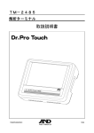
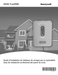
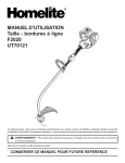
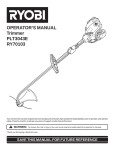
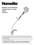
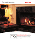
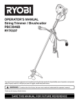
T87 Range Stops
INSTALLATION INSTRUCTIONS
APPLICATION
INSTALLATION
Use the 50010944-001 range stops with the T87K, N
thermostats to limit the minimum and maximum
temperature settings.
1.
The 50010944-001 contains two range stop scales and
two #2-28 x 3/8 phillips pan head screws.
3.
2.
Set the thermostat to a temperature setting in the
middle of the upper and lower range desired.
Remove the thermostat from its base (if already
attached).
On the back of the thermostat, align the range stop
with the holes on the back of the thermostat. See
Fig. 3.
HIGH LIMIT
SETTING
70
70
60
50
80
80
RANGE STOP
LOW LIMIT
SETTING
60
SCREW (2)
50
M13675
Fig. 1. Range stop and screws (Fahrenheit range).
HIGH LIMIT
SETTING
RANGE STOP
M13679
26
20
LOW LIMIT
SETTING
15
Fig. 3. Aligning range stop with thermostat.
4.
SCREW (2)
09
5.
Using the temperature markings on the range stop,
insert supplied screws into the minimum and/or
maximum range stop holes and tighten. Refer to
Tables 1 and 2 for range stop temperatures. See
Figs. 4 and 5.
Mount the thermostat onto its base and set desired
temperature. See Fig. 5.
M13676
Fig. 2. Range stop and screws (Celsius range).
69-1864EFS
T87 RANGE STOPS
Table 1. Low Limit Range Stop
64°
70
80
°F
60°
56° LOW
LIMIT
SETTING
60
FAHRENHEIT SCALE
50°
50
46°
42°
16.5°
20
26
15°
12° LOW
LIMIT
SETTING
15
10°
9°
09
CELSIUS SCALE
8°
5°
M13677
Fig. 4. Low range stop settings.
76° HIGH LIMIT
SETTING
70°
°C
42
4
44
5
46
6.5
48
8
50
9
52
10
54
11
56
12
58
13
60
14.5
62
15.5
64
16.5
66
17.5
68
19
70
20
72
21
74
22.5
76
23.5
78
24.5
80
26
80°
84°
Table 2. High Limit Range Stop
70
80
88°
FAHRENHEIT SCALE
23.5° HIGH LIMIT
SETTING
21° 19°
26
88
50
27°
28°
29°
°F
60
20
15
CELSIUS SCALE
09
M13678
86
29.5
84
28
82
27.5
80
26
78
25
76
24
74
22.5
72
21.5
70
20
68
19
66
18
64
17
62
16
60
14.5
Fig. 5. High range stop settings.
Automation and Control Solutions
Honeywell International Inc.
Honeywell Limited-Honeywell Limitée
1985 Douglas Drive North
35 Dynamic Drive
Golden Valley, MN 55422
Scarborough, Ontario M1V 4Z9
customer.honeywell.com
® U.S. Registered Trademark
© 2005 Honeywell International Inc.
69-1864EFS M.S. Rev. 12-05
°C
31
Butées de Réglage du T87
NOTICE D'INSTALLATION
APPLICATION
INSTALLATION
Utiliser les butées 50010944-001 pour limiter la
température minimale et maximale sur les thermostats
T87 K et N.
La trousse 50010944-001 contient deux échelles de
butée et deux vis no 2-28 x 3/8 à tête cylindrique large.
1.
2.
3.
Régler le point de consigne du thermostat à une
température au milieu de la température maximale
et de la température minimale désirées.
Retirer le thermostat de sa base (s'il y a lieu).
Au dos du thermostat, aligner la butée avec les
trous. Voir la Fig. 3.
POINT DE
CONSIGNE MAXIMUM
70
60
80
50
80
BUTÉE
70
POINT DE
CONSIGNE
MINIMUM
60
VIS (2)
50
MF13675
Fig. 1. Butée et vis (Échelle en degrés Fahrenheit).
POINT DE
CONSIGNE MAXIMUM
M13679
BUTÉE
26
20
POINT DE
CONSIGNE
MINIMUM
15
Fig. 3. Alignement de la butée avec le thermostat.
4.
VIS (2)
09
5.
MF13676
Fig. 2. Butée et vis (Échelle en degrés Celsius).
En utilisant comme guide les repères de température sur la butée, insérer les vis fournies dans les
trous des butées de température minimale et maximale. Serrer les vis. Consulter les Tables 1 et 2
pour le réglage des butées. Voir les Fig. 4 et 5.
Remettre le thermostat sur sa base et régler le
point de consigne à la température désirée. Voir la
Fig. 5.
BUTÉES DE RÉGLAGE DU T87
Table 1. Butée de température minimale
64°
70
80
°C
60°
56° POINT DE
CONSIGNE
MINIMUM
60
ÉCHELLE EN DEGRÉS FAHRENHEIT
50°
50
46°
42°
16.5°
20
26
15°
12° POINT DE
CONSIGNE
MINIMUM
15
10°
9°
09
ÉCHELLE EN DEGRÉS CELSIUS
8°
5°
MF13677
Fig. 4. Réglages de la butée de température minimale.
76° POINT DE
CONSIGNE MAXIMUM
70°
80°
42
5
44
6.5
46
8
48
9
50
10
52
11
54
12
56
13
58
14.5
60
15.5
62
16.5
64
17.5
66
19
68
20
70
21
72
22.5
74
23.5
76
24.5
78
26
80
Table 2. Butée du température maximale
84°
70
80
88°
°C
ÉCHELLE EN
DEGRÉS FAHRENHEIT
60
23.5° POINT DE
CONSIGNE MAXIMUM
21° 19°
26
50
27°
28°
29°
°F
4
20
15
ÉCHELLE EN DEGRÉS CELSIUS
09
MF13678
88
29.5
86
28
84
27.5
82
26
80
25
78
24
76
22.5
74
21.5
72
20
70
19
68
18
66
17
64
16
62
14.5
60
Fig. 5. Réglages de la butée de température maximale.
Automatización y control desenlace
Honeywell International Inc.
Honeywell Limited-Honeywell Limitée
1985 Douglas Drive North
35, Dynamic Drive
Golden Valley, MN 55422
Scarborough (Ontario) M1V 4Z9
customer.honeywell.com
® Marque de commerce déposée aux É.-U.
© 2005 Honeywell International Inc. Tous droits réservés
69-1864EFS M.S. Rév. 12-05
°F
31
Limitadores de Rango T87
INSTRUCCIONES DE INSTALACIÓN
APLICACIONES
INSTALACION
Use los limitadores de rango 50010944-001 con los
termostatos T87K, N para limitar las configuraciones
mínimas y máximas de temperatura.
El limitador de rango 50010944-001 contiene 2 escalas
de limitación de rango y 2 tornillos en cruz con cabeza
ovalada N.º 2-28, de 3/8”.
1.
2.
3.
Coloque el termostato en una configuración de
temperatura que esté entre el rango superior y el
inferior que desee, exactamente en medio.
Extraiga el termostato de su base (si ya está
colocado).
En la parte trasera del termostato, alinee el limitador de rango con los agujeros de la parte trasera
del termostato. Vea la Fig. 3.
CONFIGURACION DE
LIMITE ALTO
70
70
60
50
80
80
LIMITADOR
DE RANGO
CONFIGURACION
DE LIMITE BAJO
60
TORNILLO (2)
50
MS13675
Fig. 1. Limitador de rango y tornillos (escala
Fahrenheit).
CONFIGURACION DE
LIMITE ALTO
M13679
LIMITADOR
DE RANGO
26
20
15
CONFIGURACION
DE LIMITE BAJO
Fig. 3. Alineación del limitador de rango con el
termostato.
4.
TORNILLO (2)
09
5.
MS13676
Fig. 2. Limitador de rango y tornillos (escala Celsius).
Utilizando las marcas de temperatura del limitador
de rango, inserte los tornillos que se proporcionan
en los agujeros de mínimo/máximo del limitador de
rango y ajústelos. Vea las Tablas 1 y 2 para conocer las temperaturas del limitador de rango. Vea
las Fig. 4 y 5.
Monte el termostato en su base y fije la temperatura que desee. Vea la Fig. 5.
LIMITADORES DE RANGO T87
Tabla 1. Limitador de Rango Bajo
64°
70
80
°F
60°
56°
60
CONFIGURACION
DE LIMITE BAJO
ESCALA FAHRENHEIT
50°
50
46°
42°
16.5°
20
26
15°
12°
15
CONFIGURACION
DE LIMITE BAJO
10°
9°
09
ESCALA CELSIUS
8°
5°
MS13677
Fig. 4. Configuraciones de límite de rango bajo.
76° CONFIGURACION DE
LIMITE ALTO
70°
°C
42
4
44
5
46
6.5
48
8
50
9
52
10
54
11
56
12
58
13
60
14.5
62
15.5
64
16.5
66
17.5
68
19
70
20
72
21
74
22.5
76
23.5
78
24.5
80
26
80°
84°
70
80
88°
Tabla 2. Limitador de Rango Alto
ESCALA FAHRENHEIT
60
°F
88
26
50
27°
28°
29°
23.5° CONFIGURACION DE
LIMITE ALTO
21°
19°
20
15
ESCALA CELSIUS
09
MS13678
Fig. 5. Configuraciones de límite de rango alto.
86
29.5
84
28
82
27.5
80
26
78
25
76
24
74
22.5
72
21.5
70
20
68
19
66
18
64
17
62
16
60
14.5
Automatización y control desenlace
Honeywell International Inc.
°C
31
Honeywell Limited-Honeywell Limitée
1985 Douglas Drive North
35, Dynamic Drive
Golden Valley, MN 55422
Scarborough, Ontario M1V 4Z9
customer.honeywell.com
® Marca Registrada en los E.U.A
(C) 2005 Honeywell International Inc. todos Los Derechos Reservados
69-1864EFS M.S. Rev. 12-05