1
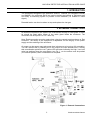
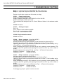
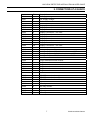
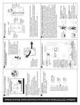
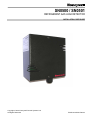
SN0500 / SN0501
REFRIGERANT GAS LEAK DETECTOR
INSTALLATION / USER GUIDE
Copyright © 2004 Honeywell Control Systems Ltd.
All Rights Reserved
EN1B-0014UK07 R0404
GAS LEAK DETECTOR INSTALLATION & USER GUIDE
CONTENTS
1. INTRODUCTION .................................................................................................... 3
2. EXTERNAL CONNECTIONS ................................................................................. 3
3. POWER SUPPLY................................................................................................... 4
4. ANALOGUE OUTPUTS ......................................................................................... 4
5. RELAY CONTACTS............................................................................................... 5
6. GAS DETECTION RANGE .................................................................................... 5
7. STANDARD DEFAULT SETTINGS ....................................................................... 6
8. CONNECTIONS AT A GLANCE............................................................................ 7
At the time of writing, this User Guide accurately describes the product. However, in
the course of development of our products we may make changes without
notification. Honeywell shall not be liable for errors or for incidental or consequential
damages, directly or indirectly, in connection with the furnishing, performance or
misuse of this product or document. All Installation and Commissioning work on
Honeywell equipment should be carried out by suitably qualified personnel only.
Normal safety precautions and good working practice should be observed, to prevent
damage or injury at all times. We welcome comments about our products and
documentation.
Contact us at :
Address on back cover of this guide
EN1B-0014UK07 R0404
2
GAS LEAK DETECTOR INSTALLATION & USER GUIDE
1. INTRODUCTION
The Honeywell Refrigerant Gas Detection sensors, SN0500 (for refrigerant R404a)
and SN0501 (for refrigerant R410) are used to detect the leakage of refrigerant gas
and notify a monitoring system or provide a local indication (i.e. audible or visual
signal).
Remedial action can then be taken to stop and replace the lost gas.
2. EXTERNAL CONNECTIONS
All external connections are made to the motherboard through a cable gland. A cable
tie should be fitted within 20mm of the cable gland inside the enclosure. The
connectors will accept wire of 0.5-1.5mm sq.
Note: Earth connection must be made when using the vented metal enclosure or Exd
enclosure. The safety of this equipment is dependent on the integrity of the power
supply and the earthing of the enclosure.
On power up the sensor may take some time (minutes up to hours) to fully normalize.
You can monitor this by checking the 0-10V output as it falls towards zero. If during
this normalisation period the red / yellow LED activates indicating the high / low level
relay has switched then the reset button (see Fig. 1.) on the sensor must be pushed
(if in latched position) after normalisation is complete.
Figure 1. External Connections
3
EN1B-0014UK07 R0404
GAS LEAK DETECTOR INSTALLATION & USER GUIDE
3. POWER SUPPLY
The Power supply is connected at Con 1 (see Fig. 1)
Green LED on - shows power connected.
Pin 1 = 0V,
Pin 2 = 12 to 24 VAC or 12 to 30VDC,
Pin 3 = Earth.
The 0V (pin 1) on the power supply terminal block (CON 1) can withstand 50V
AC or DC with respect to the 0V (Pin 1) on the output terminal block (CON 3). If
this is likely to be exceeded use an isolated power supply.
On the power supply side 12V is the minimum voltage at the terminals. Power
consumption is 4W max. It can draw 0.33Amp at 12V, so voltage drop along the
supply cable should be considered when selecting supply cable, type and length. For
example, for cable resistance 10ohm/100m allowing for the flow and return total cable
resistance for 100m is 20ohm and voltage drop along the cable is 6.6V. Minimum DC
supply then should be 19V.
If you need to use a cable of greater diameter that 1.5 mm sq, you can use a terminal
block at each sensor position capable of taking the larger cable and connect from that
into the CON1 terminal block using 1mm sq wire. Alternatively use local power
supplies to reduce cable runs and voltage loss.
4. ANALOGUE OUTPUTS
Analogue Outputs which indicate the concentration of gas refrigerant in the air, are at
Con 3 (see Figure 1.)
A two-core communication cable should be used to connect the outputs to a
monitoring and control system; a screen is not required.
Pin 1 = 0V
Pin 2 = 4-20mA. Load resistance must be less than 400Ω
Pin 3 = 0-10V.
Load resistance must be greater than 100Ω
Pin 4 = 0-5 V.
Load resistance must be greater than 10KΩ
When connecting the 4-20mA to the control panel, we suggest using Belden 8761,
22awg single pair shielded or alternatively an alarm type cable of 7/0.2mm, 22awg.
EN1B-0014UK07 R0404
4
GAS LEAK DETECTOR INSTALLATION & USER GUIDE
5. RELAY CONTACTS
Note: If changing any jumper - power must be removed.
There are two relays rated up to 1 Amp at 24V DC/AC. The status of the relays is
jumper selectable.
Relay 1 at Con 6. Low-level alarm. Yellow LED on when in alarm.
Normally closed when JP4 link inserted, JP3 link removed, as shown on Fig. 1.
Normally open when JP3 link inserted, JP4 link removed, as shown on Fig. 1.
Latching (manual reset by push button located next to CON 7) - Not latching
(automatic reset) set by JP8 see Fig. 1. for link position.
Alarm threshold level is set by pot RV1 and can be set by putting a meter between
TP0 (negative) and TP2 (positive) (below RV1) and adjusting RV1 (scale is 0 to 5V
e.g. 2.5V is 50% of scale).
Delayed response time is set at JP1 by inserting the link in the required position.
Default settings are:
Position 1: No delay
Position 2 : 1 Minute
Position 3 : 5 Minutes
Position 4 : 10 Minutes
Note: If changing any jumper - power must be removed.
Relay 2 at Con 7. High-level alarm. Red LED on when in alarm.
Normally open/closed when JP5 link inserted, as shown on Fig.1.
Latching (manual reset by push button located next to CON 7) / Not latching
(automatic reset) set by JP7 see Fig. 1. for link position.
Alarm threshold level is set by pot RV2 and can be set by putting a meter between
TP0 (negative) and TP3 (positive) (below RV2) and adjusting RV2 (scale is 0 to 5V
e.g. 2.5V is 50% of scale).
Delayed response time is set at JP2 by inserting the link in the required position.
Position 1 No delay
Position 2 1 Minute
Position 3 5 Minutes
Position 4 10 Minutes
Note: If changing any jumper - power must be removed.
6. GAS DETECTION RANGE
Gas Detection Range and default settings vary with model and set up, see below for
sample settings.
5
Gas
R404a
R410
Range
0-1000 PPM
0-1000 PPM
EN1B-0014UK07 R0404
GAS LEAK DETECTOR INSTALLATION & USER GUIDE
7. STANDARD DEFAULT SETTINGS
Relay 1
Relay 2
Low-level relay set at 500 PPM, NO, Auto reset mode
High-level relay set at 900 PPM, NO, Auto reset mode.
Delays on both alarm outputs are 0 minutes (no delay).
CON 1: Power Supply input
Power on indicated by Green LED.
Supply voltages to be either 12V to 24V AC or 12 to 30V DC
Power consumption is 4W max at 12V.
The connectors will accept wire of 0.5-1.5mm² Refer to Section 3 for maximum cable
run.
CON 2: Not Used.
CON 3: Analogue Output
Pin 1: 0V
Pin 2: 4-20mA. Load resistance<400Ω
Pin 3:0-10V. Load resistance>100Ω
Pin 4: 0-5V. Load resistance>10KΩ
CON 4: Plug-in detection sensor
CON 5: Not Used
CON 6: Relay 1 contacts (1Amp 24V AC/DC)
Low-level alarm. Indicated by Yellow LED.
Normally closed when JP4 link inserted, JP3 link removed, as shown on Fig. 1.
Normally open when JP3 link inserted, JP4 link removed, as shown on Fig. 1.
Latching (manual reset by push button located next to CON 7) / Not Latching set by
JP8 (see Fig. 1. in Connection Instructions)
Alarm Threshold level set by RV1 and can be set by putting a meter between TP0
(negative) and TP2 (positive) and adjusting RV1 (scale is 0 to 5V e.g. 2.5V is 50% of
scale).
Delayed response time set by JP1 link (see Fig. 1. in External Connections)
Position 1= No delay
Position 3=5 min
Position 2=1 min
Position 4=10 min
CON 7: Relay 2 contacts (1Amp 24V AC/DC)
High-level alarm. Indicated by Red LED on.
Normally open/closed when JP5 link inserted, as shown on Fig. 1.
Latching (manual reset by push button located next to CON 7) / Not Latching set by
JP7 (as above)
Alarm threshold level set by RV2 and can be set by putting a meter between TP0
(negative) and TP3 (positive) and adjusting RV2 (scale is 0 to 5V e.g. 2.5V is 50% of
scale).
Delayed response time is set by JP2 link (see Fig. 1. in External Connections).
Position 1= No delay
Position 3=5 min
Position 2=1 min
Position 4=10 min
If changing any jumper - power must be removed.
EN1B-0014UK07 R0404
6
GAS LEAK DETECTOR INSTALLATION & USER GUIDE
8. CONNECTIONS AT A GLANCE
Connector
CON1
CON1
CON1
Pin
1
2
3
Description
0V Supply Voltage.
24V Supply Voltage.
Earth.
CON2
CON2
CON2
CON2
CON2
CON2
CON2
CON2
CON2
CON2
1
2
3
4
5
6
7
8
9
10
Display Connection – not used.
Display Connection – not used.
Display Connection – not used.
Display Connection – not used.
Display Connection – not used.
Display Connection – not used.
Display Connection – not used.
Display Connection – not used.
Display Connection – not used.
Display Connection – not used.
CON3
CON3
CON3
CON3
1
2
3
4
Analogue Output – 0V.
Analogue Output – 4-20mA, load resistance <400Ω.
Analogue Output – 0-10V, load resistance >100Ω.
Analogue Output – 0-5V, load resistance>10KΩ.
CON4
CON4
CON4
CON4
CON4
CON4
1
2
3
4
5
6
Plug-in detection sensor module.
Plug-in detection sensor module.
Plug-in detection sensor module.
Plug-in detection sensor module.
Plug-in detection sensor module.
Plug-in detection sensor module.
CON5
CON5
CON5
1
2
3
RS485 Communication – A.
RS485 Communication – B.
RS485 Communication – Screen.
CON6
CON6
1
2
NO relay contact.
NO relay contact.
CON7
CON7
1
2
NO relay contact.
NO relay contact.
7
EN1B-0014UK07 R0404
Automation & Control Solutions
Refrigeration Control
Newhouse Industrial Estate
Motherwell
Lanarkshire ML1 5SB
Phone: (44) 01698 481698
Fax: (44) 01698 481699
www.honeywell.com/refrigeration
Subject to change without notice.
EN1B-0014UK07 R1204