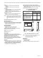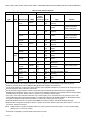
1
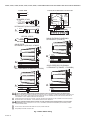
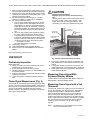
R7824, R7847, R7848, R7849, R7851,
R7852, R7861, R7886 Amplifiers
for 7800 SERIES and R7140 Relay Modules
PRODUCT DATA
indicate the presence of flame when used with 7800 SERIES
and R7140 Relay Modules. This is not European Community
(CE) approved for EC7810, EC7820, EC/RM7830 or EC/
RM7850 Relay Modules.
The R7848A,B Infrared Flame Amplifiers are solid state plugin amplifiers that respond to an infrared signal from a C7015
Infrared Flame Detector to indicate the presence of flame
when used with 7800 SERIES and R7140 Relay Modules.
The R7849A,B Ultraviolet Flame Amplifiers are solid state
plug-in amplifiers that respond to an ultraviolet signal from a
C7027, C7035 or C7044 Ultraviolet Flame Detector to indicate
the presence of flame when used with 7800 SERIES and
R7140 Relay Modules.
The R7851B Optical Flame Amplifiers are solid state plug-in
amplifiers that respond to optical signals from C7927 and C7962
Flame Detectors to indicate the presence of flame when used
with 7800 SERIES and R7140 Relay Modules.
The R7852A,B Infrared Flame Amplifiers are solid state plugin amplifiers that respond to an infrared signal from a C7915
Infrared Flame Detector to indicate the presence of flame
when used with 7800 SERIES and R7140 Relay Modules.
APPLICATION
The R7824C Rectification Flame Amplifier is a solid state
plug-in amplifier that responds to a rectified signal from a
C7024E,F Self-Check Ultraviolet Flame Detector to indicate
the presence of flame when used with the 24 Vdc RM7824
Relay Module.
The R7847A,B Rectification Flame Amplifiers are solid state
plug-in amplifiers that respond to a rectified signal from a
rectification type flame detector to indicate the presence of
flame when used with 7800 SERIES and R7140 Relay Modules.
The R7847C Self-Check Rectification Flame Amplifier is a
solid state plug-in amplifier that responds to a rectified signal
from a C7012E,F Self-Check Ultraviolet Flame Detector to
The R7851C Dynamic Self-Check Optical Flame Amplifier is a
solid state plug-in amplifier that responds to ultraviolet signals
from C7961E Dynamic Shutter-Check ultraviolet flame
detectors to indicate the presence of flame when used with
7800 SERIES and R7140 Relay Modules.
The R7861A Self-Check Ultraviolet Flame Amplifier is a solid
state plug-in amplifier that responds to an ultraviolet signal
from a C7061 Self-Check Ultraviolet Flame Detector to
indicate the presence of flame when used with 7800 SERIES
and R7140 Relay Modules.
Contents
Application ........................................................................
Features ...........................................................................
Specifications ...................................................................
Ordering Information ........................................................
Installation ........................................................................
Checkout ..........................................................................
Amplifiers R7847B,C, R7861A,
R7886, R7851C or R7852B
SIL3
Capable
1
2
2
2
5
7
65-0109-14
R7824, R7847, R7848, R7849, R7851, R7852, R7861, R7886 AMPLIFIERS FOR 7800 SERIES AND R7140 RELAY MODULES
The R7886A Dynamic Self-Check Ultraviolet Amplifier is a
solid state plug-in amplifier that responds to a pulsed direct
current signal from a C7076A,C Ultraviolet Flame Detector
with adjustable sensitivity to indicate the presence of flame
when used with 7800 SERIES and R7140 Relay Modules.
• R7824C, R7847C Dynamic Self-Check Rectification
Amplifier, R7851C Dynamic Self-Check Optical Flame
Amplifier, R7861 Self-Check Ultraviolet Flame
Amplifier and R7886A Dynamic Self-Check Ultraviolet
Amplifier test the detectors and all electronic
components in the flame detection system 12 times
per minute. The 7800 SERIES and R7140 Relay Module
locks out on safety shutdown with flame detection
system failure.
FEATURES
• Flame failure response time of 0.8 or 1 second; or 2.0
or 3.0 seconds, depending on the amplifier and relay
module selected. See Table 1.
NOTE: R7824C, Series 2 or greater and R7847C Series 4
or greater, pulse the shutter when signal of 1.5 Vac
is sensed. Display readings of 0.7 to 2.4 Vdc are
common.
• Plug-in to 7800 SERIES and R7140 Relay Module
through printed circuit board edge connector keyed
for proper orientation.
SPECIFICATIONS
• Flame signal test jacks measure amplifier flame signal
voltage.
Models:
Flame Detection Systems (see Table 2):
Rectification:
R7824C for use with C7024E,F Solid State Ultraviolet
Detectors.
R7847A,B for use with flame rods or C7012A,C Solid State
Ultraviolet Detectors.
R7847C for use with C7012E, F Solid State Ultraviolet
Detectors.
• 0.0 to 5.0 Vdc Flame signal strength reading range.
• Color coded label identifies flame detection type:
— Green—rectification. Red—infrared.
— Purple—ultraviolet.
Blue—pulsed rectification.
— White—optical.
• R7847B, R7848B, R7849B Dynamic Ampli-Check®
circuitry tests all flame amplifier components 12 times
per minute. The 7800 SERIES and R7140 Relay Module
locks out on safety shutdown with amplifier failure.
ORDERING INFORMATION
When purchasing replacement and modernization products from your TRADELINE® wholesaler or distributor, refer to the
TRADELINE® Catalog or price sheets for complete ordering number.
If you have additional questions, need further information, or would like to comment on our products or services, please write or
phone:
1. Your local Honeywell Automation and Control Products Sales Office (check white pages of your phone directory).
2. Honeywell Customer Care
1985 Douglas Drive North
Minneapolis, Minnesota 55422-4386
3. http://customer.honeywell.com or http://customer.honeywell.ca
International Sales and Service Offices in all principal cities of the world. Manufacturing in Australia, Canada, Finland, France,
Germany, Japan, Mexico, Netherlands, Spain, Taiwan, United Kingdom, U.S.A.
65-0109—14
2
R7824, R7847, R7848, R7849, R7851, R7852, R7861, R7886 AMPLIFIERS FOR 7800 SERIES AND R7140 RELAY MODULES
Infrared:
R7848A,B for use with C7015 Infrared (lead sulfide)
Detector.
R7852A,B for use with C7915 Infrared (lead sulfide)
Detector.
Ultraviolet:
R7849A,B for use with C7027/C7035/C7044 Minipeeper
Ultraviolet Detectors.
R7861A for use with C7061A Ultraviolet Detector.
R7886A for use with C7076A,D Ultraviolet Detectors with
adjustable sensitivity.
Optical:
R7851B for use with C7927 and C7962 Flame Detectors.
R7851C for use with C7961E Flame Detectors.
Canadian Standards Association Certified: LR95329-3.
Factory Mutual Approved: Report 1V9A0.AF. (R7851B, Report
Number 3011020, June 16, 2003), R7851C (Report number
3020842, April 12, 2005.)
SwissRe (formerly Industrial Risk Insurers) Acceptable.
EC7810, EC7820, EC/RM7830, 1.0
EC/RM7850
2.0
NOTE: R7824C, Series 2 or greater and R7847C Series 4 or
greater, pulse the shutter when signal of 1.5 Vac is
sensed. Display readings of 0.7 to 2.4 Vdc are common.
EC/RM7823, EC/RM7885, EC/
RM7890, RM7895, RM7896,
RM7897, RM7898, RM7888,
RM7838, RM7800, RM7840,
R7140
0.8
3.0
RM7824
N/A
3.0
Table 1. Relay Module Flame Failure
Response Time (FFRT).
Flame Failure Response
Time (FFRT) in seconds
0.8 or 1
Relay Module
Flame Failure Response Time: See Table 1.
Flame Signal (Volts dc):
Minimum Acceptable: 1.25 Vdc.
Flame Signal Voltage Range (displayed on Keyboard Display
Module or measured with a 1M ohm/volt meter plugged into
amplifier test jacks): 0.0 to 5.0 Vdc.
–
S
2.0 or 3.0
+
FLAME AMPLIFIER
Environmental Ratings:
Ambient Temperature:
Operating: -40°F to 140°F (-40°C to 60°C).
Storage: -40°F to 150°F (-40°C to 65°C).
Humidity: Operating 85% rh continuous, noncondensing.
Vibration: Continuous 0.5G environment.
3
(76)
3/8 (9)
Weight: 2.5 oz (71g), unpacked.
3-9/16 (91)
Dimensions: See Fig. 1.
7/8
(23)
M11460
SIL 3 Capable:
The Amplifiers R7847B,C, R7861A, R7886, R7851C or
R7852B used with the appropriate flame detector and used in
Relay Module EC7810A, 20A, 30A, 40L, 50A;
RM7800[E,G,L,M], 30A, 38[A,B,C], 40[E,G,L,M] 50A,
90[A,B,C,D], 97[A,C], 98A is SIL 3 Capable in a properly
designed Safety Instrumented System. See form number 650312 for Certificate Agreement.
Fig. 1. Flame amplifier dimensions in in. (mm).
NOTE: EN298 Approved: When these amplifiers are used
with an EC7810, EC7820, EC/RM7830, or
EC/RM7850 Relay Module.
Accessories:
Flame Simulators:
Rectification: 123514A.
Ultraviolet: 203659.
Flame Detectors (ordered separately): select from Table 2.
Approvals:
Underwriters Laboratories Inc. Listed: File no. MP268, Guide
no. MCCZZ: R7847A, R7847B, R7847C, R7861A, R7886A,
R7848A, R7848B, R7849A, R7849B, R7851B, R7851C.
Underwriters Laboratories Inc. Component Recognized: File
no. MP268, Guide no. MCCZZ: R7824C.
3
65-0109—14
R7824, R7847, R7848, R7849, R7851, R7852, R7861, R7886 AMPLIFIERS FOR 7800 SERIES AND R7140 RELAY MODULES
Table 2. Flame Detection Systems.
Plug-in Flame Signal Amplifiers
Type
Color
Rectification Green
Infrared
Fuel
Type
Models
R7824Cb,c,h 3
No
R7847Ag
0.8/1 or 2/3 Gas
No
R7847Ag
2/3
Gas, oil, Ultraviolet (Purple
coal
Peeper®)
Dynamic Ampli- R7847Bd,g
Check®
0.8/1 or
2/3
Gas
Dynamic Ampli- R7847Bd,g
Check®
2/3
Gas, oil, Ultraviolet (Purple
coal
Peeper®)
C7012A,C
Dynamic Self
Check
R7847Cc,h
3
Gas, oil, Ultraviolet (Purple
coal
Peeper®)
C7012E,F
No
R7848A
2/3
Gas, oil, Infrared (Lead
coal
Sulfide)
C7015
Dynamic Ampli- R7848Bd
Check®
2/3
Gas, oil, Infrared (Lead
coal
Sulfide)
C7015
No
2/3
Gas, oil, Infrared (Lead
coal
Sulfide)
C7915
Dynamic Ampli- R7852Bb
Check®
2/3
Gas, oil, Infrared (Lead
coal
Sulfide)
C7915
No
0.8/1 or
2/3
Gas, oil
Ultraviolet
(Minipeeper)
C7027, C7035, C7044f
Dynamic Ampli- R7849Bd
Check®
0.8/1 or
2/3
Gas, oil
Ultraviolet
(Minipeeper)
C7027, C7035, C7044f
Dynamic SelfCheck
R7861Ac,e
0.8/1 or
2/3
Gas, oil, Ultraviolet
coal
Blue
Dynamic SelfCheck
R7886Ac,e
2/3
Gas, oil, Ultraviolet (Adjustable C7076
coal
Sensitivity)
White
Dymanic Ampli- R7851B
Check®
0.8/1 or 2/3 Gas, oil, Optical (UV, Visible
coal
Light)
C7927, C7962
Dynamic SelfCheck
2/3
C7961
Red/
White
Optical
Model
Dymanic SelfCheck
Red
Ultraviolet
Self-Checking
Applicable Flame Detectors
Flame
Failure
Response
Time (sec)a
Purple
R7852A
R7849A
R7851Cc
Gas, oil, Ultraviolet (Purple
coal
Peeper®)
C7024E,F
Rectifying Flame Rod C7004, C7007, C7011
Complete Assemblies:
Holdersi
C7008, C7009, Q179
C7012A,C.
Rectifying Flame Rod C7004, C7007, C7011
Complete Assemblies:
Holdersi
C7008, C7009, Q179
Gas, oil, Optical (UV only)
coal
C7061
a Flame
Failure Response Time (FFRT) depends on selection of amplifier and 7800 SERIES and R7140 Relay Module.
is used only with the 24 Vdc RM7824 Relay Module and C7024E,F Flame Detectors.
c Circuitry tests all electronic components in flame detection system (amplifier and detector) 12 times a minute during burner operation and shuts down burner if detection system fails.
d
Circuitry tests flame signal amplifier 12 times a minute during burner operation and shuts down burner if amplifier fails.
e 200/220/240 Vac applications require a 120 Vac, 10 VA minimum stepdown transformer (not provided) to drive the shutter. Applies
to R7886A series 2 or greater; R7861 series 1 or greater. Fig. 2 shows flame detector wiring.
f
Use C7027, C7035 and C7044 Flame Detectors only on burners that cycle on-off at least once every twenty-four hours. Use
C7061A Ultraviolet Detector with R7861A Amplifier or C7076A Flame Detector with R7886A Amplifier as ultraviolet flame detection system for appliances with burners that remain on continuously for twenty-four hours or longer.
g R7847A,B Amplifiers with 0.8/1 second FFRT should NOT be used with C7012A,C Solid State Ultraviolet Detectors.
h R7824C Series 2 and greater and R7847C Series 4 or greater, check flame detector system when flame reaches 1.5 Vdc or at
4.5 seconds, whichever occurs first.
b R7824C
NOTE:
i
R7824C Series 2 or greater and R7847C Series 4 or greater, pulse the shutter when signal of 1.5 Vdc is sensed. Display
readings of 0.7 to 2.4 Vdc are common.
Order flame rod separately; see flame detector Instructions for holder.
65-0109—14
4
R7824, R7847, R7848, R7849, R7851, R7852, R7861, R7886 AMPLIFIERS FOR 7800 SERIES AND R7140 RELAY MODULES
1.
CAUTION
Equipment Damage Hazard.
Incorrect combination of relay module, amplifier
and flame detector can cause equipment damage.
In infrared applications (C7015 Infrared Flame Detector
and R7848 Amplifier) using the RM7890 Relay Module
with software version 4004 or less requires a tensecond delay to start sequence. This applies only to the
initial power of the RM7890.
2.
3.
4.
Installing Flame Detector
INSTALLATION
NOTE: Table 2 lists flame detection systems available for use
with 7800 SERIES and R7140 Relay Modules. Be
sure to use the correct combination of amplifier and
flame detector.
When Installing this Product...
1.
2.
3.
4.
Align the amplifier circuit board edge connector with the
keyed receptacle on the 7800 SERIES and R7140 Relay
Module. Be sure the amplifier nameplate faces away
from the Relay Module.
Push in the amplifier until the circuit board is fully
inserted into the receptacle and then push the amplifier
toward the 7800 SERIES and R7140 Relay Module
retaining clasp.
Be sure the amplifier is firmly in place.
Perform all required checkout tests.
Read these instructions carefully. Failure to follow them
could damage the product or cause a hazardous condition.
Check the ratings given in the instructions and on the
product to make sure the product is suitable for your
application.
Installer must be a trained, experienced, flame safeguard
control technician.
After installation is complete, check out the product operation as provided in these instructions.
Proper flame detector installation is the basis of a safe and
reliable flame safeguard installation. Refer to the Instructions
packed with the flame detector and the equipment
manufacturer instructions.
Keep the flame signal leadwires as short as possible from the
flame detector to the wiring subbase. Capacitance increases
with leadwire length, reducing the signal strength. The
maximum permissible leadwire length depends on the type of
flame detector, leadwire and conduit. However, the ultimate
limiting factor for the flame detector leadwire is the flame
signal; see Table 3 in the Checkout section.
WARNING
Electric Shock Hazard.
Can cause electrical shock, serious injury or death.
Disconnect the power supply before beginning
installation. More than one power supply disconnection
can be involved.
IMPORTANT
1. Wiring must comply with all applicable codes, ordinances and regulations
2. Wiring (where required) must comply with NEC Class
1 (Line Voltage) wiring.
3. Perform all required checkout tests after installation is
complete.
CAUTION
Equipment Damage Hazard.
Can cause equipment damage.
Disconnect 7800 SERIES and R7140 Relay Module
power before removing amplifier.
Fig. 2. Installing flame signal amplifier.
Installing Plug-In Flame
Signal Amplifier (Fig. 2)
Wiring
WARNING
WARNING
Electrical Shock Hazard.
Can cause severe injury, death or property damage.
Disconnect power supply before beginning installation.
More than one disconnection can be involved.
Electric Shock Hazard.
Can cause severe injury, death or property damage.
Disconnect the power supply before beginning
installation. More than one power supply disconnection
can be involved.
5.
6.
5
Remove the 7800 SERIES and R7140 Relay Module
from the wiring subbase.
Refer to Fig. 3 for proper flame detector wiring.
65-0109—14
R7824, R7847, R7848, R7849, R7851, R7852, R7861, R7886 AMPLIFIERS FOR 7800 SERIES AND R7140 RELAY MODULES
C7076A,D ULTRAVIOLET DETECTOR
FLAME ROD
XF
XG
6
INFRARED (C7915)
F
G
BLUE
WHITE
F
4
SHUTTER
8
2a
L1 1
3
SHUTTER
L2 2
F
5
BLUE
YELLOW
BLACK
BLACK
GREEN
SELF-CHECKING ULTRAVIOLET (C7061A)
2
F
G
22
N
BLUE
G
3
F
G
22
BLUE
YELLOW
WHITE
L2
L1
L2
WHITE
BLACK
BLACK
F
G
22
L2
5
22
L2
3
L2
WHITE
3
BLUE
YELLOW
WHITE
WHITE
RED
BLACK
1
! CAUTION: EQUIPMENT DAMAGE HAZARD. INCORRECT WIRING POLARITY CAN DAMAGE OR DESTROY UV SENSING TUBES.
CONNECT FLAME DETECTOR WIRES ACCORDING TO FOOTNOTES 1 AND 2 TO PREVENT UV SENSING TUBE DAMAGE.FLAME DETECTOR
LEADS ARE COLOR CODED. THE BLUE LEAD MUST BE CONNECTED TO THE F TERMINAL AND THE WHITE MUST BE CONNECTED TO
THE G TERMINAL. THE UV SENSING TUBE IS POLARITY SENSITIVE.
2
FLAME DETECTOR LEADS ARE COLOR CODED. THE BLUE LEAD MUST BE CONNECTED TO THE F TERMINAL AND THE YELLOW MUST
BE CONNECTED TO THE G TERMINAL. THE UV SENSING TUBE IS POLARITY SENSITIVE.
3
! CAUTION: EQUIPMENT DAMAGE HAZARD. INCORRECT VOLTAGE CAN DAMAGE SHUTTER MECHANISM ONLY ON EC7800 SERIES
RELAY MODULES. INSTALL A 200/220/240 VAC TO 120 VAC, 10VA MINIMUM, STEPDOWN TRANSFORMER (NOT PROVIDED) TO DRIVE
THE SHUTTER MECHANISM.
4
DO NOT USE 0.8/1 SECOND FFRT AMPLIFIER WITH C7012A,C FLAME DETECTOR.
5
GND (GREEN) LEAD WIRE ON C7961E ONLY.
M27852
Fig. 3. Flame detector wiring.
65-0109—14
L1 (HOT)
L2 (COMMON)
SOLID STATE SELF-CHECKING
ULTRAVIOLET (C7024E,F – E SHOWN)
2
YELLOW
WHITE
C7076A
OR
C7076D
TERMINAL
BLOCK
4
2
F
G
L1
L2
GND
EARTH
GROUND
SOLID STATE SELF-CHECKING
ULTRAVIOLET (C7012E,F)
WHITE
SOLID STATE
ULTRAVIOLET (C7012A,C, C7961E)
2
2b
7800 SERIES
OPTICAL C7927A
G
7
G
BLUE
BLUE
1
3b
3
G WHITE
F
3a
5
ULTRAVIOLET (C7027/C7035/C7044)
1
REMOTE
SENSOR
F
6
R7824, R7847, R7848, R7849, R7851, R7852, R7861, R7886 AMPLIFIERS FOR 7800 SERIES AND R7140 RELAY MODULES
7.
8.
9.
10.
11.
12.
13.
Disconnect power supply before making wiring connections to prevent electrical shock and equipment damage.
All wiring must comply with appropriate electrical codes,
ordinances and regulations including NEC Class 1 (Line
Voltage) wiring where required.
Use recommended wire size and type no. 18 copper
conductors TTW(60C) or THW (75C) or THNN(90C).
Use recommended wire routing:
a. Keep the flame signal leadwire as short as possible
from the detector to the 7800 SERIES and R7140
Relay Module. The maximum permissible leadwire
length depends on the type of leadwire, conduit type
and leadwire diameter. The ultimate limiting factor for
flame signal leadwire length is the flame signal voltage.
b. Do not run high voltage ignition transformer wires in
the same conduit with the flame detection wiring.
c. If the flame detector leadwires are not long enough
to reach the 7800 SERIES and R7140 Relay Module
electrical connectors, make splices in a junction box.
(1) Enclose scanner wiring without armor cable in
metal cable or conduit.
(2) Follow flame detector Instructions.
Check wiring, see Fig. 3.
Install 7800 SERIES and R7140 Relay Module.
Restore power to the 7800 SERIES and R7140 Relay
Module.
CAUTION
Equipment Damage Hazard.
Improper wiring can destroy ultraviolet sensing
tube.
Carefully follow polarity sensitive wiring instructions for
the C7027, C7035, C7044, C7012, C7024, C7061,
C7961 and C7076. Reversing the leadwires, even
momentarily, can destroy the ultraviolet sensing tube.
NEGATIVE (-)
METER LEAD
POSITIVE (+)
METER LEAD
ONE
MEGOHM/VOLT
METER
FLAME SIMULATOR
TEST JACK
Flame detector wiring is shown in Fig. 3.
M11459A
CHECKOUT
Fig. 4. Flame signal measurement with meter.
1.
Preliminary Inspection
Make certain that:
1. Wiring connections are correct and all terminal screws
and electrical connections are tight.
2. Proper flame failure response time is selected.
3. Amplifier is securely mounted on the 7800 SERIES and
R7140 Relay Module.
4. Detectors are properly positioned and cleaned according
to Detector Instructions.
5. Correct combination of amplifier and flame detector is
used.
2.
3.
Connect blue leadwire from detector to terminal F and
white leadwire from C7027/C7035/C7044/C7061 to terminal G.
Connect blue leadwire from detector to terminal F and
yellow leadwire from C7012/C7024/C7961 to terminal G.
Follow lightoff Instructions for applicable 7800 SERIES
and R7140 Relay Module.
Measuring Flame Signal With
Keyboard Display Module
Consult Instructions for applicable 7800 SERIES and R7140
Relay Module or Keyboard Display Module.
Flame Signal Measurement (Fig. 4)
Measuring Flame Signal with a Volt
Ohmmeter
Flame signal can be measured at the Flame Signal Test Jacks,
see Fig. 4, and at the Keyboard Display Module. Measure the
flame signal at the appropriate times defined in the Checkout
section; see applicable 7800 SERIES and R7140 Relay
Module Instructions. See Table 3 for acceptable and maximum
flame signal voltage strengths.
Two test jacks, positive and negative (Com) are accessible on
the top of the amplifier when plugged into the 7800 SERIES
and R7140 Relay Module. These jacks are provided for
monitoring flame signal strength. Use a one megohm/volt
meter to measure the flame signal strength. Connect the
positive meter lead (red) to the positive (+) amplifier test jack
and the negative meter lead (black) to the negative (-) amplifier
test jack. The test jacks use standard 0.180 inch diameter
voltmeter probes. A minimum 1.25 Vdc flame signal is
required.
NOTE: The probes need to tip toward the relay module in
order to make electrical contact.
7
65-0109—14
R7824, R7847, R7848, R7849, R7851, R7852, R7861, R7886 AMPLIFIERS FOR 7800 SERIES AND R7140 RELAY MODULES
Table 3. Flame signal.
Flame Detector
Flame Rod
C7012A,Cc
C7015A
R7848A,Bb
C7024E,F
R7824Cd,e
C7027A
C7035A
C7044A
C7927
C7962
C7915
R7849A,Bb
C7061A
R7861Ad
C7076A,D
R7886Ad
C7961E
R7851Cd
Minimum Acceptable
Steady dc Voltagea
1.25 Vdc
Flame Signal Amplifier
R7847A,Bb
Maximum Expected dc Voltage
5.0 Vdc at Keyboard Display Module
or on volt-ohmmeter.
R7851Bb
R7852A,Bb
a This
minimum or stronger signal can be easily obtained if the detector is correctly installed and positioned to properly sense the
flame. Obtain this voltage before completing checkout.
b The flame amplifiers are Ampli-Check® type.
c Adjust slightly, or face the pipe down, or extend the sight pipe on C7012A,C applications to obtain a maximum flame signal
reading less than 5.0 volts.
d The flame signal amplifier circuitry is tested one-half second every five seconds during burner operation and shuts down the
burner if the amplifier fails (all installations).
e R7824C Series 2 or greater and R7847C Series 4 or greater, pulse the shutter when the flame signal reaches 1.5 Vdc.
NOTE: R7824C, Series 2 or greater, pulse shutter when signal of 1.5 Vdc is sensed. Display readings of 0.7 to
2.4 Vdc are common.
The flame signal for the pilot alone, the main burner flame
alone, and both together must be steady and a minimum of
1.25V. If the flame signal is unsteady, or less than the
minimum acceptable voltage, check the flame detector
installation and circuitry in the following procedure.
1.
2.
3.
Check the supply voltages at terminals (L1) and L2 (N).
Make sure the master switch is closed, connections are
correct, and the power supply is of the correct voltage
and frequency and is sinusoidal.
Check the detector wiring for defects including:
a. Incorrect connections.
b. Wrong type of wire.
c. Deteriorated wire.
d. Open circuits.
e. Short circuits.
f. Leakage paths caused by moisture, soot or accumulated dirt.
For a flame rod, make sure:
a. There is enough ground area.
b. The flame rod is properly located in the flame.
4.
5.
6.
7.
8.
9.
10.
c. Temperature at the flame rod insulator is no greater
than 500°F (260°C).
For all optical detectors, clean the detector viewing
window, lens, and inside of the sight pipe as applicable.
With the burner running, check the temperature at the
detector. If it exceeds the detector maximum rated
temperature:
a. Add a heat block to stop conducted heat traveling
up the sight pipe.
b. Add a shield or screen to reflect radiated heat.
c. Add cooling (refer to sight pipe ventilation in the
detector Instructions).
Make sure that the flame adjustment is not too lean.
Make sure the optical detector is properly sighting the
flame.
If necessary, resight or reposition the detector.
If you cannot obtain proper operation, replace the
plug-in amplifier.
If you cannot yet obtain proper operation, replace the
flame detector.
IMPORTANT
If you make any changes to the flame detection
system, repeat all required Checkout tests in
Checkout section of the Instructions for the
applicable 7800 SERIES and R7140 Relay Module.
Automation and Control Solutions
Honeywell International Inc.
1985 Douglas Drive North
Golden Valley, MN 55422
customer.honeywell.com
® U.S. Registered Trademark
© 2011 Honeywell International Inc.
65-0109—14 M.S. Rev. 06-11
Printed in U.S.A.