1
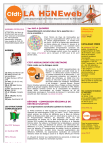
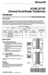
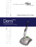
43191680-105
Auxiliary Switch
INSTALLATION INSTRUCTIONS
APPLICATION
INSTALLATION
The 43191680-105 Dual Auxiliary Switch provides two
independent, spdt switching functions. Switching points
are adjustable over the full length of the actuator stroke; for
example, the switch can be used to switch pumps at any
point or to provide remote indication of any specific stroke
position. These switches are used with valve actuators as
shown in Table 1. The switches are furnished factory wired
to the terminal block. Fig. 1 illustrates the parts furnished
with this switch and the wiring connections.
When Installing this Product...
IMPORTANT
These switches are rated at 24 Vac maximum.
1 Read these instructions carefully. Failure to follow
them could result in the equipment not operating
properly.
2 Check the part numbers in the preceding section to
be sure that the product is suitable for your application.
3 The installer must be a trained, experienced service
technician.
4 After completing installation, use these instructions
to check product operation.
CAUTION
Table 1. Applicable Actuators for
43191680-105 Dual Auxiliary Switches.
Disconnect the power supply to the auxiliary
potentiometer and actuator before beginning
installation to prevent electrical shock or equipment damage.
Spring Action on
Power Failure
Actuator
ML6425A
Extends stem
ML6425B
Retracts stem
ML7425A
Extends stem
1 Remove actuator cover.
ML7425B
Retracts stem
2 Mount the auxiliary switch assembly and terminal
label on the actuator base. Make sure the two tabs
on the bottom of the switch assembly slip snugly into
the slots provided. See Fig. 2.
Mounting, Connecting, and Adjusting
SI
S2
3
S1
1
2
3
1
S1
S2
2
S2
6 4
5 9
7 8
6 4
5 9
7 8
1
2
3
4
5
6
C8394
C8393
Fig. 1. Auxiliary switch parts and wiring.
Fig. 2. Installing auxiliary switch assembly.
3 Secure auxiliary switch assembly by pressing top
back until assembly snaps into place. See Fig. 3.
Copyright © 1997 Honeywell Inc. • All Rights Reserved
X-XX UL
63-2524
43191680-105 AUXILIARY SWITCH
S1
S2
C8395
Fig. 3. Securing auxiliary switch assembly.
M6629
4 Secure terminal block and terminal label with Phillips
head screws. See Fig. 4 .
Fig. 5. Removing spring retaining clip
and releasing manual spring handle.
6 Adjust switching point for each switch. See Fig. 6.
a.
4 MM
Using manual spring handle on the actuator,
adjust the actuator shaft to the required
switching point for Switch S1.
NOTE: Turning the spring handle clockwise
extends the actuator shaft. When the
shaft gets to the required position,
press the handle down to hold the
shaft in position. Turning the spring
handle requires two hands, one to
turn the handle and the other to hold
it in place on each consecutive turn.
Observe the preceding caution and
release the handle only as noted in
the preceding Step 5.
S1
S2
3 MM
C8396
Fig. 4. Securing terminal block and label.
b.
CAUTION
Loosen the Phillips head set screw on the
cam for Switch S1, set the cam to the required
position, and tighten the set screw.
c.
Repeat the preceding Steps 6a and 6b for
Switch S2.
The manual spring handle is under tension and
could turn quickly when lifted resulting in injury to
fingers pinched between the handle and plastic
casing. Maintain handle orientation while lifting and
remove fingers quickly when releasing.
5 Remove manual spring handle retaining clip, if
necessary, and lift and release the handle. See
Fig. 5. The easiest way to perform this operation
safely is to:
a. Remove the retaining clip (shipping stop) and
discard.
b. Wedge a small, flat-bladed screwdriver under
the manual spring handle at the point marked
in Fig. 5 and pry up the handle.
63-2524
2
43191680-105 AUXILIARY SWITCH
Wiring
Route field wiring in through the conduit opening in the
bottom of the actuator, connect to the switch assembly
terminal block according to the job drawings, and replace
the actuator cover. See Fig. 1 for terminal identification.
S1
S2
CAUTION
1 X MAX.
Disconnect the power supply to the auxiliary
switches and actuator before wiring to prevent
electrical shock or equipment damage.
All wiring must comply with local codes, regulations, and
ordinances.
100
i i i i
i i
i
CHECKOUT
i i i
i
i i iiii
i
ii
iiiii
0
ii
iiii iii
iii
i i i iii
i
i i i
i i i
i
i i
Drive actuator shaft fully up and fully down and check the
function of the auxiliary switches in the control system.
iiiiiiiii
C8397
Fig. 6. Adjusting switching points.
3
63-2524
43191680-105 AUXILIARY SWITCH
Home and Building Control
Honeywell Inc.
Honeywell Plaza
P.O. Box 524
Minneapolis, MN 55408-0524
63-2524 G.C. 1-97 Printed in U.S.A
Home and Building Control
Honeywell Limited-Honeywell Limitée
155 Gordon Baker Road
North York, Ontario
M2H 2C9
4
Helping You Control Your World®