1
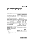
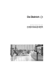
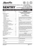
VR8300A Continuous Pilot Combination
Gas Control
INSTALLATION INSTRUCTIONS
APPLICATION
Body Pattern:
Straight-through body pattern.
These continuous pilot gas controls are used in gas-fired
appliances with capacities up to 200 cfh at 1 in. wc
pressure drop (5.7 cmh at 0.25 kPa) on natural gas.
Included are a manual valve, safety shutoff, two automatic
operators, and a pressure regulator. See Table 2 for
temperature range and regulator type.
Inlet x Outlet Sizes Available:
1/2 x 1/2 in., 1/2 x 3/4 in., and 3/4 x 3/4 in. (factory-installed
inlet flange).
The VR8300 setup for natural gas includes a 39369 LP
Conversion Kit. The kit contains a new cap screw, a
pressure regulator adjustment screw, a tapered spring and
a conversion label. The control must be equipped with a
standard servo pressure regulator. Step-opening gas
controls cannot be converted.
Adapters:
Adapters available for 1/2 and 3/4 in. straight and angle
connections. Refer to Table 3.
Electrical Ratings:
Voltage and Frequency: 24 Vac, 50/60 Hz.
Current Draw: 0.70A.
Capacity:
Size (Inlet x Outlet)
Capacity at 1 in. wc
Pressure Drop a
Minimum Regulated
Capacity
Maximum Regulated
Capacity
1/2 in. x 1/2 in.
180 cfh (5.1 cmh)
30 cfh (0.8 cmh)
225 cfh (6.4 cmh)
1/2 in. x 3/4 in.
190 cfh (5.4 cmh)
30 cfh 0.8 cmh)
290 cfh (8.2 cmh)
3/4 in. x 3/4 in.
200 cfh (5.7 cmh)
30 cfh (0.8 cmh)
300 cfh (8.5 cmh)
aCapacity based on 1000 Btu/cu ft, 0.64 specific gravity natural gas at 1 in. wc pressure drop (37.3 MJ/cu m, 0.64 specific
gravity natural gas at 0.25 kPa pressure drop).
Table 3. Flange Part Numbers.
Use conversion factors in Table 1 to convert capacities for
other gases.
Table 1. Gas Capacity Conversion Factors.
Gas
Specific
Gravity
Multiply Listed
Capacity By
Manufactured
0.60
0.516
Mixed
0.70
0.765
Propane
1.53
1.62
Table 2. Temperature Range and Regulator Type.
Model
Number
VR8300A
Ambient
Temperature Range
°F
°C
Regulator
Type
0° to 175° 18° to 79° Standard-opening
®U.S. Registered Trademark
Copyright © 1998 Honeywell Inc. • All Rights Reserved
Part Number
Inlet/Outlet
Pipe Size
1/2 in. NPT
3/4 in. NPT
Flange
Type
Without Hex
Wrench
With Hex
Wrench
Straight
393690-6
393690-16
Elbow
393690-3
393690-13
Straight
393690-4
393690-14
Elbow
393690-5
393690-15
NOTE: Flange kits include one flange with attached
O-ring and fan mounting screw.
Approvals:
International Approval Services Listed: L2025007.
Australian Gas Association Certificate: Applied for.
Delta C: Pending approval.
X-XX UL
69-0668-1
VR8300A CONTINUOUS PILOT COMBINATION GAS CONTROL
Converting Between Natural and LP Gas
INSTALLATION
WARNING
When Installing this Product…
Fire or Explosion Hazard.
Can cause property damage, severe injury,
or death.
1. Do not use a gas control set for natural gas on
LP gas or a gas control set for LP gas on
natural gas.
2. When making the conversion, the main and
pilot burner orifices MUST be changed to
meet the specifications of the appliance
manufacturer.
1. Read these instructions carefully. Failure to follow
them could damage the product or cause a hazardous condition.
2. Check the ratings given in the instructions and on
the product to make sure the product is suitable for
your application.
3. Installer must be a trained, experienced service
technician.
4. After installation is complete, check out product
operation as provided in these instructions.
Standard or slow-opening gas controls can be converted
from one gas to another. To convert from natural gas to
LP, use the 393691 LP Conversion Kit that is included with
the VR8300A Gas Control. To convert from LP to natural
gas, use the 394588 Natural Gas Conversion Kit (order
separately). Step-opening gas controls cannot be converted.
WARNING
Fire or Explosion Hazard.
Can cause property damage, severe injury,
or death.
Follow these warnings exactly:
1. Disconnect power supply before installing or
servicing.
2. To avoid dangerous accumulation of fuel gas,
turn off gas supply at the appliance service
valve before starting installation, and perform
Gas Leak Test after completion of installation.
3. Do not bend pilot tubing at gas control or pilot
burner after compression fitting has been
tightened, or gas leakage at the connection
may result.
4. Always install sediment trap in gas supply line
to prevent contamination of gas control.
5. Do not force gas control knob. Force or
attempted repair may result in fire or explosion. Use only your hand to push down the
reset button or turn the gas control knob.
Never use any tools. If the gas control knob or
reset button does not operate by hand, the
gas control should be replaced by a qualified
service technician.
To convert the control from one gas to another:
1. Turn off the main gas supply to the appliance.
2. Remove the regulator cap screw and pressure
regulator adjusting screw. See Fig. 5.
3. Remove the existing spring.
4. Insert the replacement spring with the tapered end
down. See Fig. 1.
5. Install the new plastic pressure regulator adjustment
screw so that the top of the screw is flush (level) with
the top of the regulator. Turn the pressure regulator
adjustment screw clockwise
six complete
turns. This provides a preliminary pressure setting of
about 10.0 in. wc (2.5 kPA) for an LP regulator and a
3.5 in. wc (0.9 kPA) for a natural gas regulator.
6. Check the regulator setting with a manometer or by
clocking the gas meter. See the Startup and
Checkout section.
7. Install the new cap screw.
8. Mount the conversion label on the control.
9. Install the control and the appliance according to the
appliance manufacturer instructions.
CAUTION
Equipment Hazard.
Improper installation can burn out thermostat
heat anticipator.
Do not apply a jumper across or short the valve
coil terminals.
Install Adapters to Gas Control
If installing adapters on the gas control, mount them
as follows:
Flanges:
IMPORTANT
These gas controls are shipped with protective
seals over inlet and outlet tappings. Do not
remove seals until ready to connect piping.
1. Choose the appropriate flange for your application.
2. Remove the seal over the gas control inlet or outlet.
3. Ensure the O-ring is fitted into the groove of the
flange. If the O-ring is not attached or is missing, do
not use the flange.
4. With the O-ring facing the gas control, align the
screw holes on the gas control with the holes in the
flange. Insert and tighten the screws provided with
the flange. See Fig. 2. Tighten the screws to 25 in. lb
of torque to provide a gas-tight seal.
Follow the appliance manufacturer instructions if available;
otherwise, use the instructions provided below.
69-0668—1
2
VR8300A CONTINUOUS PILOT COMBINATION GAS CONTROL
COLOR CODE FOR
CAP SCREW
LP
GAS
NATRUAL
GAS
BLACK
SILVER
PRESSURE
REGULATOR WHITE
ADJUSTING
SCREW
WHITE
TAPERED
SPRING
STAINLESS
STEEL
RED
GAS CONTROL
INLET
FLANGE
PRESSURE
REGULATOR
HOUSING
1
9/64 IN. (3.6 MM)
HEX SCREWS (4)
1 DO NOT OVERTIGHTEN SCREWS.
TIGHTEN TO 25 IN. LB.
M803
Fig. 2. Install flange to gas control.
M16015
Choose Gas Control Location
Fig. 1. Install conversion kit in regulated gas control.
Do not locate the gas control where it can be affected by
steam cleaning, high humidity, dripping water, corrosive
chemicals, dust or grease accumulation, or excessive
heat. To ensure proper operation, follow these guidelines:
• Locate gas control in a well ventilated area.
• Mount gas control high enough above the cabinet
bottom to avoid exposure to flooding or splashing
water.
• Make sure the ambient temperature does not exceed
the ambient temperature ratings for each component.
• Cover gas control if appliance is cleaned with water,
steam, or chemicals or to avoid dust and grease
accumulation.
• Avoid locating gas control where exposure to corrosive
chemical fumes or dripping water is likely.
Bushings:
1. Remove the seal over the gas control inlet or outlet.
IMPORTANT
On LP installations, use a compound resistant to
LP gas. Do not use Teflon tape.
2. Apply moderate amount of good quality pipe
compound to bushing, leaving two end threads bare.
3. Insert bushing in gas control and thread pipe
carefully into bushing until tight.
Locate the gas control in the appliance vestibule on the
gas manifold. In replacement applications, locate the gas
control in the same location as the old gas control.
Follow the instructions below for piping, installing control,
connecting pilot tubing, thermocouple and wiring. Make
certain the leak test you perform on the control after
completing the installation includes leak testing the
adapters and screws. If you use a wrench on the valve
after flanges are installed, use the wrench only on the
flange, not the control.
Install Piping to Gas Control
All piping must comply with local codes and ordinances or
with the National Fuel Gas Code (ANSI Z223.1 NFPA No.
54), whichever applies. Tubing installation must comply
with approved standards and practices.
1. Use new, properly reamed pipe free from chips. If
tubing is used, make sure the ends are square,
deburred and clean. All tubing bends must be
smooth and without deformation.
2. Run pipe or tubing to the gas control. If tubing is
used, obtain a tube-to-pipe coupling to connect the
tubing to the gas control.
3. Install sediment trap in the supply line to the gas
control. See Fig. 3.
Use Adapters to Solve Swing
Radius Problems
In some field service applications, it is difficult or impossible to thread the gas control onto the gas supply pipe
because of space limitations. This problem can usually be
resolved by using an adapter. The adapter is installed on
the end of the supply pipe in place of the gas control,
following the same precautions and instructions that are
used for installing the gas control. After the adapter is
installed, the gas control is attached to the adapter as
outlined above. Note that using an adapter increases the
overall length of the gas control.
3
69-0668—1
VR8300A CONTINUOUS PILOT COMBINATION GAS CONTROL
IMPORTANT
On LP installations, use compound resistant to
LP gas. Do not use Teflon tape.
Install Gas Control
To install:
4. Apply a moderate amount of good quality pipe
compound (DO NOT use Teflon tape) to pipe only,
leaving two end threads bare. On LP installations,
use compound resistant to LP gas.
5. Remove seals over the gas control inlet and outlet if
necessary.
6. Connect the pipe to the gas control inlet and outlet.
Use a wrench on the square ends of the gas control.
If an adapter is used, place the wrench on the
adapter rather than the gas control. Refer to Fig. 5
and 6.
1. Mount the gas control 0 to 90 degrees, in any
direction, from the upright position of the gas control
knob, including vertically.
2. Mount the gas control so the gas flow is in the
direction of the arrow on the bottom of the gas
control.
3. Thread pipe the amount shown in Table 4 for
insertion into the gas control. Do not thread pipe too
far. Valve distortion or malfunction can result if the
pipe is inserted too deeply into the gas control. See
Fig. 3.
PRESSURE REGULATOR
ADJUSTMENT
(UNDER CAP SCREW)
DROP
PIPED
GAS
SUPPLY
HORIZONTAL
GAS
CONTROL
CONVENIENCE
TERMINALS (2)
(OPTIONAL)
WIRING
TERMINALS (2)
OUTLET
PRESSURE
TAP
OUTLET
PRESSURE
TAP
RISER
GAS
CONTROL
OUTLET
INLET
PIPED
GAS
SUPPLY
3 IN.
(76 MM)
MINIMUM
PILOT OUTLET
THERMOCOUPLE
CONNECTION
2
DROP
RED RESET BUTTON
HORIZONTAL
M16013
Fig. 5. Top view of gas control.
3 IN.
(76 MM)
MINIMUM
TUBING
GAS
SUPPLY
1
GAS
CONTROL
KNOB
PILOT ADJUSTMENT
(UNDER CAP SCREW)
2
GAS
CONTROL
RISER
3 IN.
(76 MM)
MINIMUM
2
1
ALL BENDS IN METALLIC TUBING SHOULD BE SMOOTH.
2
CAUTION: SHUT OFF THE MAIN GAS SUPPLY BEFORE REMOVING
END CAP TO PREVENT GAS FROM FILLING THE WORK AREA. TEST
FOR GAS LEAKAGE WHEN INSTALLATION IS COMPLETE.
M3077
Fig. 3. Sediment trap installation.
TWO IMPERFECT
THREADS
APPLY WRENCH
TO FLANGE ONLY
GAS CONTROL
PIPE
THREAD PIPE THE AMOUNT
SHOWN IN TABLE FOR
INSERTION INTO GAS CONTROL
APPLY A MODERATE AMOUNT OF
PIPE COMPOUND TO PIPE ONLY
(LEAVE TWO END THREADS BARE).
M3075B
M16012
Fig. 4. Use moderate amount of pipe compound.
Fig. 6. Proper use of wrench on gas control.
Table 4. NPT Pipe Thread Length in in.
Pipe
Size
Thread Pipe
this Amount
3/8 in.
9/16 in.
3/8 in.
1/2 in.
3/4 in.
1/2 in.
3/4 in.
13/16 in.
3/4 in.
69-0668—1
Maximum Depth Pipe can
be Inserted into Control
Connect Pilot Gas Tubing
1. Cut tubing to desired length and bend as necessary
for routing to pilot burner. Do not make sharp bends
or deform the tubing. Do not bend tubing at gas
control or pilot burner after compression fitting is
tightened, because this can result in gas leakage at
the connection.
4
VR8300A CONTINUOUS PILOT COMBINATION GAS CONTROL
3. For attachment nut type pilot burners: From
beneath, insert the tip of the Q340 into the hole or
barrel in the pilot burner. Engage the threads of the
attachment nut and tighten securely.
2. Square off and remove the burrs from the end of the
tubing.
3. Unscrew the compression fitting from the pilot outlet
(Fig. 5). Slip the compression fitting over the tubing
and slide out of the way.
Connect Thermocouple
NOTE: When replacing a gas control, cut off the
old compression fitting and replace with the
new compression fitting provided on the
gas control. Never use the old compression fitting as it may not provide a gas-tight
seal.
If a supplementary limit or energy cutoff (ECO) is used,
insert the ECO connector (order part no. 394332 as shown
in Fig. 8) and then connect the thermocouple lead.
Otherwise, insert the thermocouple lead directly.
This is an electrical connection and must be clean and dry.
Never use pipe compound. Tighten only 1/4 turn beyond
finger-tight to give good electrical continuity. Do not
overtighten.
4. Push tubing into the pilot gas tapping on the outlet
end of the control until it bottoms. While holding the
tubing all the way in, slide the compression fitting
into place and engage threads—turn until fingertight. Then tighten one more turn with wrench. Do
not overtighten. Refer to Fig. 7.
Wiring
GAS CONTROL
TIGHTEN NUT ONE TURN
BEYOND FINGER TIGHT.
FITTING BREAKS OFF AND CLINCHES
TUBING AS NUT IS TIGHTENED.
CAUTION
TO PILOT
BURNER
Hazardous Voltage.
Can cause personal injury or equipment
damage.
Disconnect power supply before installing or
servicing.
M3076A
Fig. 7. Always use new compression fitting.
All wiring must comply with applicable electrical codes and
ordinances.
24V
THERMOSTAT
5. Connect other end of tubing to pilot burner according
to pilot burner manufacturer instructions.
HIGH LIMIT
CONTROLLER
4
L1
(HOT)
L2
1
Install Thermocouple
OPTIONAL
CONVENIENCE
TERMINALS
3
The Q340A Thermocouple (with adapters) is provided with
SUPER TRADELINE® models of the VR8300A. Install the
Q340A as follows:
1. Determine if the pilot burner requires a thermocouple with a push-in clip or attachment nut, and
attach the correct adapter to the Q340.
2. For push-in clip type pilot burners, from beneath,
insert the tip of the Q340 into the hole or barrel of
the pilot burner. Push in firmly to lock in place.
TH
1
2
DO NOT JUMPER THESE TERMINALS. THIS SHORTS VALVE COIL
AND CAN BURN OUT ANTICIPATOR IN THERMOSTAT.
3
CONVENIENCE TERMINALS SERVE ONLY AS A TIE POINT.
THEY ARE NOT INTERNALLY WIRED TO THE CONTROL CIRCUIT
OR TO GROUND.
4
OPTIONAL HIGH LIMIT.
M2915
Fig. 9. Wiring connections for 24V control.
1
Refer to the appliance manufacturer instructions if
available, or use the following procedure.
1. Check the power supply rating on the gas control
and make sure it matches the available supply.
Install the transformer, thermostat, and other
controls as required.
2. Connect the control circuit to the gas control
terminals. See Fig. 5 and 9.
3. Adjust the thermostat heat anticipator to the 0.70
rating stamped on valve operator.
ECO
CONNECTOR
1
TR
GAS CONTROL
TERMINALS
POWER SUPPLY. PROVIDE DISCONNECT MEANS AND OVERLOAD
PROTECTION AS REQUIRED.
2
THERMOCOUPLE
LEAD
M3095
TH/TR
THIS IS AN ELECTRICAL CONECTION AND MUST BE
CLEAN AND DRY. DO NOT USE PIPE COMPOUND.
Fig. 8. Install thermocouple, optional ECO connector
to power unit.
5
69-0668—1
VR8300A CONTINUOUS PILOT COMBINATION GAS CONTROL
Table 5. Maximum Length of Supplementary Limit Leadwires in in. (m) When Using Q340A Thermocouple.
Maximum Leadwire Length x 2 (Wires)
Thermocouple Length
AWG No. 14
AWG No. 16
AWG No. 18
in.
m
in.
m
in.
m
in.
18
0.5
35
0.9
22
0.6
13
0.3
m
24
0.6
29
0.7
18
0.5
11
0.3
30
0.8
23
0.6
15
0.4
9
0.2
36
0.9
17
0.4
11
0.3
6
0.2
48
1.2
60
1.5
DO NOT USE.
Table 6. Maximum Length of Supplementary Limit Leadwires in in. (m) When Using Q390/Q340 Thermocouple.
Maximum Leadwire Length x 2 (Wires)
Thermocouple Length
AWG No. 14
AWG No. 16
in.
m
in.
m
12
0.3
47
1.2
30
0.8
18
0.5
18
0.5
41
1.0
26
0.7
16
0.4
24
0.6
35
0.9
22
0.6
14
0.4
30
0.8
29
0.8
18
0.5
11
0.3
36
0.9
23
0.6
15
0.4
9
0.2
40
1.0
19
0.5
12
0.3
7
0.2
48
1.2
11
0.3
7
0.2
60
1.5
in.
m
DO NOT USE.
Perform Gas Leak Test
START-UP AND CHECKOUT
WARNING
WARNING
Fire or Explosion Hazard.
Can cause property damage, severe injury,
or death
Check for gas leaks with rich soap and water
solution any time work is done on a gas control.
Fire or Explosion Hazard.
Can cause property damage, severe injury,
or death.
1. Do not force the gas control knob. Use only
your hand to push down the reset button or
turn the gas control knob. Never use any
tools.
2. If the gas control knob or reset button does
not operate by hand, or if the reset button
stays depressed after it is released, the gas
control should be replaced by a qualified
service technician.
Gas Leak Test
1. Paint the pipe connections upstream of the gas
control with a rich soap and water solution. Bubbles
indicate a gas leak.
2. If a leak is detected, tighten the pipe connection.
3. Stand clear while lighting the main burner to prevent
injury caused from hidden gas leaks that could
cause flashback in the appliance vestibule. Light the
main burner.
4. With the main burner in operation, paint pipe joints
(including adapters) and gas control inlet and outlet
with rich soap and water solution.
5. If another leak is detected, tighten the adapter
screws, joints, and pipe connections.
6. Replace the part if gas leak cannot be stopped.
Gas Control Knob Settings
The gas control knob has three settings:
OFF: prevents pilot and main burner gas flow.
PILOT: permits pilot gas flow only. Gas control knob
must be held depressed or thermocouple must be
heated sufficiently to hold the safety control valve
open.
ON: permits main burner and pilot gas flow. Thermostat
and gas control the main burner gas flow.
NOTE: Gas controls are shipped with the gas control
knob in the ON position.
69-0668—1
m
AWG No. 18
in.
6
VR8300A CONTINUOUS PILOT COMBINATION GAS CONTROL
Light Pilot Burner Flame
Check and Adjust Gas Input to Main Burner
1. Turn the gas control knob clockwise
to OFF.
Wait five minutes to dissipate any unburned gas.
Sniff around the appliance near the floor. Do not
relight the pilot flame if you smell gas.
2. Turn the gas control knob counterclockwise
to PILOT. Push down and hold the gas control knob
while lighting the pilot flame.
3. Hold the gas control knob down about one minute,
then release.
a. If the pilot flame goes out, turn the gas control
knob clockwise
to OFF and repeat steps
1 through 3.
b. If pilot flame remains lit, turn the gas control
knob counterclockwise
to ON.
CAUTION
1.
2.
Adjust Pilot Burner Flame
The pilot flame should envelop 3/8 to 1/2 in. (10 to 13 mm)
of the thermocouple tip. See Fig. 10.
To adjust the pilot flame:
1. Remove the pilot adjustment cover screw.
See Fig. 5.
2. Turn the inner adjustment screw clockwise
to decrease or counterclockwise
to increase
the pilot flame.
3. Always replace the cover screw after adjustment
and tighten firmly to ensure proper operation.
3.
Light Main Burner
Follow the appliance manufacturer instructions or set the
thermostat setpoint 10°F (6°C) above the room temperature to call for heat.
PROPER FLAME
ADJUSTMENT
3/8 TO 1/2 IN.
(10 TO 13 MM)
Do not exceed the input rating stamped on the
appliance nameplate, or the manufacturer
recommended burner orifice pressure for the
size orifice(s) used. Make sure the main
burner primary air supply is properly adjusted
for complete combustion Follow the instructions of the appliance manufacturer.
IF CHECKING GAS INPUT BY CLOCKING
THE GAS METER:
• Be sure there is no gas flow through the
meter other than that of the appliance
being tested.
• Other appliances must remain off with
pilots extinguished (or the consumptions
must be deducted from the meter reading).
• Convert the flow rate to Btuh as described
in the Gas Controls Handbook, form 702602, and compare to the Btuh input rating
on the appliance nameplate.
IF CHECKING GAS INPUT WITH A MANOMETER (PRESSURE GAUGE):
• Make sure the gas control knob is in the
PILOT position before removing the outlet
pressure tap plug to connect the manometer.
• Turn the gas control knob back to PILOT
when removing the manometer and
replacing outlet pressure tap plug.
• Shut off the gas supply at the appliance
service valve or, for LP gas, at the gas tank
before removing the outlet pressure tap
plug, and before disconnecting the
manometer and replacing the outlet
pressure tap plug.
• Perform the Gas Leak Test at the inlet
pressure tap plug.
Standard-Opening and Slow-Opening Pressure
Regulator
THERMOCOUPLE
1. The gas control outlet pressure should match the
manifold pressure listed on the appliance nameplate.
2. With the main burner operating, check the gas
control flow rate using the meter clocking method or
check the gas pressure using a manometer connected to the gas control outlet pressure tap. See
Fig. 5.
3. If necessary, adjust the pressure regulator to match
the appliance rating. Refer to Table 7 or 8 for the
factory-set nominal outlet pressures and adjustment
ranges.
a. Remove the pressure regulator adjustment
cap and screw.
b. Use a screwdriver to turn the inner adjustment
screw clockwise
to increase or
counterclockwise
to decrease the main
burner gas pressure.
c. Always replace the cap screw and tighten
firmly to ensure proper operation.
M3086B
Fig. 10. Proper flame adjustment.
7
69-0668—1
VR8300A CONTINUOUS PILOT COMBINATION GAS CONTROL
4. If the desired outlet gas pressure or gas flow rate
cannot be achieved by adjusting the gas control,
check the gas control inlet pressure using a
manometer at the inlet pressure tap. If the inlet
pressure is in the normal range (refer to Table 7 or
8), replace the gas control. Otherwise, take the
necessary steps to provide proper gas pressure to
the gas control.
Regular preventive maintenance is important in applications that place a heavy load on system controls such as in
the commercial cooking and agricultural and industrial
industries because:
• In many such applications, particularly commercial
cooking, the equipment operates 100,000-200,000
cycles per year. Such heavy cycling can wear out the
gas control in one to two years.
• Exposure to water, dirt, chemicals and heat can
damage the gas control and shut down the control
system.
Check Safety Shutdown Performance
WARNING
The maintenance program should include regular checkout of the gas control as outlined in the Startup and
Checkout section, and the control system as described in
the appliance manufacturer literature.
Fire or Explosion Hazard.
Can cause property damage, severe injury,
or death
Perform the safety shutdown test any time work is
done on a gas system.
Maintenance frequency must be determined individually
for each application. Some considerations are:
• Cycling frequency. Appliances that may cycle 100,000
times annually should be checked monthly.
• Intermittent use. Appliances that are used seasonally
should be checked before shutdown and again before
the next use.
• Consequence of unexpected shutdown. Where the
unexpected shutdown is costly, the system should be
checked more often.
• Dusty, wet, or corrosive environment. In these environments the gas control can deteriorate more rapidly so
the system should be checked more often.
1. Place the gas control knob in the PILOT position.
Main burner should go off and pilot should remain lit.
2. Extinguish the pilot flame. Pilot gas flow should stop
within 2-1/2 minutes. Safety shutoff of pilot gas
proves complete shutdown since safety shutoff
valve prevents main burner and pilot gas flow.
3. Relight pilot burner and operate system through one
complete cycle to ensure all controls operate
properly.
MAINTENANCE
The gas control should be replaced if:
• It does not perform properly on checkout or troubleshooting.
• The gas control knob is hard to turn or push down, or it
fails to pop up when released.
• The gas control is likely to have operated for more than
200,000 cycles.
WARNING
Fire or Explosion Hazard.
Can cause property damage, severe injury,
or death.
Improper cleaning or reassembly can cause gas
leakage. When cleaning, ensure that control is
reassembled properly and perform gas leak test.
Table 7. Pressure Regulator Specification Pressures in in. wc.
Outlet Pressure
Model
Type of Gas
Nominal
Inlet Pressure Range
Standard-opening
Natural
LP
Nominal Factory Setting
Setting Range
Step
Full Rate
Step
5.0 - 7.0
—
3.5
—
Full Rate
3.0 - 5.0
12.0 - 14.0
—
11.0
—
8.0 - 12.0
Table 8. Pressure Regulator Specification Pressures in Kpa.
Outlet Pressure
Model
Type of Gas
Nominal
Inlet Pressure Range
Standard-opening
Natural
LP
69-0668—1
Nominal Factory Setting
Setting Range
Step
Full Rate
Step
Full Rate
1.2 - 1.7
—
0.9
—
0.7 - 1.2
2.9 - 3.9
—
2.7
—
2.0 - 3.0
8
VR8300A CONTINUOUS PILOT COMBINATION GAS CONTROL
If Main Burner does not Come on with Call
For Heat:
SERVICE
WARNING
1. Make sure the gas control knob is in the ON
position.
2. Adjust the thermostat several degrees above the
room temperature.
3. Use an ac voltmeter to measure the voltage across
terminals TH and TR. If:
a. No voltage is present, check the control circuit
for proper operation.
b. 24 Vac is present, but first operator did not
click open, check for excessive inlet gas
pressure. If inlet gas pressure is correct,
replace the gas control.
4. Measure the open and closed thermocouple output
voltages and compare to the acceptable range
charts in the thermocouple specifications or in the
Gas Controls Handbook. Replace the thermocouple
if voltages are outside the acceptable range.
Fire or Explosion Hazard.
Can cause property damage, severe injury or
death
Do not disassemble the gas control; it contains no
replaceable components. Attempted disassembly
or repair can damage the gas control.
CAUTION
Hazardous voltage.
Improper installation can burn out thermostat
heat anticipator.
Do not apply a jumper across or short the valve
coil terminals.
IMPORTANT
Allow 60 seconds after shutdown before reenergizing step-opening model to ensure lightoff
at step pressure.
If Main Burner is Overfiring:
Adjust the gas control pressure regulator to the correct
pressure. If the regulator cannot be adjusted and supply
pressure is in the normal range, replace the gas control.
If Pilot Burner Flame does not Light:
1. Make sure that the main gas supply valve is open
and the pilot gas supply line is purged of air.
2. Light the pilot burner flame following procedures in
Light the Pilot Burner Flame section. If pilot burner
flame does not light:
a. Check the pilot gas adjustment screw. If
closed, readjust the pilot flame. Refer to
Adjust the Pilot Burner Flame section.
b. Perform the Gas Leak Test at the compression fitting. If a gas leak is detected, replace
the old compression fitting or tighten the newly
installed one. See Fig. 5.
c. Make sure that the pilot burner tubing or pilot
burner orifice is not clogged.
Instructions to the Homeowner
WARNING
Fire or Explosion Hazard.
Can cause property damage, severe injury,
or death.
Follow these warnings exactly:
1. Pilot burner flame must be lit manually. Follow
these instructions exactly.
2. Before lighting pilot burner flame, smell
around the appliance area for gas. Be sure to
smell next to floor because LP gas is heavier
than air.
3. IF YOU SMELL GAS:
• Immediately turn off the gas supply at the
appliance service valve. On LP gas
systems, turn off the gas supply at the gas
tank.
• Do not light any appliances in the house.
• Do not touch electrical switches or use the
phone.
• Leave the building and call your gas
supplier.
• If you can not reach your gas supplier, call
the fire department.
4. Do not force the gas control knob on the
appliance. Use only your hand to turn the gas
control knob. Never use any tools. If the gas
control knob does not operate by hand, have
a qualified service technician replace the
control. Force or attempted repair can result in
a fire or explosion.
5. The gas control is a safety device, it must be
replaced in case of any physical damage such
as bent terminals, missing or broken parts,
stripped threads, or evidence of exposure to
heat.
If Pilot Burner Flame Goes Out when Gas
Control Knob is Released:
1. Make sure the gas control knob is held in at least
one minute to allow the thermocouple time to heat.
2. Check the pilot burner flame adjustment. Refer to
Adjust the Pilot Burner Flame section.
3. Check the wiring between the thermocouple and the
gas control valve operator.
4. Make sure that the thermocouple connection to the
power unit is tightened 1/4 turn beyond finger tight.
5. If pilot burner flame goes out, measure the open and
closed thermocouple output voltage. Compare it to
the acceptable range charts in the thermocouple
specifications or in the Gas Controls Handbook.
Replace the thermocouple if voltages are outside
the acceptable range.
6. Check the power unit resistance. If it is above 11
ohms, replace the gas control.
9
69-0668—1
VR8300A CONTINUOUS PILOT COMBINATION GAS CONTROL
IMPORTANT
Follow the operating instructions provided by the
manufacturer of your heating appliance. The
information below is for a typical gas control
application, but the specific controls used and the
procedures outlined by the manufacturer or your
appliance may differ, requiring special instructions.
8. Turn the gas control knob counterclockwise
to PILOT.
9. Push and hold the gas control knob all the way in.
Immediately light the pilot burner flame with a match
and continue holding in the gas control knob for one
minute after the pilot burner flame is lit.
10. Release the gas control knob until it pops back up.
The pilot burner flame should remain lit. If pilot
burner flame goes out, repeat steps 1 through 10.
a. If the gas control knob does not pop up when
released, stop immediately and call your
service technician or gas supplier.
b. If the pilot flame does not stay lit after several
attempts, turn the gas control knob to OFF
and call your service technician or gas
supplier.
11. Turn the gas control knob counterclockwise
to ON.
12. Replace the pilot burner access panel.
13. Replace the gas control access panel.
14. Reconnect all electric power to the appliance.
15. Set the thermostat to the desired setting.
Lighting the Pilot Burner Flame
STOP: READ THE WARNING ABOVE.
The pilot burner flame must be lit manually. If the pilot
burner flame has gone out, follow these instructions
exactly.
1. Set the thermostat to its lowest setting.
2. Disconnect all electric power to the appliance.
3. Remove the gas control access panel.
4. Push in the gas control knob slightly and turn
clockwise
to OFF.
NOTE: The gas control knob cannot be turned
from PILOT to OFF unless it is pushed in
slightly. Do not force the gas control knob.
Turning Off Appliance
Vacation Shutdown: Set the thermostat to the desired
room temperature while you are away.
Complete Shutdown: Push the gas control knob in
slightly and turn clockwise
to OFF. Do not
force. Appliance completely shuts off. Follow the
steps in Lighting the Pilot Burner Flame section to
resume normal operation.
5. Wait five minutes to clear out any unburned gas. If
you then smell gas, STOP! Follow the instructions in
step 3, IF YOU SMELL GAS section, in the Warnings listed. If you do not smell gas, continue with the
next step.
6. Remove the pilot burner access panel located below
and behind the gas control.
7. Find the pilot burner by following the metal tube from
the gas control. The pilot burner is between the two
burner tubes behind the pilot burner access panel.
69-0668—1
10
VR8300A CONTINUOUS PILOT COMBINATION GAS CONTROL
11
69-0668—1
VR8300A CONTINUOUS PILOT COMBINATION GAS CONTROL
Home and Building Control
Honeywell Inc.
Honeywell Plaza
P.O. Box 524
Minneapolis, MN 55408-0524
69-0668—1 J.S. Rev. 6-98
Home and Building Control
Honeywell Limited-Honeywell Limitée
155 Gordon Baker Road
North York, Ontario
M2H 3N7
Printed in U.S.A. on recycled
paper containing at least 10%
post-consumer
12 paper fibers.
www.honeywell.com