1
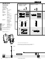
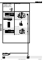
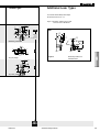
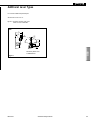
FEATURES
• EN 50041 and EN 50047 mounting and
characteristics
• Designed to IEC electrical standard for
world-wide use in guarding applications
• Positive opening operation of NC
(Normally Closed) contacts conforming
to IEC /EN 60947-5-1-3
• Available with a wide range of positive
opening contacts
• Rugged housing (Zinc Die-cast)
• Tamper resistant design uses TORX®
head security screw
• Full range of actuator heads and levers
suitable for safety applications
• Sealing up to IP 67, NEMA 1, 4, 12 & 13
• Snap action and slow action basic
switches
• International conduit sizes
• Galvanically isolated contacts
• UL listed; CSA and CE certified, BG
approved
• Red body colour for easy safety
recognition
BENEFITS
• Standard mounting and characteristics
• Globally available and accepted
• Welded NC contacts will separate – vital
security in safety applications
• Range of actuation methods for
detecting safety conditions in guarding
and machine status applications
• Wiring and body flexibility
• Suitable for inductive switching and
safety relay interfaces
• Signalling and power/safety circuits may
be different polarities or voltages
• Immediately recognisable in the
application as a safety component
GSS Series products may be used alone as Category 1 per EN 954-1 safety component. In conjunction with other safety switches and our complete range of safety
control modules, it is possible to construct comprehensive protection schemes
with Category 2, 3 or 4 compliance per EN 954-1.
Honeywell’s design experience has resulted in a brand new patented concept in
safety switching techniques. The sequential safety switch incorporates positive
opening on the downward stroke of each NC sequence point. This allows the user to
have both a warning signal and a stop signal. With this information a door can be
closed before it stops a machine or settings adjusted to stop excessive movement
thus avoiding down time.
GSS
GSS Series
Global Safety Switch
LOW ENERGY SWITCHING
In today’s demanding age of low energy controls, electromechanical switches are
frequently used to interface directly with safety relays, PLCs and other low energy
devices. To accommodate this requirement GSS offers gold plated contact versions
of the standard basic switch. This improves reliability of switching at low currents
and voltages, by protecting the contact surfaces from contamination during operation or storage prior to use.
Standard silver contacts have a disadvantage in that the contact surface may tarnish under certain environmental conditions e.g. in the presence of moisture.
Low energy basic switches are rated as follows:
Operating Voltage Ue
Operating Current Ie
1 to 50 Vac or Vdc
1 µA to 100 mA
! WARNING
MISUSE OF DOCUMENTATION
• The information presented in this product sheet (or catalogue) is for reference only. DO NOT USE this document as system
installation information.
• Complete installation, operation and maintenance information is provided in the instructions supplied with each product.
Failure to comply with these instructions could result in death or serious injury.
GSS Series
• Industrial Safety Products •
197
GSA EN 50041
Safety Metal
Standard
Snap-Action Contacts
1 NORMALLY CLOSED/
1 NORMALLY OPEN
13
14
Zb
Technical Data
up to 15 million
operations
(F.P.)
GSS
IP 67
NEMA/UL
type 1, 4, 12, 13
Operating:
Temperature
range
-25 °C to +85 °C /
-13 °F to +185 °F
Storage:
-40 °C to +85 °C /
-40 °F to +185 °F
Approvals*
IEC 60947-5-1
EN 60947-5-1
ac15 A300/A600
dc13 Q300
UL & CSA
Vibration
10 g conforming to
IEC 68-2-6
Shock
50 g conforming to
IEC 68-2-27
Terminal marking to EN 50013
56
20 mm
-3,6
22
11
12
2Y
Circuit closed
*Positive opening to IEC/EN 60947-5-1-3
Degree of
protection
21
22
21
0°
(O.P.) 26°
(R.P.) 14°
21-22
13-14
(D.T.) 12°
FP
*
OP
OT
(* )
DT = 12 mm
55°
(O.T.) 71° to 85°
21-22
13-14
32
20
-3,6 mm
(F.P.)
0°
(O.P.)
26°
(R.P.)
21-22
11-12
(D.T.)
OT
FP
*
(* )
38°
(O.T.)
71° to 85°
37,5 mm
FP
DT =
0,9 mm
37,5 mm
35,9 mm
RP
OP 35 mm
21-22
11-12
21-22
13-14
RP = 8 mm
21-22
13-14
Mechanical
life
Slow-Action Contacts
2 NORMALLY CLOSED
FP
35 mm
33 mm
33 mm
*
OT
(max.)
30,5 mm
11,3 mm
*See Standards (page 179)
15
*
OT
30,5 mm
(max.)
18,3
21-22
13-14
15
18,3
11,3 mm
*
FP
1,8 DT
Dimensions in mm / in
OT
21-22
11-12
OT
FP
21-22
13-14
*
13,2 RP
60 /
2.36
75,8 /
2.98
82 /
3.23
31,5 /
1.24
42 /
1.65
7,3 /
0.29
5,3 /
0.21
30 /
1.18
42 /
1.65
* Point from which the positive opening is assured
Conduit
Thread
A
= 1/2" NPT
C
= 20 mm
** Positive opening occurs at operating position. But to meet IEC/EN 60947-5-3
which requires a dielectric gap of 2,5 kV, positive opening is assured at*.
01
Low Energy Contacts
Ordering:
GSA
198
36
Note: See page 197
X
Example: GSA C 01 B
XX
• Industrial Safety Products •
GSS Series
Additional Lever Types
Actuator Types
For use with all Side Rotary Head Styles.
Figure 1 illustrates standard lever types which conform to EN 50041.
All dimensions are in mm / in
20 /
OP
0.79
GSA
30 ˚
20 /
0.79
67 /
2.64
52 /
2.05
A1B
ø19,1 /
0.75
Additional
levers
available
(see page 208)
85 ˚
Side Rotary, metal roller
Figure 1
Top pin plunger
FP
20 /
0.79
70 /
2.76
56 /
2.2
38,1 /
1.5
20 /
0.79
B
37,5 /
1.48
85 ˚
6,4
0.25
15 / ±2,5
OP
0.59 ±0.1
DP
Side Rotary Roller Lever
A1B Metal Roller
GSS
85 ˚
30 ˚
ø12,4 /
0.49
44 /
1.73
50,5 /
1.99
58 /
2.28
C
Top roller plunger
47
XXX
GSS Series
• Industrial Safety Products •
199
Slow-Action Contacts
3 NORMALLY CLOSED/
1 NORMALLY OPEN
BREAK BEFORE MAKE
Actuator Types
11
12
21
22
31
32
43
44
2Y
Zb
20
-3,6
32
20 /
OP
0.79
11-12
21-22
31-32
43-44
85 ˚
20 /
0.79
*
(F.P.)
30 ˚
OT
67 /
2.64
A1B
52 /
2.05
(R.P.)
0°
(D.T.)
(O.P.2) 32°
(*)
38°
(O.T.)
71° to 85°
Side Rotary, metal roller
11-12
21-22
31-32
43-44
(O.P.1) 26°
37,5 mm
35 mm
B
37,5 /
1.48
34 mm
33 mm
*
GSS
30,5 mm
11,3
Top pin plunger
OT
(MAX)
15
18,3
FP
11-12
21-22
31-32
43-44
20 /
0.79
15 / ±2,5
OP
0.59 ±0.1
DP
30 ˚
ø12,4 /
0.49
44 /
1.73
16,8
*
50,5 /
1.99
58 /
2.28
C
OT
Top roller plunger
Low Energy Contacts
47
Note: See page 197
XXX
GS
200
• Industrial Safety Products •
GSS Series
GSS
GSS Series
• Industrial Safety Products •
201
GSC EN 50047
Safety Metal
Standard
Snap-Action Contacts
1 NORMALLY CLOSED/
1 NORMALLY OPEN
13
14
Zb
Technical Data
up to 15 million
operations
GSS
IP 66
NEMA/UL
type 1, 4, 12, 13
Temperature
Operating:
range
-25 °C to +85 °C /
-13 °F to +185 °F
Storage:
-40 °C to +85 °C /
-40 °F to +185 °F
Approvals*
IEC 60947-5-1
EN 60947-5-1
ac15 A300
dc13 Q300
BG, UL & CSA
Vibration
10 g conforming to
IEC 68-2-6
Shock
50 g conforming to
IEC 68-2-27
Terminal marking to EN 50013
-4,4
15 mm
OT
DT = 9,8 mm
21-22
13-14
(O.P.)
26˚
(R.P.)
14,5˚
(D.T.)
11,5˚
(*)
54˚
(F.P.)
0˚
(D.T.)
(O.T.)
61˚ to 75˚
(O.P.)
26˚
(*)
46,5˚
(O.T.)
61˚ to 75˚
FP
OT
*
21-22
11-12
13-14
21-22
13-14
21-22
21-22
11-12
(R.P.)
FP
21 mm
18,9 mm
RP
OP 18 mm
18 mm
16,5 mm
16 mm
*
15 mm
5,3 mm
*
FP
Dimensions in mm / in
OT
(max.)
13,9
21-22
13-14
*See Standards (page 179)
*
15 mm
OT
(max.)
10,5
1,6 DT
OT
10,5
13,5
21-22
11-12
OT
FP
21-22
13-14
22 /
0.87
20 /
0.78
36,5
-4,4
0˚
FP
DT =
0,9 mm
21 mm
12
(F.P.)
RP = 5,2 mm
5,3 mm
24,75 /
0.97
*
OP
11
15 mm
43,3
21-22
13-14
FP
22
2Y
Circuit closed
*Positive opening to IEC/EN 60947-5-1-3
Degree of
protection
21
22
21
Mechanical
life
Slow-Action Contacts
2 NORMALLY CLOSED
*
8,9 RP
3/
0.12
R 2,15 /
0.08
55 /
2.16
30,5 /
1.20
14,5 /
0.57
3,5 /
0.138
30 /
1.18
* Point from which the positive opening is assured
conduit
thread
19,8 /
0.78
ø 23 /
ø 0.9
Conduit
Thread
A
= 1/2" NPT
C
= 20 mm
** Positive opening occurs at operating position. But to meet IEC/EN 60947-5-3
which requires a dielectric gap of 2,5 kV, positive opening is assured at*.
Note: Incorporates safety screws
01
Low Energy Contacts
Ordering:
GSC
202
X
Example: GSC C 01 B
36
Note: See page 197
XX
• Industrial Safety Products •
GSS Series
Additional Lever Types
Actuator Types
For use with all Side Rotary Head Styles.
All dimensions are in mm / in
Figure 2 illustrates standard lever types
which conform to EN 50047.
15 ± 3 /
0.39 ± 0.8
DT
75˚
20 /
0.79
OP
30˚
ø19 /
0.748
40 /
1.57
55 /
2.17
A1B
GSC
45 /
1.77
Additional
levers
available
(see page 208)
40 /
1.58
27 /
1.07
6/
0.24
ø19 /
0.74
75˚
75˚
Side Rotary, metal roller
46,5 /
1.83
ø 9,9 /
0.39
DT
OP
OT
(max.)
15 /
0.591
15 /
0.59
B
18 ± 0,5 /
0.709
Figure 2
Top pin plunger
10 ± 1,5 /
OP
0.394
Side Rotary Roller Lever
A1B Metal Roller
GSS
FP
21 /
0.827
DT
20 /
0.787
25 /
0.984
30˚
ø12,4 /
0.49
35 /
1.378
C
Top roller plunger
XXX
GSS Series
• Industrial Safety Products •
203
GSD EN 50047
Safety Double Insulated
Standard
Snap-Action Contacts
1 NORMALLY CLOSED/
1 NORMALLY OPEN
Slow-Action Contacts
2 NORMALLY CLOSED
13
14
Zb
Technical Data
up to 15 million
operations
GSS
IP66
NEMA/UL
type 1, 12, 13
Temperature
Operating:
range
-25 °C to +85 °C /
-13 °F to +185 °F
Storage:
-40 °C to +85 °C /
-40 °F to +185 °F
Approvals*
IEC 60947-5-1
EN 60947-5-1
ac15 A600
dc13 Q300
BG, UL & CSA
Vibration
10 g conforming to
IEC 68-2-6
Shock
50 g conforming to
IEC 68-2-27
Terminal marking to EN 50013
-4,4
43,3
21-22
13-14
FP
*
OP
OT
DT = 9,8 mm
21-22
13-14
36,5
(O.P.)
26˚
(R.P.)
14,5˚
(D.T.)
11,5˚
(*)
54˚
(F.P.)
0˚
(D.T.)
(O.T.)
61˚ to 75˚
(O.P.)
26˚
(*)
46,5˚
(O.T.)
61˚ to 75˚
21-22
11-12
FP
OT
*
21-22
11-12
13-14
(R.P.)
21-22
21-22
15 mm
-4,4
0˚
FP
DT =
0,9 mm
21 mm
12
(F.P.)
RP = 5,2 mm
FP
21 mm
18,9 mm
RP
OP 18 mm
18 mm
16,5 mm
16 mm
*
15 mm
10,5
OT
(max.)
13,9
21-22
13-14
5,3 mm
*
FP
*
15 mm
OT
(max.)
5,3 mm
*See Standards (page 179)
1,6 DT
OT
10,5
13,5
21-22
11-12
OT
FP
Dimensions in mm / in
21-22
13-14
22 /
0.87
20 /
0.78
24,75 /
0.97
15 mm
11
2Y
Circuit closed
*Positive opening to IEC/EN 60947-5-1-3
Degree of
protection
22
22
21
13-14
Mechanical
life
21
*
8,9 RP
3/
0.12
* Point from which the positive opening is assured
R 2,15 /
0.08
** Positive opening occurs at operating position. But to meet IEC/EN 60947-5-3
which requires a dielectric gap of 2,5 kV, positive opening is assured at*.
55 /
2.16
30,5 /
1.20
14,5 /
0.57
3,5 /
0.138
30 /
1.18
conduit
thread
19,8 /
0.78
ø 23 /
ø 0.9
Conduit
Thread
A
= 1/2" NPT
C
= 20 mm
Note: Incorporates safety screws
01
Low Energy Contacts
Ordering:
GSD
204
X
Example: GSD C 01 B
36
Note: See page 197
XX
• Industrial Safety Products •
GSS Series
Additional Lever Types
Actuator Types
For use with all Side Rotary Head Styles.
All dimensions are in mm / in
15 ± 3 /
0.39 ± 0.8
DT
75˚
20 /
0.79
OP
A1B
30˚
ø19 /
0.748
40 /
1.57
Figure 2 illustrates standard lever types
which conform to EN 50047.
GSD
55 /
2.17
Additional
levers
available
(see page 208)
45 /
1.77
40 /
1.58
27 /
1.07
Side Rotary, metal roller
6/
0.24
ø19 /
0.74
75˚
75˚
46,5 /
1.83
DT
OP
OT
(max.)
B
15 /
0.59
18 ± 0,5 /
0.709
15 /
0.591
Side Rotary Roller Lever
A1B Metal Roller
Top pin plunger
10 ± 1,5 /
OP
0.394
Figure 2
GSS
FP
21 /
0.827
ø 9,9 /
0.39
DT
20 /
0.787
25 /
0.984
30˚
ø12,4 /
0.49
35 /
1.378
C
Top roller plunger
XXX
GSS Series
• Industrial Safety Products •
205
GSE EN 50047 Compatible
Safety 3 Conduit Metal
Standard
Slow-Action Contacts
3 NORMALLY CLOSED/
1 NORMALLY OPEN
BREAK BEFORE MAKE
Technical Data
Mechanical
life
up to 15 million
operations
22
31
32
43
44
20
-3,6
GSS
IP66
NEMA/UL
type 1, 4, 12, 13
Temperature
Operating:
range
-25 °C to +85 °C /
-13 °F to +185 °F
Storage:
-40 °C to +85 °C /
-40 °F to +185 °F
Approvals*
IEC 60947-5-1
EN 60947-5-1
ac15 A300
dc13 Q300
BG, UL & CSA
Vibration
10 g conforming to
IEC 68-2-6
Shock
50 g conforming to
IEC 68-2-27
Terminal marking to EN 50013
2Y
75˚
A1B
30˚
OT
*
(F.P.)
15 ±3 /
OP
0.39 ±0.08
DT
32
11-12
21-22
31-32
43-44
55 /
2.17
40 /
1.57
Additional
levers
available
(see page 208)
(R.P.)
0°
(D.T.)
(O.P.2) 32°
(*)
38°
(O.T.)
71° to 85°
Side Rotary, metal roller
11-12
21-22
31-32
43-44
(O.P.1) 26°
37,5 mm
21 /
0.82
DT
FP
Top pin plunger
OT
(MAX)
15
20 /
0.79
18,3
25 /
0.98
16,8
42 /
1.65
40 /
1.57
22 /
0.87
20 /
0.79
*
15 ±3 /
OP
0.59 ±0.12
DT
30˚
11-12
21-22
31-32
43-44
Dimensions in mm / in
18 ±0,5 /
0.709 ±0.02
*
30,5 mm
*See Standards (page 179)
B
15 /
0.59
34 mm
33 mm
OP
OT
(max.)
35 mm
11,3
24,75 /
0.97
12
21
Zb
Degree of
protection
12,5 /
0.49
11
Actuator Types
35 /
1.38
C
OT
Top roller plunger
3/
0.12
* Point from which the positive opening is assured
R 2,15 /
0.08
** Positive opening occurs at operating position. But to meet IEC/EN 60947-5-3
which requires a dielectric gap of 2,5 kV, positive opening is assured at*.
60 /
2.37
13,75 /
0.54
12 /
0.47
30 /
1.18
2,5 /
0.1
52 /
2.05
57 /
2.24
4/
0.16
65 /
2.56
conduit
thread
23,8 /
0.94
ø 23 /
ø 0.9
Conduit
Thread
Note: Incorporates safety screws
A
= 1/2" NPT
C
= 20 mm
Low Energy Contacts
Ordering:
GSE
206
X
Example: GSE C 20 B
47
Note: See page 201
XX
• Industrial Safety Products •
XXX
GSS Series
Additional Lever Types
For use with all Side Rotary Head Styles.
All dimensions are in mm / in
Figure 2 illustrates standard lever types
which conform to EN 50047.
GSE
45 /
1.77
40 /
1.58
27 /
1.07
6/
0.24
ø19 /
0.74
75˚
75˚
46,5 /
1.83
Side Rotary Roller Lever
A1B Metal Roller
Figure 2
GSS Series
• Industrial Safety Products •
GSS
15 /
0.59
207
GSS
208
• Industrial Safety Products •
GSS Series