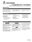
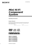
1
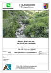
T8600D, T8601D and T8602D
Chronotherm® IV Deluxe Programmable
Thermostats
PRODUCT DATA
APPLICATION
The T8600, T8601 and T8602 Chronotherm® IV Deluxe
Programmable Thermostats provide electronic control of
24 Vac single-stage heating and cooling systems.
T8600/T8601/T8602
FEATURES AND BENEFITS
• Full seven-day program capability; different schedules
and temperature setpoints may be selected for
everyday to match the homeowner’s flexible schedule.
• Copy key makes programming easier and faster for
the installer and homeowner.
• Daylight Savings Time (DST) key for quick change in
and out of Daylight Savings Time.
• Models available with programmable fan operation for
added homeowner comfort.
• Easy temporary temperature setpoint changes for
current period, vacation hold (1 to 255 days) or
indefinite hold adds to the homeowner comfort and
energy savings.
• Frequently used keys are located by the Liquid Crystal
Display (LCD) for quick and easy access to
information.
• Attractive styling complements any decor to the
homeowner’s delight.
• Back lighting the large display makes the LCD very
easy to read.
® U.S. Registered Trademark
Copyright © 1997 Honeywell Inc. •
• All Rights Reserved
• Models available with outdoor temperature sensor
capability for homeowner convenience. The sensor is
also more accurate than a thermometer.
• Configurable features allows one model to be used to
replace many different models (less inventory, no
longer need to carry separate models to get these
features).
— °F or °C temperature display;
— Automatic or manual changeover;
— Electric or conventional heat fan operation
— Adjustable heating cycle rate.
• Minimum off time for cooling compressors and heat
pumps protects the equipment and extends the
equipment life.
• Easy installation, setup and system test saves
installer time and increases productivity.
• Self-test simplifies troubleshooting and saves time by
overriding the time delays.
• Adaptive Intelligent Recovery™ control brings the
room temperature to temperature setpoint at the
programmed time, maximizing comfort and energy
savings.
• Setpoints are permanently held in memory (no
batteries used) and retained during power outages for
increased installer and homeowner convenience.
• Power stealing, hardwired and battery powered
models available for virtually all equipment and
application needs.
• Universal Versaguard™ Thermostat guards available
for added security.
Contents
Application ............................................................................. 1
T8600/T8601/T8602 Features and Benefits ......................... 1
Specifications ........................................................................ 2
Ordering Information ............................................................. 2
Installation ............................................................................. 4
Wiring .................................................................................... 4
Settings ................................................................................. 6
Installer Setup ....................................................................... 7
Installer Self-Test ................................................................. 10
Thermostat Information ....................................................... 11
Programming ....................................................................... 11
Operation ............................................................................ 16
Troubleshooting Guide ........................................................ 17
Cross Reference ................................................................. 19
Wiring Diagrams (Fig. 15-20) .............................................. 24
68-0164-1
T8600D, T8601D AND T8602D CHRONOTHERM ® IV DELUXE PROGRAMMABLE THERMOSTATS
SPECIFICATIONS
System Current Load Ratings:
6 VA maximum at 30 Vac, 50/60 Hz.
IMPORTANT
The specifications given in this publication do not
include normal manufacturing tolerances. Therefore,
this unit might not exactly match the listed
specifications. This product is tested and calibrated
under closely controlled conditions, and some minor
differences in performance can be expected if those
conditions are changed.
Output Relay Load Rating:
See Table 2.
Temperature:
Ratings:
Operating Ambient: 40°F to 110°F (4°C to 43°C).
Shipping: -30°F to +150°F (-34°C to +65°C).
Display Accuracy: ±1°F (±0.5°C).
Thermostat Models
Setpoint:
Range:
Heating: 40°F to 90°F (4.5°C to 32°C).
Cooling: 45° F to 99°F (7°C to 35°C)
Differential: 3°F (1.5°C).
Default Settings: see Table 3.
T8600, T8601 and T8602 Thermostats provide features listed
in Table 1.
Electrical Rating (Nominal Range):
24 Vac, 50/60 Hz.
20 to 30 Vac, 50/60 Hz.
Minimum Stage Operation Time:
Minimum Off (Heat and Cool ): factory setting 5 minutes;
option 0 to 5 minutes.
Batteries:
Only T8602 models require batteries.
Humidity Ratings:
5% to 90% RH, noncondensing.
Loss of Power:
The thermostat will maintain programmed times and
temperatures for the life of the product. The clock and day
information is retained for a minimum of thirty minutes.
Clock Accuracy:
+1 minute per month.
Table 1. Thermostat Features.
System
System
Selection
Changeover
Fan
Selection
Comments
T8600 (powered by either the heating or cooling system)
D
Heat-Cool Automatic
Heat-Off-Cool-Auto On-Auto
System and fan selections are done by keyboard.
T8601 (powered by common wire to supply power)
D
Heat-Cool Automatic
Heat-Off-Cool-Auto On-Auto
System and fan selections are done by keyboard.
Heat-Off-Cool-Auto On-Auto
System and fan selections are done by keyboard.
T8602 (powered by batteries)
D
Heat-Cool Automatic
ORDERING INFORMATION
When purchasing replacement and modernization products from your TRADELINE® wholesaler or distributor, refer to the
TRADELINE® Catalog or price sheets for complete ordering number.
If you have additional questions, need further information, or would like to comment on our products or services, please write or
phone:
1. Your local Home and Building Control Sales Office (check white pages of your phone directory).
2. Home and Building Control Customer Logistics
Honeywell Inc., 1885 Douglas Drive North
Minneapolis, Minnesota 55422-4386
In Canada—Honeywell Limited/Honeywell Limitée, 35 Dynamic Drive, Scarborough, Ontario M1V 4Z9.
International Sales and Service Offices in all principal cities of the world. Manufacturing in Australia, Canada, Finland, France,
Germany, Japan, Mexico, Netherlands, Spain, Taiwan, United Kingdom, U.S.A.
68-0164—1
2
T8600D, T8601D AND T8602D CHRONOTHERM ® IV DELUXE PROGRAMMABLE THERMOSTATS
Table 2. Maximum Amps at 30 Vac.
Relay
Running (A)
Inrush (A)
Fan
0.5
2.5
Heat
1.5
3.5
Cool
1.5
7.5
Finish:
Taupe color.
Dimensions:
See Fig. 1.
Mounting Means:
The thermostat mounts on a wallplate. The wallplate mounts
horizontally on a wall or outlet box with two no. 6 x 32 screws
(included).
Table 3. Default Setpoints.
Heat
Setpoint
Cool
Setpoint
Fan
Setting
6:00 AM
70°F
(21°C)
78°F
(25.5°C)
Auto
Leave
8:00 AM
62°F
(16.5°C)
85°F
(29.5°C)
Auto
RECYCLING NOTICE
Return
6:00 PM
70°F
(21°C)
78°F
(25.5°C)
Auto
If this control is replacing a control that contains
mercury in a sealed tube, do not place your old
control in the trash.
Sleep
10:00 PM
62°F
(16.5°C)
82°F
(28°C)
Auto
Period
Time
Wake
Accessories:
C7089B Outdoor Temperature Sensors (69-1020).
Universal Versaguard™ Thermostat guards.
Contact your local waste management authority for
instructions regarding recycling and the proper
disposal of the old thermostat.
3-5/8 (92)
2-3/4 (70)
3/8 (10)
1-13/16
(46)
3-1/2
(89)
1-9/16
(40)
6-1/16 (154)
1/2
(13)
3-3/4
(95)
M10359
Fig. 1. Dimensions of thermostat in in. (mm).
3
68-0164—1
T8600D, T8601D AND T8602D CHRONOTHERM ® IV DELUXE PROGRAMMABLE THERMOSTATS
1. Position and level the wallplate (for appearance only).
The thermostat will function properly even when not
level.
2. Use a pencil to mark the mounting holes. See Fig. 3.
3. Remove the wallplate from the wall and drill two 3/16
inch holes in the wall (if drywall) as marked. For firmer
material such as plaster, drill two 7/32 inch holes.
Gently tap anchors (provided) into the drilled holes until
flush with the wall.
4. Position the wallplate over the holes, pulling wires
through the wiring opening.
5. Loosely insert the mounting screws into the holes.
6. Tighten mounting screws.
INSTALLATION
When Installing this Product...
1. Read these instructions carefully. Failure to follow the
instructions can damage the product or cause a
hazardous condition.
2. Check the ratings given in the instructions and on the
product to make sure the product is suitable for your
application.
3. Installer must be a trained, experienced service
technician.
4. After completing installation, use these instructions to
check out the product operation.
WIRING
Location
Install the thermostat about 5 ft (1.5m) above the floor in an
area with good air circulation at average temperature. See
Fig. 2.
All wiring must comply with local electrical codes and
ordinances. Follow equipment manufacturer wiring
instructions when available. Refer to Fig. 15 through 20 for
typical hookups. A letter code is located near each terminal
for identification. Refer to Table 4 for terminal designations.
Do not install the thermostat where it can be affected by:
— drafts, or dead spots behind doors and in corners.
— hot or cold air from ducts.
— radiant heat from sun or appliances.
— concealed pipes and chimneys.
— unheated (uncooled) areas such as an outside wall
behind the thermostat.
CAUTION
Disconnect power before wiring to prevent electrical
shock or equipment damage.
1. Loosen the terminal screws on the wallplate and
connect the system wires. See Fig. 4
Wallplate Installation
The thermostat can be mounted horizontally on the wall or on
a 2 in. x 4 in. wiring box. Position wallplate horizontally on the
wall or on a 2 in. x 4 in. wiring box.
YES
NO
NO
5 FEET
[1.5 METERS]
NO
M10106
Fig. 2. Typical location of thermostat.
68-0164—1
4
T8600D, T8601D AND T8602D CHRONOTHERM ® IV DELUXE PROGRAMMABLE THERMOSTATS
WALL
WIRES
THROUGH WALL
WALL
ANCHORS
(2)
FOR WRAPAROUND
INSERTION STRIP
7/16 IN. (11 MM).
FOR STRAIGHT
INSERTION STRIP
5/16 IN. (8 MM).
M4826
Fig. 4. Proper wiring technique.
MOUNTING
HOLES
Mounting Thermostat Wallplate
MOUNTING
SCREWS
The thermostat mounts on the wallplate after they are
installed.
1. Engage tabs at the top of thermostat and wallplate. See
Fig. 5.
2. Press lower edge of case to latch.
M15044
Fig. 3. Mounting the wallplate.
NOTE: To remove the thermostat from the wall, first pull out
at the bottom of the thermostat; then remove the top.
IMPORTANT
Use 18 gauge, color-coded thermostat cable for
proper wiring.
2. Securely tighten each terminal screw.
3. Push excess wire back into the hole.
4. Plug the hole with nonflammable insulation to prevent
drafts from affecting the thermostat.
Table 4. Terminal Designations and Descriptions.
Standard
Terminal
Designations
Alternate
Terminal
Designations
Typical Connection
Function
Terminal Type
B
—
Heating damper or changeover valve
Output
C
Ba, C, X1, X2
Common
Input
24V powered contact
G
F
Fan relay
Output
24V powered contact
O
R
Cooling damper or changeover valve
Output
24V powered contact
OT, OT
—
Outdoor temperature sensor (C7089B)
Input
—
R
V
24V system or heating transformer
Input
—
RC
—
24V cooling transformer
Input
—
W
H1, R3
Heating relay
Output
24V powered contact
Y
C1, M
Compressor contactor
Output
24V powered contact
a Some OEM models label the terminal for transformer common B.
5
68-0164—1
T8600D, T8601D AND T8602D CHRONOTHERM ® IV DELUXE PROGRAMMABLE THERMOSTATS
A. ENGAGE TABS AT TOP OF THERMOSTAT AND WALLPLATE.
SETTINGS
Using Thermostat Keys
The thermostat keys are used to:
• set current day and time,
• program times and setpoints for heating and cooling,
• temporarily override program temperatures,
• display present setting,
• configure Installer Setup,
• check System Test,
• display outdoor temperature (select models),
• set the system operation,
• set the fan operation.
B. PRESS LOWER EDGE OF CASE TO LATCH.
See Fig. 6 for the location of the keys.
System and Fan Settings
The system default setting is Heat and the fan default setting
is Auto. Use the System and Fan keys to change the settings.
See Fig. 7. The fan settings can be set for each program
period individually. The system selection is for all the program
periods.
M15043
Fig. 5. Mounting thermostat on wallplate.
SET WAKE TIMES
AND SETPOINTS
INCREASE TEMPERATURE
SETTING OR SCROLL
FORWARD THROUGH
INSTALLER SETUP OPTIONS
SET LEAVE TIMES
AND SETPOINTS
INCREASE TIME SETTING
OR SCROLL FORWARD
THROUGH INSTALLER SETUP
AND SYSTEM TEST
SET RETURN TIMES
AND SETPOINTS
DECREASE TEMPERATURE
SETTING OR SCROLL
BACKWARD THROUGH
INSTALLER SETUP OPTIONS
SET CURRENT
DAY AND TIME
DISPLAY INFORMATION
SUCH AS PRESENT
SETTINGS AND OUTDOOR
TEMPERATURE
RETURN TO
NORMAL
OPERATIONS
ENTER
INDEFINITE
OR TIMED
HOLD MODE
Time
Run
Program
Hold Temp
SET CURRENT OR
PROGRAM DAY
Set Current
Day/Time
Set Program
Leave
Wake
Heat/Cool
Settings
Day
Daylight
Time
Return
Sleep
System
Fan
SET SLEEP
TIMES AND
SETPOINTS
SELECT FAN
OPERATION
Copy
SELECT SYSTEM
OPERATION
CHANGE BETWEEN
DAYLIGHT SAVINGS
AND STANDARD TIME
CHANGE BETWEEN
HEATING AND COOLING
SETPOINTS
COPY ONE PROGRAMMED
DAY TO ANOTHER DAY
DECREASE TIME SETTING
OR SCROLL BACKWARD
THROUGH INSTALLER
SETUP AND SYSTEM TEST
Fig. 6. Key locations and descriptions.
68-0164—1
6
M10405A
T8600D, T8601D AND T8602D CHRONOTHERM ® IV DELUXE PROGRAMMABLE THERMOSTATS
System settings control the thermostat operation as follows:
Heat: The thermostat controls the heating.
Off: Both the heating and cooling are off.
Cool: The thermostat controls the cooling.
Auto: The thermostat automatically changes between
heating and cooling operation, depending on the indoor
temperature.
The Installer Setup is used to customize the thermostat to
specific systems. Some of the options include temperature
display, changeover and outdoor temperature display. Installer
Setup numbers are listed in Table 6. The table includes all the
configuration options and the factory-settings for the
thermostat.
A combination of key presses are required to use the Installer
Setup feature.
— To enter the Installer Setup, press and hold the
Information i key with the increase ▲ and decrease ▼
keys until the first number is displayed. All display
segments appear for approximately three seconds before
the number is displayed. See Fig. 8 and 9.
— To advance to the next Installer Setup, press the Time ▲
key.
— To change a setting, use the increase ▲ or decrease ▼
key.
— To scroll the Installer Setup numbers backwards, press
the Time ▼ key.
— To exit the Installer Setup, press Run Program.
Fan settings control the system fan as follows:
On: Fan operates continuously.
Auto: Fan operates with equipment.
Time
Run
Program
Set Current
Day/Time
Hold Temp
Day
Set Program
Wake
Leave
Daylight
Time
Return
Sleep
System
Fan
System
Heat/Cool
Settings
Copy
Fan
Set Program Start Time Set Day/Time Temporary Setting Enrg
Sav
Hold for
AM
Em Ht
Room
PM
Aux Ht
%Humid
Outdoor
MonTueWedThuFriSatSun
Heat Cool
WakeLeaveReturnSleep In Recovery
Auto Repl Batt
System
Fan
DST
On Auto
Em Heat OffCool Auto Wait
M15042
Fig. 7. Thermostat System and Fan key locations.
M10345
NOTE:
Always press the keys with your fingertip or similar
blunt tool. Sharp instruments like a pen or pencil
point can damage the keyboard.
Fig. 8. Display of all the segments of the LCD.
Temperature Settings
Refer to Table 5 for the default program. If the daytime energy
savings period is not used, press the period key (Leave or
Return) until the time is blank. The fan setting feature is
available on select thermostat models. See Programming
Section for complete instructions on changing the program.
Table 5. Default Program Settings.
Heat
Setpoint
Cool
Setpoint
Fan
Setting
6:00 AM
70°F
(21°C)
78°F
(25.5°C)
Auto
Leave
8:00 AM
62°F
(16.5°C)
85°F
(29.5°C)
Auto
Return
6:00 PM
70°F
(21°C)
78°F
(25.5°C)
Auto
Sleep
10:00 PM
62°F
(16.5°C)
82°F
(28°C)
Auto
Period
Time
Wake
INSTALLER SETUP
NUMBER DISPLAY
(COLUMN 2
OF TABLE 6)
FACTORY SETTING
OR OTHER CHOICE
DISPLAY (COLUMN 3
OR 5 OF TABLE 6)
M10404
Fig. 9. Display of Installer Setup number and setting.
CAUTION
Heat pump and electric heat systems must be
configured to 1 in Installer Setup number 2 to prevent
equipment damage caused by the system running
without the fan.
IMPORTANT
Only configurable numbers are shown on the device.
Example: If thermostat does not have a system key,
Installer Setup Number 12 will not be displayed.
Review Table 6 factory-settings and mark any
desired changes in the Actual Settings column.
When Installer Setup is complete, review the settings
to confirm that they match the system.
INSTALLER SETUP
NOTE: For most applications, the thermostat factorysettings will not need to be changed. Review the
factory settings in Table 6 and if no changes are
necessary, go to the Installer System Test section.
7
68-0164—1
T8600D, T8601D AND T8602D CHRONOTHERM ® IV DELUXE PROGRAMMABLE THERMOSTATS
Table 6. Thermostat Installer Setup Options.
Select
Installer Setup
Number (Press
Time ▲ key to
change)
Other Choices
(Press ▲ or ▼ key to change)
Factory-Setting
Display
Description
Display
—
Description
—
Actual
Setting
Not used
1
—
—
—
Fan operation a
2
0
Conventional
1
applications where
equipment controls fan
operation in heat mode
Heat pump or electric heat
applications where thermostat
controls fan operation in heat
mode
Not used
3
—
—
—
—
Heating cycle
rate
4
6
6—6 cph used for
conventional heat
1, 3 or 9
1—1 cph used for radiant floor
heat, gravity system
3—3 cph used for hot water
systems or high efficiency
furnaces
9—9 cph used for electric heat
systems
Not used
5 thru 11
—
—
—
—
System setting
adjustment
12
1
Manual changeover
0 or 2
0—Auto changeover
2—Fixed auto changeover
Adaptive
Intelligent
Recovery™
control
13
0
1
Adaptive Intelligent
Recovery™ control is
activated (system
starts early so setpoint
is reached by start of
program period)
Conventional recovery (system —
starts recovery at programmed
time)
Degree
temperature
display
14
0
Temperature is
displayed in °F
1
Temperature is displayed in °C
Not used
15
—
—
—
—
Clock format
16
0
12-hour clock format
1
24-hour clock format
Not used
17 and 18
—
—
—
—
Extended fan
operation in
heating a
19
0
No extended fan
1
operation after the call
for heat ends
Fan operation is extended 90
seconds after the call for heat
ends.
Extended fan
operation in
cooling
20
0
No extended fan
1
operation after the call
for cool ends
Fan operation is extended 90
seconds after the call for cool
ends.
Not used
21 thru 23
—
—
—
—
Outdoor
temperature
display (select
models)
24
0
No outdoor
temperature is
displayed
1
Outdoor temperature is
displayed. Needs a
C7089B1000 Outdoor Sensor
to operate
Not used
25 thru 29
—
—
—
—
Deadband
30
3
Heating and cooling
setpoints can be set
no closer than 3°F
(1.5°C)
4 thru 10
Heating and cooling setpoints
can be set no closer than the
chosen value:
4—4°F (2°C)
5—5°F (2.5°C)
6—6°F (3°C)
7—7°F (3.5°C)
8—8°F (4°C)
9—9°F (4.5°C)
10—10°F (5°C)
—
—
—
—
—
—
a Number 2 must be set to 1 to extend fan operation.
(continued)
68-0164—1
8
T8600D, T8601D AND T8602D CHRONOTHERM ® IV DELUXE PROGRAMMABLE THERMOSTATS
Table 6. Thermostat Installer Setup Options (continued).
Installer Setup
Number (Press
Time ▲ key to
change)
Select
Not used
31 and 32
Other Choices
(Press ▲ or ▼ key to change)
Factory-Setting
Display
Description
Display
Description
—
—
—
—
Minimum off time 33
for the
compressor
5
5 minute minimum off
time for the
compressor
0 thru 4
Minimum number of minutes (0
thru 5) the compressor will be
off between calls for the
compressor
Temperature
range stops in
heating
34
90
Highest setpoint
heating can be set to
40 to 89
Temperature range (1°F
increments) heating setpoint
can be set to
Temperature
range stops in
cooling
35
45
Lowest setpoint
cooling can be set to
46 to 99
Temperature range (1°F
increments) cooling setpoint
can be set to
Not used
36
—
—
—
—
Temperature
display
adjustment
37
0
No difference in
3 thru -3
displayed temperature
and actual room
temperature
Actual
Setting
—
—
1—Display adjusts to 1°F
higher than actual room
temperature
2—Display adjusts to 2°F
higher than actual room
temperature
3—Display adjusts to 3°F
higher than actual room
temperature
-1—Display adjusts to 1°F lower
than actual room temperature
-2—Display adjusts to 2°F lower
than actual room temperature
-3—Display adjusts to 3°F lower
than actual room temperature
a Number 2 must be set to 1 to extend fan operation.
IMPORTANT
Review the settings to confirm that they match the
system. Press Run Program to exit the Installer
Setup. The thermostat has saved the Installer Setup
changes and initiated a reset in order to operate with
these new settings. Be sure to set the current day
and time immediately.
2. Press Day until the current day is displayed.
NOTE: Sun=Sunday, Mon=Monday, Tue=Tuesday,
Wed=Wednesday, Thu=Thursday, Fri=Friday,
Sat=Saturday.
Set Day/Time
PM
Time
Day
Setting Current Day and Time
Run
Program
Hold Temp
Set Current
Day/Time
Wake
Leave
Heat/Cool
Settings
Day
Daylight
Time
Set Program
Return
Sleep
System
Fan
Tue
Copy
M10313
1. Press Set Current Day/Time.
3. Press Time ▲ or Time ▼ until the current time is
displayed.
NOTE: On initial power up or after an extended power
loss, 1:00 pm flashes on the display until a key
is pressed.
NOTE: Tapping the Set Current Day/Time will change
the time in one hour increments.
Time
Set Day/Time
Set Day/Time
AM
PM
Set Current
Day/Time
Time
Run
Program
Hold Temp
Set Current
Day/Time
Heat/Cool
Settings
Day
Daylight
Time
Set Program
Wake
Leave
Return
Sleep
System
Fan
Time
Mon
Run
Program
Hold Temp
Copy
Set Current
Day/Time
M10312
Wake
Heat/Cool
Settings
Day
Daylight
Time
Set Program
Leave
Return
Sleep
System
Fan
Tue
Copy
M10314
9
68-0164—1
T8600D, T8601D AND T8602D CHRONOTHERM ® IV DELUXE PROGRAMMABLE THERMOSTATS
NOTE: If the current time is Daylight Savings Time,
press Daylight Time until DST is displayed.
Set Program Start Time Set Day/Time Temporary Setting Enrg
Sav
Hold for
AM
Em Ht
Room
PM
Aux Ht
%Humid
Outdoor
Heat Cool
MonTueWedThuFriSatSun
Auto Repl Batt
WakeLeaveReturnSleep In Recovery
System
Fan
DST
On Auto
Em Heat OffCool Auto Wait
Set Day/Time
AM
Daylight
Time
Time
Run
Program
Hold Temp
Set Current
Day/Time
Wake
Leave
Heat/Cool
Settings
Day
Daylight
Time
Set Program
Return
Sleep
System
Fan
Tue
DST
Copy
M10315
M10345
4. Press Run Program.
Fig. 10. Display of all the segments of the LCD.
AM
Run
Program
Time
Run
Program
Hold Temp
Set Current
Day/Time
Heat/Cool
Settings
Day
Daylight
Time
Room
Set Program
Leave
Wake
Return
Sleep
System
Fan
Tue
Wake
System
Heat
Copy
DST
Fan
Auto
M10316
INSTALLER SYSTEM TEST
TEST NUMBER
M10257A
Fig. 11. Display of test number.
Use the Installer System Test to check the thermostat operation.
Refer to Table 7 for a list of the available system tests.
Table 7. Tests Available in Installer System Test.
To start the system test:
Test
Number
System Test Description
CAUTION
10-19
Heating equipment can be turned on and off
The minimum off time for compressors is bypassed
during the Installer System Test. Equipment damage
can occur if the compressor is cycled too quickly.
30-39
Cooling equipment can be turned on and off
40-49
Fan equipment can be turned on and off
60 0 to
60 19
Press and hold the increase ▲ and ▼ decrease keys, at the
same time, until 10 appears. All segments of the display are
displayed for three seconds before 10 appears. See Fig. 10
and 11.
70-79
Keyboard keys test
Thermostat information including date code and
software versions are displayed
Refer to Table 8 for the directions and results of the specific
tests.
NOTE: Press Time ▲ to advance to the next test and Time
▼ to go to the previous test. Press Run Program to
exit the system test.
Table 8. Installer System Test Options.
Key to Press
Test
Number
Description
Heating Equipment System Test
Time ▲
10
Enter heating equipment system test.
▲
11
Heat comes on. When Installer Setup number 2 is 1, the system fan is also energized.
▼
10
Heat and system fan turn off.
Cooling Equipment System Test
Time ▲
30
Change from heating to cooling equipment system test.
▲
31
Cool and system fan come on.
▼
30
Cool and system fan turn off.
Fan Equipment System Test
Time ▲
40
Change from cooling to fan equipment system test.
▲
41
Fan comes on.
▼
40
Fan turns off.
Key Operation System Test
Time ▲
68-0164—1
60 2
Change from fan to key operation system test.
10
T8600D, T8601D AND T8602D CHRONOTHERM ® IV DELUXE PROGRAMMABLE THERMOSTATS
NOTE: Press any key and the numbers will change on the
display. Press Time ▼ to scroll backwards and Time
▲ to scroll forward. The Run Program, Key will not
exit from this test. To exit, go to a different test and
press Run Program.
PROGRAMMING
The keyboard is located behind the thermostat cover with
three frequently used keys by the display. The thermostat
display shows day, time, program period, temperature, system
and fan operation selection.
THERMOSTAT INFORMATION
The thermostat can be set for four times and up to eight
temperatures for each day of the week (28 independent time
and 56 temperature settings). The ▲ and ▼ keys provide
quick temporary temperature changes to increase comfort.
The Hold Temp key provides energy efficient operation for
extended periods of time.
1. Press the Time ▲ key to access the thermostat
information.
Before starting the programming procedure, use Table 9 to
organize the program schedule. The factory preprogrammed
time, temperature and fan settings are shown in brackets. If a
daytime energy savings period is not used, press the period
key (Leave or Return) until the time is blank. The fan setting
feature is available on select thermostat models.
M4934
2. Press the increase ▲ key to display the production date
code. The first two large digits are the month and the
third digit is the last digit of the year (Example:
027=February 1997).
Setting the Current Day and Time
IMPORTANT
Always press the keys with your fingertip or similar
blunt tool. Sharp instruments like pens and pencil
points can damage the keyboard.
1. Press Set Current Day/Time.
M10351
NOTE: On initial power up or after an extended power
loss, 1:00 pm flashes on the display until a key
is pressed.
3. Press the increase ▲ key again to display the software
identification code. (Example: 02 = software ID code 2)
Set Day/Time
PM
Set Current
Day/Time
Time
Run
Program
Hold Temp
Set Current
Day/Time
Daylight
Time
Set Program
Wake
Leave
Heat/Cool
Settings
Day
Return
Sleep
System
Fan
Mon
Copy
M10312
M4932A
2. Press Day until the current day is displayed.
4. Press the increase ▲ key again to display the software
revision number (Example: 001=Revision number 1).
NOTE: Sun = Sunday, Mon = Monday, Tue = Tuesday,
Wed = Wednesday, Thu = Thursday, Fri =
Friday, Sat = Saturday.
Set Day/Time
PM
M10229
Time
Day
5. Press the increase ▲ key again to display the EEPROM
identification code. (Example: 314 = EEPROM ID 314)
6. Press the Run Program key to exit the system test. The
Run
Program
Hold Temp
Set Current
Day/Time
Wake
Leave
Heat/Cool
Settings
Day
Daylight
Time
Set Program
Return
Sleep
System
Fan
Tue
Copy
M10313
3. Press Time ▲ or Time ▼ until the current time is
displayed.
NOTE: Tapping the Set Current Day/Time will change
the time in one hour increments.
Time
Set Day/Time
M4933A
AM
Time
Run
Program
system test times out after five minutes without any key
presses.
Hold Temp
Set Current
Day/Time
Heat/Cool
Settings
Day
Daylight
Time
Set Program
Wake
Leave
Return
Sleep
System
Fan
Tue
Copy
M10314
11
68-0164—1
T8600D, T8601D AND T8602D CHRONOTHERM ® IV DELUXE PROGRAMMABLE THERMOSTATS
NOTE: If the current time is Daylight Savings Time,
press Daylight Time until DST is displayed.
Programming the First Day
Start by programming the Wake time and temperature (and
fan operation on select models) for any one day:
1. Press Wake.
Set Day/Time
AM
Time
Daylight
Time
Run
Program
Hold Temp
Set Program
Set Current
Day/Time
Wake
Leave
Heat/Cool
Settings
Day
Daylight
Time
Return
Sleep
System
Fan
Tue
Setting
Set Program Start Time
AM
DST
Copy
Time
Run
Program
M10315
Wake
Hold Temp
Set Current
Day/Time
Wake
Heat/Cool
Settings
Day
Daylight
Time
Set Program
Leave
Return
Sleep
System
Fan
Copy
Heat
Tue
Wake
System
Heat
Fan
Auto
4. Press Run Program.
M10317
AM
Run
Program
Time
Run
Program
Hold Temp
Set Current
Day/Time
Daylight
Time
Leave
Heat/Cool
Settings
Day
Room
Set Program
Wake
Copy
Return
Sleep
System
Fan
Tue
Wake
System
Heat
DST
Fan
Auto
M10316
Table 9. Default Time, Setpoints and Fan Settings.
Period
Start Time
Heat Setpoint
Cool Setpoint
Fan Setting
Monday
Wake
[6:00 AM]
[70°F (21°C)]
Leave
[8:00 AM]
[78°F (25.5°C)]
[Auto]
[62°F (16.5°C)]
[85°F (29.5°C)]
[Auto]
Return [6:00 PM]
[70°F (21°C)]
[78°F (25.5°C)]
[Auto]
Sleep
[62°F (16.5°C)]
[82°F (28°C)]
[Auto]
[10:00 PM]
Tuesday
Wake
[6:00 AM]
[70°F (21°C)]
[78°F (25.5°C)]
[Auto]
Leave
[8:00 AM]
[62°F (16.5°C)]
[85°F (29.5°C)]
[Auto]
Return [6:00 PM]
[70°F (21°C)]
[78°F (25.5°C)]
[Auto]
Sleep
[62°F (16.5°C)]
[82°F (28°C)]
[Auto]
[10:00 PM]
Wednesday
Wake
[6:00 AM]
[70°F (21°C)]
[78°F (25.5°C)]
[Auto]
Leave
[8:00 AM]
[62°F (16.5°C)]
[85°F (29.5°C)]
[Auto]
Return [6:00 PM]
[70°F (21°C)]
[78°F (25.5°C)]
[Auto]
Sleep
[62°F (16.5°C)]
[82°F (28°C)]
[Auto]
[10:00 PM]
Thursday
Wake
[6:00 AM]
[70°F (21°C)]
[78°F (25.5°C)]
[Auto]
Leave
[8:00 AM]
[62°F (16.5°C)]
[85°F (29.5°C)]
[Auto]
Return [6:00 PM]
[70°F (21°C)]
[78°F (25.5°C)]
[Auto]
Sleep
[10:00 PM]
[62°F (16.5°C)]
[82°F (28°C)]
[Auto]
Wake
[6:00 AM]
[70°F (21°C)]
[78°F (25.5°C)]
[Auto]
Leave
[8:00 AM]
Friday
[62°F (16.5°C)]
[85°F (29.5°C)]
[Auto]
Return [6:00 PM]
[70°F (21°C)]
[78°F (25.5°C)]
[Auto]
Sleep
[62°F (16.5°C)]
[82°F (28°C)]
[Auto]
[10:00 PM]
Saturday
Wake
[6:00 AM]
[70°F (21°C)]
[78°F (25.5°C)]
[Auto]
Leave
[8:00 AM]
[62°F (16.5°C)]
[85°F (29.5°C)]
[Auto]
Return [6:00 PM]
[70°F (21°C)]
[78°F (25.5°C)]
[Auto]
Sleep
[62°F (16.5°C)]
[82°F (28°C)]
[Auto]
[10:00 PM]
(continued)
68-0164—1
12
T8600D, T8601D AND T8602D CHRONOTHERM ® IV DELUXE PROGRAMMABLE THERMOSTATS
Table 9. Default Time, Setpoints and Fan Settings (continued).
Period
Start Time
Heat Setpoint
Cool Setpoint
Fan Setting
Sunday
Wake
[6:00 AM]
[70°F (21°C)]
[78°F (25.5°C)]
[Auto]
Leave
[8:00 AM]
[62°F (16.5°C)]
[85°F (29.5°C)]
[Auto]
Return [6:00 PM]
[70°F (21°C)]
[78°F (25.5°C)]
[Auto]
Sleep
[62°F (16.5°C)]
[82°F (28°C)]
[Auto]
[10:00 PM]
6. Press increase ▲ or decrease ▼ key until the desired
temperature setpoint is displayed.
2. Press Day until the desired day is displayed.
Setting
Set Program Start Time
AM
Time
Day
Run
Program
Hold Temp
Set Current
Day/Time
Leave
Wake
Heat/Cool
Settings
Day
Daylight
Time
Return
Sleep
System
Fan
Copy
Heat
Mon
Wake
System
Heat
Setting
Set Program Start Time
Set Program
AM
Fan
Auto
Time
Set Program
Set Current
Day/Time
Run
Program
M10318
Hold Temp
Leave
Wake
Heat/Cool
Settings
Day
Daylight
Time
Return
Sleep
System
Fan
Cool
Mon
Wake
System
Heat
Copy
Fan
Auto
M10322
3. Press Time ▲ or Time ▼ until the desired Wake time is
displayed.
7. Press Leave, Return or Sleep and repeat steps 3, 4, 5
and 5 for programming the rest of the day. The first day
is now programmed.
NOTE: The program times are in fifteen minute
intervals. (Example: 8:00, 8:15, 8:30).
IMPORTANT
Repeat steps 1 through 7 for each day of the week
that has a different program than the first day. Refer
to Copying a Day section to copy any program day to
another.
Time
Setting
Set Program Start Time
AM
Time
Run
Program
Set Current
Day/Time
Hold Temp
Set Program
Leave
Wake
Heat/Cool
Settings
Day
Daylight
Time
Return
Sleep
System
Fan
Copy
Heat
Mon
Wake
System
Heat
Fan
Auto
M10319
8. Press Run Program when all days are programmed.
4. Press increase ▲ or decrease ▼ key until the desired
Wake temperature is displayed.
AM
NOTE: The setpoint temperature range is 40 to 90°F
(7 to 31°C) for heating and 45 to 99°F (9 to
37°C) for cooling.
Run
Program
Hold Temp
Set Current
Day/Time
Leave
Heat/Cool
Settings
Daylight
Time
Leave
Heat/Cool
Settings
Day
Return
Sleep
System
Fan
Copy
Tue
Wake
System
Heat
DST
Fan
Auto
Copying a Day
Set Program
Wake
Day
Room
Set Program
Wake
M10323
AM
Run
Program
Hold Temp
Daylight
Time
Setting
Set Program Start Time
Time
Time
Set Current
Day/Time
Run
Program
Return
Sleep
System
Fan
Heat
Mon
Wake
System
Heat
Copy
NOTE: The thermostat must be in the program mode to use
the copy feature. Go to step 2 if the thermostat is
already in the program mode.
Fan
Auto
M10320
NOTE: Press Fan to modify fan operation. Auto means
the fan will run only when the heating or
cooling equipment is operating. On means the
fan will run continuously for the entire period.
1. Press Wake.
Setting
Set Program Start Time
AM
5. Press Heat/Cool Settings to switch to other system
temperature setpoint.
Time
Wake
Set Program
Set Current
Day/Time
Run
Program
Hold Temp
Leave
Wake
Heat/Cool
Settings
Day
Daylight
Time
Return
Sleep
System
Fan
Copy
Heat
Tue
Wake
System
Heat
Fan
Auto
M10324
NOTE: The program times are the same for both
heating and cooling.
2. Press Day to select the day to be copied if different
from the day displayed.
Setting
Set Program Start Time
AM
Setting
Set Program Start Time
AM
Heat/Cool
Settings
Time
Run
Program
Hold Temp
Set Current
Day/Time
Daylight
Time
Copy
Day
Set Program
Wake
Heat/Cool
Settings
Day
Time
Leave
Return
Sleep
System
Fan
Mon
Wake
System
Heat
Cool
Run
Program
Hold Temp
Set Current
Day/Time
Fan
Auto
Wake
Heat/Cool
Settings
Day
Daylight
Time
Set Program
Copy
Leave
Return
Sleep
System
Fan
Mon
Wake
System
Heat
Heat
Fan
Auto
M10325
M10321
13
68-0164—1
T8600D, T8601D AND T8602D CHRONOTHERM ® IV DELUXE PROGRAMMABLE THERMOSTATS
4. Repeat steps 2 and 3 for all the periods to be cleared.
3. Press Copy.
5. Press Run Program.
Copy
Time
Run
Program
Set Current
Day/Time
Hold Temp
Wake
Leave
Heat/Cool
Settings
Day
Daylight
Time
Set Program
Return
Sleep
System
Fan
Mon
Setting Temporary Temperatures
Copy
M10326
Changing Temperature Setting Until the Next
Program Period
4. Press Day until the day to be copied to is displayed.
Time
Day
Run
Program
Set Current
Day/Time
Hold Temp
Wake
Daylight
Time
Leave
Heat/Cool
Settings
Day
Press increase ▲ or decrease ▼ key until the desired
temperature setpoint is displayed.
Set Program
Return
Sleep
System
Fan
Mon
Wed
NOTE: If ▼ or ▲ appear under the temperature display, it
means that both the heating and cooling setpoints
are being adjusted. Tapping the key will change both
the heat and cool setpoints by one degree. Press i
after the desired setpoint is reached to check the
setpoints.
Copy
M10327
5. Press Copy.
NOTE: donE will be displayed for two seconds and
then the normal program display will be
shown.
Temporary Setting
Time
Copy
Run
Program
Time
Run
Program
Hold Temp
Set Current
Day/Time
Leave
Daylight
Time
Set Program
Wake
Leave
Return
Sleep
System
Fan
Heat
Wake
Return
Heat/Cool
Settings
Day
Set Current
Day/Time
Set Program
Wake
System
Hold Temp
Sleep
Daylight
Time
Fan
Heat/Cool
Settings
Day
Copy
M10332
Copy
M10328
6. Repeat steps 2 through 5 for all the days desired.
NOTE: The temporary temperature setting is displayed for
approximately 3 seconds. The setting is canceled
when the next period starts or when Run Program is
pressed.
7. Press Run Program.
Clearing Program Period
Changing Temperature Setting Indefinitely
NOTE: The thermostat must be in the program mode to use
the clear feature. Go to step 2 if the thermostat is
already in the program mode.
1. Press Hold Temp.
Setting
1. Press Wake, Leave, Return or Sleep.
Time
Run
Program
Hold Temp
Hold Temp
Set Current
Day/Time
Set Program
Wake
Leave
Heat/Cool
Settings
Day
Daylight
Time
Return
Sleep
System
Fan
Heat
Copy
M10333
Setting
Set Program Start Time
AM
Time
Leave
Run
Program
Set Current
Day/Time
Hold Temp
Leave
Heat/Cool
Settings
Day
Daylight
Time
Set Program
Wake
Return
Sleep
System
Fan
Copy
2. Press increase ▲ or decrease ▼ key to change the
setting, if desired.
Heat
Mon
Leave
System
Heat
Fan
Auto
M10329
2. Press Day until the desired day is displayed.
Setting
Time
Run
Program
Setting
Set Program Start Time
Hold Temp
AM
Time
Day
Run
Program
Hold Temp
Set Current
Day/Time
Daylight
Time
Wake
Daylight
Time
Leave
Heat/Cool
Settings
Day
Return
Sleep
System
Fan
Heat
Copy
M10334
Set Program
Wake
Leave
Heat/Cool
Settings
Day
Set Current
Day/Time
Set Program
Return
Sleep
System
Fan
Copy
Sat
Heat
Leave
System
Heat
Fan
Auto
3. Press Heat/Cool Settings to change between heat and
cool settings.
M10330
3. Press Leave, Return or Sleep until the start time and
temperature setting are cleared (approximately 3
seconds).
Setting
Time
Heat/Cool
Settings
NOTE: Wake cannot be cleared.
Run
Program
Hold Temp
Set Current
Day/Time
Leave
Wake
Heat/Cool
Settings
Day
Daylight
Time
Set Program
Return
Sleep
System
Fan
Cool
Copy
M10335
Time
Leave
Run
Program
Set Current
Day/Time
4. Press increase ▲ or decrease ▼ key to adjust
temperature settings.
Setting
Set Program Start Time
Set Program
Wake
Leave
Return
Sleep
System
Fan
Sat
Heat
Leave
Hold Temp
Heat/Cool
Settings
Day
Daylight
Time
Setting
Copy
M10331
Time
Run
Program
Hold Temp
Set Current
Day/Time
Wake
Heat/Cool
Settings
Day
Daylight
Time
Set Program
Leave
Return
Sleep
System
Fan
Cool
Copy
M10336
68-0164—1
14
T8600D, T8601D AND T8602D CHRONOTHERM ® IV DELUXE PROGRAMMABLE THERMOSTATS
NOTE: The display changes from the setpoint to the
room temperature after approximately 3
seconds.
NOTE: In this example, the thermostat uses the Hold setting
for eighteen days and returns to the daily programs
at the Return period start time. The temperature
settings are heating 54°F and cooling 84°F. Only the
heating temperature is used because the System is
set for Heat. The thermostat will use both the heating
and cooling temperature settings when the System
is set to Auto (select models).
5. Press Run Program to cancel the Hold and to return to
the program.
Changing Temperature Setting Until a
Designated Day and Period
IMPORTANT
If the Hold needs to be canceled before the
designated time, press Run Program to return to the
program.
1. Press Hold Temp twice.
Setting
Setting System and Fan
Hold for
Time
Hold Temp
Set Current
Day/Time
Run
Program
Set Program
Leave
Wake
Return
Heat
Sleep
The system default setting is Heat and the fan default setting
is Auto. Use the System and Fan keys to change the settings.
See Fig. 12. The fan settings can be set for each program
period individually. The system selection is for all the program
periods.
Wake
Hold Temp
Heat/Cool
Settings
Day
Daylight
Time
System
Fan
Copy
M10337
2. Press Time ▲ or Time ▼ until the desired number of
days is displayed (1 to 255 days). (Example: 18 = Hold
will override the daily programs for 18 days)
System settings control the thermostat operation as follows:
Heat: The thermostat controls the heating.
Off: Both the heating and cooling are off.
Cool: The thermostat controls the cooling.
Auto: The thermostat automatically changes between
heating and cooling operation, depending on the indoor
temperature.
Time
Setting
Hold for
Time
Run
Program
Set Program
Set Current
Day/Time
Leave
Wake
Return
Sleep
System
Fan
Heat
Wake
Hold Temp
Heat/Cool
Settings
Day
Daylight
Time
Copy
M10338
3. Press Wake, Leave, Return or Sleep to select the
period the program will start. (Example: Return =
thermostat will stop the Hold at the Return period start
time)
Fan settings control the system fan as follows:
On: Fan operates continuously.
Auto: Fan operates with equipment.
Setting
Hold for
Time
Return
Run
Program
Set Current
Day/Time
Set Program
Wake
Leave
Return
Sleep
System
Fan
Heat
Return
Hold Temp
Heat/Cool
Settings
Day
Daylight
Time
Copy
M10339
Time
4. Press increase ▲ or decrease ▼ key to adjust the
temperature setting, if desired. (Example: Heat 54° =
heating equipment will operate when the room
temperature is below 54°F)
Run
Program
Set Current
Day/Time
Hold Temp
Day
Daylight
Time
Set Program
Wake
Heat/Cool
Settings
Leave
Return
Sleep
System
Fan
System
Copy
Fan
Setting
Hold for
Time
Run
Program
Set Current
Day/Time
Set Program
Wake
Leave
Return
Sleep
System
Fan
Heat
Return
Hold Temp
Heat/Cool
Settings
Day
Daylight
Time
Copy
M15042
M10340
Fig. 12. Thermostat System and Fan key locations.
NOTE: When the System is set for Auto (select
models), both heat and cool settings are
needed. If the System is set for Heat, only the
Heat setpoint is needed or if Cool is selected,
only the Cool setpoint is needed.
Setting Temporary Fan Operation
If your thermostat has a Fan key and this feature, press Fan
until the desired fan operation is selected. This fan setting will
be in effect until the next regularly scheduled period starts.
5. Press Heat/Cool Settings to change between heat and
cool settings.
6. Press increase ▲ or decrease ▼ key to adjust the
temperature setting, if desired. (Example: Cool 84° =
cooling equipment will operate when the room
temperature is above 84°F)
15
68-0164—1
T8600D, T8601D AND T8602D CHRONOTHERM ® IV DELUXE PROGRAMMABLE THERMOSTATS
Using Daylight Savings Time Feature
THERMOSTAT
COOL SETPOINT
This feature allows you to change in and out of Daylight
Savings Time with a key press. When the Daylight Time Key is
pressed in the fall, the time will go back one hour. In the
spring, the time will go ahead one hour and the display will
show DST. See Setting the Current Day and Time section for
initial setting instructions.
PROPORTIONAL COOL
CONTROL POINT
TEMPERATURE
P+I CONTROL
POINT
NOTE: Pressing the Daylight Time Key more than once
within a five minute period will scroll you through
various time options (Example: one hour earlier or
later with or without DST). Pressing the Daylight
Time Key six times in a five minute period will return
you to your original settings.
P+I CONTROL POINT
PROPORTIONAL HEAT
CONTROL POINT
THERMOSTAT
HEAT SETPOINT
HEATING
100
AM
Daylight
Time
Time
Run
Program
Hold Temp
Set Current
Day/Time
Wake
Heat/Cool
Settings
Day
Daylight
Time
Room
Return
Sleep
System
Fan
Copy
Tue
Wake
System
Heat
0
PERCENT LOAD
50
100
M4414
Fig 13. Proportional temperature control versus P+I
temperature control.
Set Program
Leave
50
COOLING
Fan
Auto
M10341
Operation Sequence
Displaying the Outdoor Temperature
The thermostat energizes specific terminals depending what
the Fan and System are set to. The LCD will display the time,
room temperature, system and fan selection. Symbols will be
displayed when the heating, cooling or fan is energized. See
Table 10 for specific information.
If your thermostat is equipped with an outdoor sensor, you
can check the temperature at the sensor by pressing i
once.
Time
Run
Program
Hold Temp
Set Current
Day/Time
Daylight
Time
Set Program
Wake
Heat/Cool
Settings
Day
Leave
Return
Sleep
System
Fan
Outdoor
NOTE: Not all the thermostat models have all the terminals
listed in the Energize column.
Copy
M10342
Table 10. Conventional System Sequence of Operation.
OPERATION
Selection
Fan
P+I Control
System
Call
Energize
The thermostat microprocessor based control requires that
the user understands temperature control and thermostat
performance. A conventional electromechanical or electronic
thermostat does not control temperature precisely at setpoint.
Typically, there is an offset (droop) in the control point as the
system load changes. This is a phenomenon that most people
in the industry know and accept. Many factors contribute to
offset including switch differential, thermal lag, overshoot,
cycle rates and system load.
Auto
Off
None
None
On
Off
None
G
Auto
Cool
None
O
Auto
Cool or Auto
Cooling O, G and Y
Auto
Heat
None
The thermostat microprocessor simultaneously gathers,
compares and computes data. Using this data, it controls a
wide variety of functions. The special proprietary algorithm
(program) in the thermostat eliminates the factors causing
offset. This makes temperature control more accurate than
the conventional electromechanical or electronic thermostats.
The temperature control algorithm is called proportional plus
integral (P+I) control.
Auto
Heat or Auto
Heating B and W a
Auto
Auto
None
None
and
B
O or Bb
None
None
a When electric heat fan is selected, G is energized and fan
symbol is displayed.
b Based on last piece of equipment called (cooling = O or
heating = B) and Installer Setup selection.
The thermostat sensor, located on the thermostat or remote,
senses the current space temperature. The proportional error
is calculated by comparing the sensed temperature to the
programmed setpoint. The deviation from the setpoint is the
proportional error.
Equipment Protection
As part of the operational sequence, the thermostat
microprocessor also incorporates minimum off time for all
cooling stages. Using the minimum off time assures that rapid
cycling of equipment does not occur, which extends
equipment life. Minimum off times are set in the Installer
Setup.
The thermostat also determines integral error, which is a
deviation based on the length of error time. The sum of the
two errors is the (P+I) error. The cycle rate used to reach and
maintain the setpoint temperature is computed using the P+I.
The addition of the integral error is what differentiates the
thermostat from many other electronic and electromechanical
thermostats. See Fig. 13.
68-0164—1
Display
None
16
T8600D, T8601D AND T8602D CHRONOTHERM ® IV DELUXE PROGRAMMABLE THERMOSTATS
Adaptive Intelligent Recovery® calculates the recovery ramp
based on the number of degrees away from the desired
setpoint, previous equipment performance, and weather
history to initiate recovery at the optimal time to achieve the
comfort setting at the desired time.
Thermostat Operation
Startup
When power to the thermostat is turned on, a startup and
initialization program begins. The startup occurs only on initial
powerup. After total loss of power for an extended period, the
current time and day may need to be set, but the user
program is held. See Table 11 for the default values.
Once the recovery ramp is intersected, the setpoint changes
from the setback setpoint to the comfort setpoint. This change
snaps on the equipment and runs the equipment until the
setpoint is reached. If the setpoint is reached too early or too
late, the ramp is adjusted for the next days' recovery.
NOTE: Immediately following initialization, the user can
enter new setpoints to be used in place of the default
values.
Table 11. Default Time, Setpoint and Fan Settings.
Period
Time
Wake
6:00 AM
Heat
Setpoint
Cool
Setpoint
Fan
Setting
70°F
(21°C)
78°F
(25.5°C)
Auto
8:00 AM
62°F
(16.5°C)
85°F
(29.5°C)
Auto
Return
6:00 PM
70°F
(21°C)
78°F
(25.5°C)
Auto
62°F
(16.5°C)
82°F
(28°C)
Auto
10:00 PM
SETPOINT
TEMPERATURE
ACTUAL
TEMPERATURE
Leave
Sleep
70°F
60°F
WAKE
SLEEP
M6185A
HEATING MODE
Fig. 14. Temperature change in recovery.
Adaptive Intelligent Recovery® Feature
TROUBLESHOOTING GUIDE
Adaptive Intelligent Recovery® ensures that the comfort
setting is achieved at the programmed time regardless of
weather conditions. Conventional recovery, however, starts
recovery at the beginning of the programmed time period and
uses the equipment to achieve the comfort settings as soon
as possible.
Refer to Table 12 for troubleshooting information.
17
68-0164—1
T8600D, T8601D AND T8602D CHRONOTHERM ® IV DELUXE PROGRAMMABLE THERMOSTATS
Table 12. Troubleshooting Information.
Symptom
Possible Cause
Display will not
come on.
Thermostat is not being
powered.
Temperature
Room temperature display has
display is incorrect. been reconfigured.
Action
• Check for 24 Vac between R and C or W terminals.
— If missing 24 Vac:
— check if the circuit breaker is tripped—reset the circuit
breaker.
— check if the system fuse is blown—replace the fuse.
— check if the power switch on the HVAC equipment is in the
Off position—set to the On position.
— check wiring between thermostat and HVAC equipment—
replace any broken wires and tighten any loose connections.
— If 24 Vac is present, proceed with troubleshooting.
Enter Installer Setup number 37 and reconfigure the display.
Thermostat is configured for °F Enter Installer Setup number 14 and reconfigure the display.
or °C display.
Bad thermostat location.
Relocate the thermostat.
Temperature
The upper or lower temperature Check the temperature setpoints:
settings will not
limits were reached.
• Heating limits are 40 to 90°F (4.5 to 32°C)
change. (Example:
• Cooling limits are 45 to 99°F (7 to 35°C) except D model cooling
Cannot set the
limits are 48 to 99°F.
heating higher or
The setpoint temperature range Check Installer Setup numbers 34 and 35 and reconfigure the setpoint
the cooling lower.) stops were configured.
stops.
Heating will not
come on.
No power to the thermostat.
Heating will not
come on.
Thermostat minimum off time is Wait up to five minutes for the system to respond.
activated.
System selection is not set to
Heat.
• Setpoint is above room temperature.
• Check for 24 Vac between R and C or W terminals.
— If missing 24 Vac:
— check if the circuit breaker is tripped—reset the circuit
breaker.
— check if the system fuse is blown—replace the fuse.
— check if the power switch on the HVAC equipment is in the
Off position—set to the On position.
— check wiring between thermostat and HVAC equipment—
replace any broken wires and tighten any loose connections.
— If 24 Vac is present, proceed with troubleshooting.
Set system selection to Heat.
Heating setpoint is below room Check heating setpoint. Set heating setpoint to desired temperature.
temperature.
Cooling will not
come on.
No power to the thermostat.
• Setpoint is below room temperature.
• Check for 24 Vac between R or RC and C or Y terminals (D models
requires power to R at all times).
— If missing 24 Vac:
— check if the circuit breaker is tripped—reset the circuit
breaker.
— check if the system fuse is blown—replace the fuse.
— check if the power switch on the HVAC equipment is in the
Off position—set to the On position.
— check wiring between thermostat and HVAC equipment—
replace any broken wires and tighten any loose connections.
— If 24 Vac is present, proceed with troubleshooting.
Thermostat minimum off time is • Wait up to five minutes for the system to respond.
activated.
• Enter Installer Setup number 33. Reconfigure minimum off time (if
required).
System selection is not set to
Cool.
Set system selection to Cool.
Cool setpoint is above room
temperature.
Check cooling setpoint. Set cooling setpoint to desired temperature.
(continued)
68-0164—1
18
T8600D, T8601D AND T8602D CHRONOTHERM ® IV DELUXE PROGRAMMABLE THERMOSTATS
Table 12. Troubleshooting Information (continued).
Symptom
Possible Cause
Action
Heating or cooling
come on
momentarily and
shut off
Heat or cool circuit is opening
up or becoming high
impedance.
Add resistor in parallel with load or install interface relay.
System on indicator
(flame=heat,
snowflake=cool) is
displayed, but no
warm or cool air is
coming from the
registers.
Fan operation set for 0
(conventional heat) when it
should be set for 1 (electric
heat).
Enter Installer Setup number 2 and reconfigure the fan operation.
Conventional heating
equipment turns on the fan
when the furnace has
warmed up to a setpoint.
Wait a minute after seeing the on indicator and then check the registers.
Heating or cooling equipment is Verify operation of heating or cooling equipment in self-test.
not operating.
Outdoor
temperature not
displayeda
Option not activated.
Outdoor sensor is connected
Outdoor
incorrectly.
temperature
display is incorrecta Wrong sensor.
Enter Installer Setup number 24 and set to 1. Thermostat must have OT
terminals and a C7089B1000 installed.
Refer to C7089B1000 installation instructions and check wiring between
the thermostat and sensor.
Replace sensor with C7089B1000 sensor.
a Available on select models.
CROSS REFERENCE
Refer to Table 14 for thermostat cross referencing information.
All SUPER TRADELINE® Chronotherm® IV thermostats are
different from the existing Chronotherm® III devices as
summarized in Table 13.
Table 13. Differences Between Chronotherm® III Thermostats and Chronotherm® IV Thermostats.
Feature/Function
Chronotherm® III Family
Chronotherm® IV Family
Programming
5-1-1 day programming
7-day programming
Changeover
Automatic or manual changeover models
available
Automatic/manual changeover selectable
Installer configuration
Field settings made via screws on the back of
the thermostat
Field settings made through the keyboard
System switching
Mechanical switch
Keyboard entry
Fan switching
Mechanical switch
Keyboard entry
Device color
Beige or Premier White® color
Taupe or Premier White® color
19
68-0164—1
T8600D, T8601D AND T8602D CHRONOTHERM ® IV DELUXE PROGRAMMABLE THERMOSTATS
Table 14. Thermostat Cross Reference Information.
Model Number
TRADELINE®
Replacement
Description
Remarks
T8600A
One-stage heat conventional thermostat; system powered; system switch—none;
fan switch—none.
T8600A1000
Honeywell logo.
T8600D2028
Heat/cool model can be used for heat
only; system selection Heat-Off-CoolAuto; duel fuel.
T8600A1018
Canadian TRADELINE® thermostat;
Honeywell logo; degree C.
T8600D2028
Heat/cool model can be used for heat
only; system selection Heat-Off-CoolAuto; configure for °C in Installer Setup
14; duel fuel.
T8600A1034
Canadian TRADELINE® thermostat;
Honeywell logo; Premier White® color;
degree C.
T8600D2028
Heat/cool model can be used for heat
only; system selection Heat-Off-CoolAuto; configure for °C in Installer Setup
14; duel fuel.
T8600B
One-stage heat and one-stage cool conventional thermostat; system powered
T8600B1008
TRADELINE® thermostat; Honeywell logo;
system switch—HEAT-OFF; fan
switch—none.
T8600D2028
Heat/cool model can be used for heat
only; system selection Heat-Off-CoolAuto; fan selection On-Auto; duel fuel;
no positive off.
T8600B1016
TRADELINE® thermostat; Honeywell logo;
system switch—none; fan
switch—ON-AUTO.
T8600D2028
Heat/cool model can be used for heat
only; system selection Heat-Off-CoolAuto; duel fuel.
T8600C
One-stage heat and one-stage cool thermostat; system powered; system switch—HEAT-OFFCOOL; fan switch—ON-AUTO
T8600C1014
TRADELINE® thermostat; Honeywell logo;
conventional.
T8600D2028
Separate O & B terminals; duel fuel.
T8600C1030
Canadian TRADELINE® thermostat;
Honeywell logo; conventional; degree C;
O and B terminals.
T8600D2028
Configure for °C in Installer Setup 14;
duel fuel; jumper R to Rc.
T8600C1048
York logo; conventional; part no.
2ET07700124A.
T8600D2028
Separate O & B terminals; duel fuel.
T8600C1055
Canadian TRADELINE® thermostat;
Honeywell logo; conventional; degree C.
T8600D2028
Configure for °C in Installer Setup 14;
duel fuel; jumper R to Rc.
T8600C1063
Trane logo; conventional; part no.
THT0594.
T8600D2028
Separate O & B terminals; duel fuel.
T8600C1071
Trane logo; electric heat; O and B
terminals; part no. THT0595.
T8600D2028
Configure for electric heat in Installer
Setup 2; jumper R to Rc.
T8600C1089
Texfan logo; conventional.
T8600D2028
Separate O & B terminals; duel fuel.
T8600C1097
Glowcore logo; conventional; part no.
THC-3.
T8600D2028
Separate O & B terminals; duel fuel.
T8600C1105
York logo; conventional; part no. 025-27653
and 2ET0770224A.
T8600D2028
Separate O & B terminals.
T8600C1113
Canadian York thermostat; conventional;
degree C.
T8600D2028
Separate O & B terminals; configure for
°C in Installer Setup 14; duel fuel.
T8600C1121
Arcoaire logo; conventional: part no.
1506-745.
T8600D2028
Separate O & B terminals; duel fuel.
T8600C1147
Trane logo; conventional; part no.
TAYSTAT300.
T8600D2028
Separate O & B terminals; duel fuel;
jumper R to Rc.
T8600C1154
American Standard logo; conventional;
part no. ASYSTAT600.
T8600D2028
Separate O & B terminals; duel fuel;
jumper R to Rc.
T8600C1162
SUPER TRADELINE® thermostat;
Honeywell logo; duel fuel fan control; O and
B terminals.
T8600D2028
Jumper R to Rc.
(continued)
68-0164—1
20
T8600D, T8601D AND T8602D CHRONOTHERM ® IV DELUXE PROGRAMMABLE THERMOSTATS
Table 14. Thermostat Cross Reference Information. (continued)
Model Number
TRADELINE®
Replacement
Description
Remarks
T8600C1170
Carrier thermostat; conventional; part no.
HH07AX006.
T8600D2028
Separate O & B terminals; duel fuel;
jumper R to Rc.
T8600C1188
Carrier thermostat; conventional; part no.
HH641-101.
T8600D2028
Separate O & B terminals; duel fuel;
jumper R to Rc.
T8600C1196
Canadian TRADELINE® thermostat;
Honeywell logo; Premier White® color;
conventional; degree C.
T8600D2028
Separate O & B terminals; configure for
°C in Installer Setup 14; duel fuel;
jumper R to Rc.
T8600C1204
Canadian Lennox thermostat; conventional;
degree C.
T8600D2028
Separate O & B terminals; configure for
°C in Installer Setup 14; duel fuel;
jumper R to Rc.
T8600C1212
SUPER TRADELINE® thermostat;
Honeywell logo; duel fuel fan control; O and
B terminals.
T8600D2028
Jumper R to Rc; taupe color.
T8600C1220
Servel logo; Premier White® color;
conventional; Robur part no. 15471-82.
T8600D2028
Separate O & B terminals; duel fuel;
taupe color.
T8600C1238
ICP logo; Premier White® color; duel fuel
fan control; O and B terminals; part no.
HQ1149371HW.
T8600D2028
Jumper R to Rc; taupe color.
T8600C1246
ICP logo; Premier White® color; duel fuel
fan control; O and B terminals; part no.
HQ1149372HW.
T8600D2028
Jumper R to Rc; taupe color.
T8600C1253
Consolidated Industries logo; Premier
White® color; conventional; part no.
412360.
T8600D2028
Separate O & B terminals; duel fuel;
taupe color.
T8600C1279
Canadian TRADELINE® (French)
thermostat; conventional.
T8600D2028
English only keyboard; separate O & B
terminals; duel fuel.
T8600D
One-stage heat and one-stage cool conventional thermostat; system powered; automatic
changeover; system switch— HEAT-OFF-COOL-AUTO; fan switch— ON-AUTO
T8600D1004
TRADELINE® thermostat; Honeywell logo.
T8600D2028
Separate O & B terminals; duel fuel.
T8600D1012
Canadian TRADELINE® thermostat;
Honeywell logo; degree C.
T8600D2028
Separate O & B terminals; configure for
°C in Installer Setup 14; duel fuel.
T8600D1020
Energy Sensor.
T8600D2028
Separate O & B terminals; duel fuel.
T8600D1038
Canadian Carrier thermostat; degree C;
part no. HH07AT101.
T8600D2028
Separate O & B terminals; configure for
°C in Installer Setup 14; duel fuel;
T8600D1046
Trane.
T8600D2028
Separate O & B terminals; duel fuel.
T8600D1053
Heil Quaker thermostat; Honeywell logo;
part no. HQ1000776HW.
T8600D2028
Separate O & B terminals; duel fuel.
T8600D1061
Carrier.
T8600D2028
Separate O & B terminals; duel fuel.
T8600D1079
Lennox logo; part no. 27H3101.
T8600D2028
Separate O & B terminals; duel fuel.
T8600D1103
Carrier.
T8600D2028
Separate O & B terminals; duel fuel.
T8600D1111
TRADELINE® thermostat; Honeywell logo;
Premier White® color.
T8600D2028
Separate O & B terminals; duel fuel;
taupe color.
T8600D1129
Canadian TRADELINE® thermostat;
Honeywell logo; Premier White® color;
degree C.
T8600D2028
Separate O & B terminals; configure for
°C in Installer Setup 14; duel fuel.
T8600D1137
Solitaire logo; Premier White® color;
Nordyne part no. 9132400.
T8600D2028
Separate O & B terminals; duel fuel;
taupe color.
T8600D1145
Canadian Carrier thermostat; Premier
White® color; degree C; part no.
HH07AT101-W.
T8600D2028
Separate O & B terminals; configure for
°C in Installer Setup 14; duel fuel.
(continued)
21
68-0164—1
T8600D, T8601D AND T8602D CHRONOTHERM ® IV DELUXE PROGRAMMABLE THERMOSTATS
Table 14. Thermostat Cross Reference Information. (continued)
Model Number
TRADELINE®
Replacement
Description
Remarks
T8601A
One-stage conventional heat thermostat; powered direct from 24 Vac transformer
T8601A1017
Canadian TRADELINE® thermostat;
Honeywell logo; system switch—none;
fan switch—none; degree C.
T8601B
One-stage conventional heat with fan thermostat; powered direct from 24 Vac transformer
T8601B1007
TRADELINE® thermostat; Honeywell logo;
system switch—none; fan
switch—ON-AUTO .
T8601C
One-stage heat and one-stage cool conventional thermostat; powered direct from 24 Vac
transformer; system switch—HEAT-OFF-COOL; fan switch—ON-AUTO; O and B terminals
T8601C1003
TRADELINE® thermostat; Honeywell logo.
T8601D2019
Jumper R to Rc; Premier White® color.
T8601C1013
Canadian TRADELINE® thermostat;
Honeywell logo; degree C.
T8601D2019
Configure for °C in Installer Setup 14;
jumper R to Rc; Premier White® color.
T8601C1021
New Construction thermostat.
T8601D2019
Jumper R to Rc; Premier White® color.
T8601C1039
Carrier logo; part no. HH641-104.
T8601D2019
Jumper R to Rc; Premier White® color.
T8601C1047
New Construction thermostat; Premier
White® color.
T8601D2019
Jumper R to Rc.
T8601C1054
Trol-A-Temp® thermostat; Premier White®
color.
T8601D2027a
Configure manual changeover in
Installer Setup12; replacement has Oc
terminals.
T8601C1062
Trol-A-Temp® by Honeywell logo.
T8601D2027a
Configure manual changeover in
Installer Setup12; replacement has Oc
terminals; Premier White® color.
T8601D
One-stage heat and one-stage cool conventional thermostat; powered direct from 24 Vac
transformer; automatic changeover; system switch—HEAT-OFF-COOL-AUTO; fan switch—ONAUTO
T8601D1011
Canadian TRADELINE® thermostat;
Honeywell logo; degree C.
T8601D2019
Separate O & B terminals; configure for
°C in Installer Setup 14 and
changeover in 12; jumper R to Rc;
Premier White® color.
T8601D1029
New Construction thermostat.
T8601D2019
Separate O & B terminals; configure
changeover in Installer Setup 12;
jumper R to Rc; Premier White® color.
T8601D1045
Trol-A-Temp® by Honeywell thermostat;
Premier White® color.
T8601D2027a
Separate O & B terminals; replacement
has Oc terminals.
T8601D1052
New Construction thermostat; Premier
White® color.
T8601D2019
Separate O & B terminals; configure
changeover in Installer Setup 12;
jumper R to Rc.
T8601D1060
California Economizer logo; Premier
White® color.
T8601D2019
Separate O & B terminals; configure
changeover in Installer Setup 12;
jumper R to Rc.
T8601D1078
Amana logo; Premier White® color;
part no. P1213701F.
T8601D2019
Separate O & B terminals; configure
changeover in Installer Setup 12;
jumper R to Rc.
T8601D2019
T8601D2019
Heat/cool model can be used for heat
only; system selection Heat-Off-CoolAuto; configure for °C in Installer Setup
14; Premier White® color.
Heat/cool model can be used for heat
only; system selection Heat-Off-CoolAuto; jumper R to Rc for fan control;
Premier White® color.
(continued)
68-0164—1
22
T8600D, T8601D AND T8602D CHRONOTHERM ® IV DELUXE PROGRAMMABLE THERMOSTATS
Table 14. Thermostat Cross Reference Information. (continued)
Model Number
TRADELINE®
Replacement
Description
Remarks
T8602A
One-stage heat conventional thermostat; battery powered; system switch—none; fan switch—
none
T8602A1008
TRADELINE® thermostat; Honeywell logo.
T8602B
One-stage heat conventional with fan thermostat; battery powered; system switch—none; fan
switch—ON-AUTO
T8602B1006
TRADELINE® thermostat; Honeywell logo.
T8602D2000
Heat/cool model can be used for heat
only; separate O & B terminals; system
selection Heat-Off-Cool-Auto; fan
selection Auto-On; jumper R to Rc for
fan operation.
T8602B1014
TRADELINE® thermostat; Honeywell logo;
Premier White® color.
T8602D2000
Heat/cool model can be used for heat
only; separate O & B terminals; system
selection Heat-Off-Cool-Auto; fan
selection Auto-On; jumper R to Rc for
fan operation; taupe color.
T8602C
One-stage heat and one-stage cool thermostat; battery powered; system switch—HEAT-OFFCOOL; fan switch—ON-AUTO
T8602C1004
TRADELINE® thermostat; Honeywell logo.
T8602D2000
Separate O & B terminals; jumper R to
Rc.
T8602C1012
Amana logo; conventional; part no.: none.
T8602D2000
Separate O & B terminals; jumper R to
Rc.
T8602C1020
Rheem logo; conventional; part no.: none.
T8602D2000
Separate O & B terminals; jumper R to
Rc.
T8602C1046
SUPER TRADELINE® thermostat;
Honeywell logo; duel fuel fan control; O and
B terminals.
T8602D2000
T8602C1061
Trol-A-Temp® by Honeywell thermostat;
Premier White® color; conventional; O and
B terminals.
T8602C2051a
T8602C1079
Trol-A-Temp® by Honeywell thermostat;
conventional; O and B terminals.
T8602C2051a
Premier White® color.
T8602C1095
SUPER TRADELINE® thermostat;
Honeywell logo; Premier White® color; duel
fuel fan control; O and B terminals.
T8602D2000
Taupe color.
T8602C1103
Canadian TRADELINE® thermostat;
Honeywell logo; duel fuel fan control;
degree C; O and B terminals.
T8602D2000
Configure for °C in Installer Setup 14 .
T8602C1129
Universal Parts logo; Rheem part no.
41-21615-05; conventional.
T8602D2000
T8602C1137
ICP logo; duel fuel fan control; O and B
terminals; part no. HQ1149373HW.
T8602D2000
T8602C1145
ICP logo; Premier White® color; duel fuel
fan control; O and B terminals;
part no. HQ1149374HW.
T8602D2000
T8602D2000
Heat/cool model can be used for heat
only; separate O & B terminals; system
selection Heat-Off-Cool-Auto; fan
selection Auto-On.
Taupe color.
(continued)
23
68-0164—1
T8600D, T8601D AND T8602D CHRONOTHERM ® IV DELUXE PROGRAMMABLE THERMOSTATS
Table 14. Thermostat Cross Reference Information. (continued)
Model Number
TRADELINE®
Replacement
Description
Remarks
T8602D
One-stage heat and one-stage cool conventional thermostat; battery powered; automatic
changeover
T8602D1010
Trol-A-Temp® by Honeywell thermostat;
Premier White® color; system
switch—none; fan switch—none; field
terminals: W/4, R/5, Y/6.
T8602D2026a
T8602D1028
Trol-A-Temp® by Honeywell thermostat;
system switch—none; fan switch—none;
field terminals: W/4, R/5, Y/6.
T8602D2026a
CT8602C
One-stage heat and one-stage cool retail thermostat battery powered
CT8602C1001
Retail Honeywell logo; off-white color; duel
fuel fan control; system switch HEAT-OFFCOOL; fan switch ON-AUTO; separate O
and B terminals; clamshell packaging.
Premier White® color.
T8602D2000
TRADELINE® packaging.
a Trol-A-Temp® by Honeywell thermostat model.
WIRING DIAGRAMS (Fig. 15-20)
THERMOSTAT
Y
O
G
B
W
R
OT
OT
3
3
THERMOSTAT
G
W
COMPRESSOR
CONTACTOR
R
COOL
DAMPER
HEAT
RELAY
2
2
FAN
RELAY
HEAT
RELAY
OUTDOOR
TEMPERATURE
SENSOR
HEAT
DAMPER
2
FAN
RELAY
1
1
L1
(HOT)
L1
(HOT)
L2
L2
TRANSFORMER
TRANSFORMER
1 POWER SUPPLY. PROVIDE DISCONNECT MEANS AND
OVERLOAD PROTECTION AS REQUIRED.
2 NOT AVAILABLE ON T8600A MODELS.
1
POWER SUPPLY. PROVIDE DISCONNECT MEANS AND OVERLOAD
PROTECTION AS REQUIRED.
2
CAN BE USED FOR CHANGEOVER VALVE ON SINGLE-STAGE HEAT
PUMP SYSTEMS.
3
AVAILABLE ON SELECT MODELS. OT WIRES MUST HAVE A
SEPARATE CABLE FROM THE THERMOSTAT CABLE.
M10346
Fig. 15. Typical hookup of T8600 or T8602
in heat only application.
M10347
Fig. 16. Typical hookup of T8600 or T8602 in heat and cool
system with one transformer.
68-0164—1
24
T8600D, T8601D AND T8602D CHRONOTHERM ® IV DELUXE PROGRAMMABLE THERMOSTATS
THERMOSTAT
RC
Y
O
G
2
THERMOSTAT
B
W
COMPRESSOR
CONTACTOR
COOL
DAMPER
FAN
RELAY
OT
R
4
HEAT
RELAY
3
OT
C
Y
O
G
B
4
5
W
OT
R
COMPRESSOR
CONTACTOR
OUTDOOR
TEMPERATURE
SENSOR
COOL
DAMPER
FAN
RELAY
HEAT
DAMPER
OT
3
3
HEAT
RELAY
2
OUTDOOR
TEMPERATURE
SENSOR
HEAT
DAMPER
2
3
1
1
L1
(HOT)
L1
(HOT)
L1
(HOT)
L2
L2
L2
1
TRANSFORMER
HEATING
TRANSFORMER
COOLING
TRANSFORMER
1
POWER SUPPLY. PROVIDE DISCONNECT MEANS AND OVERLOAD
PROTECTION AS REQUIRED.
1
POWER SUPPLY. PROVIDE DISCONNECT MEANS AND OVERLOAD
PROTECTION AS REQUIRED.
2
JUMPER RC TERMINAL TO R TERMINAL WHEN INSTALLED ON A
ONE TRANSFORMER SYSTEM.
2
CAN BE USED FOR CHANGEOVER VALVE ON SINGLE-STAGE HEAT
PUMP SYSTEMS.
3
CAN BE USED FOR CHANGEOVER VALVE ON SINGLE-STAGE HEAT
PUMP SYSTEMS.
3
AVAILABLE ON SELECT MODELS. OT WIRES MUST HAVE A
SEPARATE CABLE FROM THE THERMOSTAT CABLE.
4
AVAILABLE ON SELECT MODELS. OT WIRES MUST HAVE A
SEPARATE CABLE FROM THE THERMOSTAT CABLE.
5
T8600D MODELS REQUIRE POWER TO R TERMINAL AT ALL TIMES.
M10353
Fig. 19. Typical hookup of T8601 in heat
and cool system with one transformer.
M10348
THERMOSTAT
Fig. 17. Typical hookup of T8600 or T8602 in heat and
cool system with two transformers.
RC
Y
O 4
G
C
B
W
R 5
OT
THERMOSTAT
C
G
W
COMPRESSOR
CONTACTOR
HEAT
RELAY
COOL
DAMPER
R
3
2
OT
4
2
FAN
RELAY
HEAT
RELAY
HEAT
DAMPER
OUTDOOR
TEMPERATURE
SENSOR
3
1
1
FAN
RELAY
L1
(HOT)
L1
(HOT)
L1
(HOT)
L2
L2
L2
1
TRANSFORMER
1 POWER SUPPLY. PROVIDE DISCONNECT MEANS AND
OVERLOAD PROTECTION AS REQUIRED.
2 NOT AVAILABLE ON "A" MODELS.
COOLING
TRANSFORMER
HEATING
TRANSFORMER
1
POWER SUPPLY. PROVIDE DISCONNECT MEANS AND OVERLOAD
PROTECTION AS REQUIRED.
2
JUMPER RC TERMINAL TO R TERMINAL WHEN INSTALLED ON A
ONE TRANSFORMER SYSTEM.
3
CAN BE USED FOR CHANGEOVER VALVE ON SINGLE-STAGE HEAT
PUMP SYSTEMS.
4
AVAILABLE ON SELECT MODELS. OT WIRES MUST HAVE A
SEPARATE CABLE FROM THE THERMOSTAT CABLE.
5
T8601D MODELS REQUIRE POWER TO R TERMINAL AT ALL TIMES.
M10357
Fig. 18. Typical hookup of T8601 in heat only application.
M10354
Fig. 20. Typical hookup of T8601 in heat
and cool system with two transformers.
25
68-0164—1
T8600D, T8601D AND T8602D CHRONOTHERM ® IV DELUXE PROGRAMMABLE THERMOSTATS
68-0164—1
26
T8600D, T8601D AND T8602D CHRONOTHERM ® IV DELUXE PROGRAMMABLE THERMOSTATS
27
68-0164—1
T8600D, T8601D AND T8602D CHRONOTHERM ® IV DELUXE PROGRAMMABLE THERMOSTATS
Home and Building Control
Honeywell Inc.
Honeywell Plaza
P.O. Box 524
Minneapolis MN 55408-0524
Home and Building Control
Honeywell Limited-Honeywell Limitée
155 Gordon Baker Road
North York, Ontario
M2H 3N7
Honeywell Latin American Region
480 Sawgrass Corporate Parkway
Suite 200
Sunrise FL 33325
Honeywell Europe S.A.
3 Avenue du Bourget
B-1140 Brussels Belgium
Honeywell Asia Pacific Inc.
Room 3213-3225
Sun Hung Kai Centre
No. 30 Harbour Road
Wanchai
Hong Kong
Helping You Control Your World®
68-0164—1 J.H. Rev. 7-97 Printed in U.S.A.
68-0164—1
Printed on recycled paper containing at
least 10% post-consumer
paper fibers.
28
www.honeywell.com/yourhome