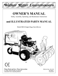
1
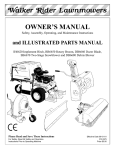
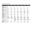
Owner's Manual
SNOW BLOWER
HS50
©1983 Honda Motor Co., Ltd. — All Rights Reserved
Thank you for purchasing a Honda snowblower.
This manual covers operation and maintenance of the HS.50 snowblower.
All information in this publication is based on the latest product information available
at the time of approval for printing.
Honda Motor Co., Ltd. reserves the right to make changes at any time without notice
and without incurring any obligation.
No part of this publication
may be reproduced without written permission.
This manual should be considered
with the snowblower when sold.
Pay special attention
to statements
a permanent
part of the snowblower
and remain
preceded by the following words:
.m
Indicates a strong possibility of severe personal injury or loss of life if
instructions are not followed.
CAUTION: Indicates a possibility of personal injury or equipment damage if instructions are not followed.
NOTE: Gives helpful information.
If a problem should arise, or if you have any questions about the snowblower consult
an authorized Honda dealer.
m
The Honda snowblower is designed to give safe and dependable service
if operated according to instructions. Read and understand the Owner’s Manual before
operating the snowblower. Failure to do so could result in personal injury or equipment damage.
1
/
CONTENTS
1. SAFETY
.......................................
2. COMPONENT IDENTIFICATION AND FUNCTION .....
...............................
Engineswitchknob
Fuel valve knob ...................................
.....................................
Chokeknob
Starter grip ......................................
Throttle lever ....................................
Shift lever .......................................
Auger clutch lever and drive clutch lever ...............
Chute crank .....................................
Chute guide .....................................
Skidplate .......................................
Height adjustment pedal ............................
3. PRE-OPERATION CHECK .........................
Fuellevel .......................................
Engine oil level ...................................
4. STARTING THE ENGINE ..........................
5. SNOWBLOWER OPERATION .......................
6. STOPPING THE ENGINE ...........................
7. MAINTENANCE .................................
., ......
Maintenance schedule .......................
Toolkit ........................................
.................................
Engineoilchange
Spark plug service .................................
Track adjustment (Track model only) .................
8. STORAGE .......................................
9. TROUBLESHOOTING .............................
10.
SPECIFICATIONS ................................
11. WARRANTY SERVICE ............................
3
6
8
8
9
9
10
10
11
12
12
13
14
15
15
16
17
20
22
23
24
25
26
27
28
29
33
‘34
35
1. SAPETY
To ensure safe operation *
Read this owner’s manual thoroughly and understand the operating procedure
before using the snowblower. Never permit anyone to operate the snowblower
without proper instructions.
*
Do not allow children to operate the snowblower. Keep children and pets away
from the area of operation.
*
Be properly dressed in winter clothing. Wear slip-proof winter boots.
*
Before operating the snowblower, inspect the area you are going to clear of snow.
Remove doormats, sleds, sticks, boards, wires and other obstacles before using the
snowblower.
*
Never clear snow from gravel road or drive as rocks are picked up and thrown.
*
Don’t use the snowblower where visibility is bad, or at nighttime under poor lighting conditions.
*
Inspect the snowblower before operating it. If it is malfunctioning, repair it before
operating it.
*
Be careful in turning the direction of the snowblower, while operating it on a slope.
Do not use the snowblower to remove snow from roofs and from steep slopes.
*
The snowblower may not stand by itself on slopes; do not leave it unattended.
3
*
Adjust the snow chute to avoid hitting bystanders, windows, etc. with thrown
snow. Stay clear of the discharge opening.
*
While operating the snowblower, always hold the handle firmly and walk. Don’t
run.
*
If people or pets suddenly appear in front of the snowblower, while it is in operation, immediately release the auger and drive clutch levers.,
*
When you hit an obstacle while operating the snowblower, stop the engine immediately and check the machinery for damage. Don’t operate a damaged machine
because you may cause an accident.
*
Before unclogging the discharge guide, turn the engine OFF.
*
Exhaust gas contains poisonous carbon monoxide.
Never run the snowblower in an enclosed area.
Be sure to provide adequate ventilation.
*
Gasoline is extremely flammable and explosive under certain conditions. Refuel in
a well ventilated area with the engine stopped.
*
When transporting the snowblower, turn the Fuel valve OFF and keep the snowblower level to prevent fuel spillage.
2. ~~MP~~NT~DENTIFI~ATI~NANDFUNCTI~N
<WHEEL
TYPES
DRIVE CLUTCH
LEVER
SPARK PLUG
CHUTE
GUIDE
FUEL cApl(
GRIP
CHUTE
AUGER
AUGER
CLUTCH
LEVER
STARTER
CHUTE
CHOKE
GRIP
CRANK
KNO
FUEL VALVE
KNOB
ENGINE
SWITCH
ENGINE OIL
DRAIN PLUG
Q TRACK TYPE >
SHIFT
LEVER
DRIVE
CLUTCH
SPARK PLUG
CHUTE
GRIP
GUIDE
AUGER
CLUTCH
I CHUTE
LEVER
CRANK
STARTER
GRIP
INE OIL
mER CAP
CHOKE
KNO
ENGINE
SWITCH
HEIGHT ADJUST
MENT PEDAL
-SKID
PLATE
ENGINE OIL
DRAIN PLUG
ENGINE SWITCH KNOB
Use the engine switch to START and STOP the engine.
ENGINE
\
I-lriif
SWITCH KNOB
FUEL VALVE KNOB
This knob opens and closes the fuel line leading from the fuel tank to the carburetor.
Make sure that the knob is positioned exactly on either the ON or OFF position.
LLL’
i ~/JE~VALVE
KNo8’l I I
I
NOTE: Before transporting snowblower be sure to turn the knob to OFF to prevent possible fuel leaks.
8
CHOKEKNOB
Use the choke knob when the engine is cold or difficult to start.
OPEN
CiiOKE
I
’
KNOti”
STARTERGRIP
Pull this grip to start the engine.
STARTER
GRIP
THROTTLE LEVER (ENGINE SPEED)
Use the throttle
position.
lever to select the engine speed. In normal operation,
ROTTLE
SHIFT LEVER
Use the shift lever to select drive speed or direction.
1: LOW SPEED
2: MEDIUM SPEED
3: HIGH SPEED
R: REVERSE
SHIFT
10
LEVER
use the “HIGH”
LEVER
AUGER CLUTCH LEVER AND DRIVE CLUTCH LEVER
Use these controls to engage the snow blowing mechanism
and/or the drive mechanism.
DRIVE
AUGER CLUTCH
LEVER
Squeeze to engage
the snow blowing
mechanism.
CLUTCH
ueese to engage the
ve mechanism.
NOTE: When both levers are squeezed, the drive clutch lever locks the auger clutch
lever down. Releasing the drive clutch lever then unlocks and releases the auger clutch
lever.
Both levers squeezed.
The auger clutch lever
remains locked down SO
long as one hand continues
to squeeze the drive clutch
lever.
11
CHUTECRANK
Use the chute crank to turn the snow discharge chute right or left.
To throw snow
to the left
CHUTE CRANK
CHUTEGUIDE
The chute guide controls the snow discharge angle.
High and far
CHUTE
12
GUIDE
HANDLE
SKID PLATE
Adjust the skid plates for the auger housing ground clearance best suited to your snow
removal conditions.
AUGER HOUSING
SNOW REMOVAL CONDITIONS
For general use
For use on uneven surfaces
For use on flat surfaces
GUARD
RECOMMENDED AUGER HOUSING
GROUND CLEARANCE
6-
lo-30
0-
8 mm (0.24-0.31
in)
mm (0.39-1.18
in)
5 mm (O-0.20
in)
NOTE: Track model only - The position of the height adjustment pedal (p. 14) also
affects auger housing ground clearance. Set the height adjustment pedal in the middle
position (II) before adjusting the skid plates.
HEIGHT ADJUSTMENT PEDAL (Track model only)
Use the pedal for adjusting the height and angle of the machine in relation
tracks.
1. Hold the handles and step on the pedal.
2. Raise or lower the machine to the desired position and release the pedal.
LOW
MIDDLE
:
:
Normal use
HIGH
:
Deep snow or for transporting the HS50
HEIGHT
PEDAL
Hard snow or fine finish
ADJUSTMENT
LOW
MIDDLE
.-
14
HIGH
to the
3.
PRE-OPERATION CHECK
FUEL LEVEL
Inspection:
Unscrew the fuel cap. Check the fuel level.
Refueling:
Use any regular grade automotive gasoline (unleaded gasoline is preferred) with a
pump octane rating of 86 or’higher. Never use an oil/gasoline mixture. Prevent dirt,
dust or water from entering the fuel tank.
CAUTION:
Gasoline substitutes are not recommended: they may be harmfull to the
fuel system components.
FUEL TANK CAPACITY: 3.5 Q (0.92 US gal, 0.77 Imp. gal.)
*
Gasoline is extremely flammable and explosive under certain conditions. Refuel
in a well ventilated area with the engine stopped.
*
Do not smoke or allow flames or sparks in the area where the snow thrower is
being refueled or where gasoline is stored.
Be careful not to spill fuel when refueling. Fuel vapor or spilled fuel may ignite.
4
Make sure the area is dry of spilled fuel before starting the engine.
*
*
DQ not overfill the tank (there should be no fuel in the filler neck). After refueling, make sure the fuel cap is closed securely.
*
Do not refuel in snow because snow will get into fuel tank and cause engine
malfunction.
15
ENGINE OIL LEVEL
Inspection:
With the snowblower on a level surface, remove the oil filler cap and check the oil
level.
If the level is low, fill to the top of the oil filler neck with the recommended oil.
Oil filler neck
OIL CAPACITY:
RECOMMENDED
-20
1
'-30
0
-20
20
-10
40
o
W’F
1
1ooc
0.7, P (0.74 US qt, 0.62 Imp. qt)
I
OIL:
Use high detergent, premium quality motor oil certified to meet or exceed U.S. automobile manufacturers’
requirements
for service classification SE or SF (Motor oils
classified SE or SF will show this designation on the container.) Select the appropriate
oil viscosity for the average temperature in your’ area, as shown in this chart. SAE
5W-30 is recommended for general, all-temperature use.
CAUTION.
* Engine oil is a major factor affecting engine’ performance and service life. Nondetergent or vegetable oils are not recommended.
* Running the engine with insufficient oil can cause serious engine damage.
16
4.
STARTING THE ENGINE
1. Turn the engine switch to the ON position.
Engine switch
2. Turn the fuel valve to the ON position.
Fuel valve
17
3. In cold weather and when the engine is cold, turn the choke knob to the CLOSE
position.
CHOKE’KNOB
4. Pull the starter grip lightly until you feel resistance, then pull briskly.
ARTER
GRIP
NOTE: Don’t allow the rope to snap back; return it gently by hand. Otherwise,
the starting mechanism might be damaged. While the engine is in operation, don’t
pull the starter grip or damage may result.
18
c
5. Let the engine warm up for several minutes. If the choke has been turned to the
CLOSE position, return it gradually to the OPEN position as the engine warms up.
I?
5.
)
SNOWBLOWER OPERATION
1. Raise the throttle lever (p. 10) to the high position for normal operation.
2. Move the shift lever (p. 10) to select the desired drive speed.
DRIVE SPEED WITH
LEVER IN THE HIGH POSITION
1 ~~~~
Wheel type
_
r
1
’
1
0.32 m/s (1.05 ft/s)
2
0.50 m/s (1.64 ft/s)
3
0.74 m/s (2.43 ft/s)
I
!
1 R 1 0.49 m/s (1.6 1 ft/s)
1
I
Track tvne
- .
11
0.21 m/s (0.69 ft/s)
0.33 m/s (1.08 ft/s)
0.48 m/s (1.57
ftls),
.
1 0.33 m/s (1.08 h/s) 1
CAUTION:
Be sure to set the shift lever into the groove. Do not change direction
while the machine is in motion.
NOTE: Low speed (1) is recommended for removing deep or hard-packed snow.
3. Track model only - Use the height adjustment pedal (p. 14) to adjust the height
and angle of the machine.
4. Adjust the chute direction (p. 12) and chute guide angle (p. 12).
5. Squeeze the auger clutch lever and drive clutch lever (p. 11) to propel the machine
and commence snow clearing.
High Altitude Operation
When operating this snow-blower at high altitude the an-fuel mixture becomes overly
rich and engine performance may be reduced and fuel consumption increased.
See your authorized HONDA dealer for high altitude adjustment.
.20
NOTE:
To move the machine without engaging the snow blowing mechanism, squeeze the
drive clutch lever only. Do this when moving the machine to or from the area to be
cleared.
l To engage the snowblowing mechanism without using the drive mechanism, squeeze
the auger clutch lever only. Do this if you wish to maneuver the machine manually
while clearing snow.
l Squeeze both levers to propel the machine and clear snow simultaneously. When
both levers are squeezed, the drive clutch lever locks the auger clutch leverdown
(p.14). The auger clutch lever remains locked down so long as one hand continues
to squeeze the drive clutch lever. Releasing the drive clutch lever then unlocks and
releases the auger clutch lever.
l If the snow is deeper than the height of the auger, move the machine back and
forth to remove snow gradually.
l For best efficiency, clear snow before it melts, refreezes and hardens.
l
AUGER CLUTCH’
LEVER
Squeeze to engage
the snow blowing
mechanism.
ueese to engage the
drive mechanism.
21
6. STOPPING THE ENGINE
1. Turn the engine switch to the OFF position.
ENGINE
2. Turn the fuel valve to the OFF position.
FUEL. VALVE
22
SWITCH
l-------
7. MAINTENANCE
---
The purpose of inspection and maintenance is to keep the snowblower
operating condition.
Inspect or service as scheduled in the table on the next page.
~j
”I
in the best
Shut off the engine before performing inspection and maintenance, and
remove the spark plug wire from the plug so the engine cannot be started. If the engine
must be run, make sure the area is well ventilated. The exhaust contains poisonous
carbon monoxide gas.
CAUTION :
l
Place the snowblower on a level surface before performing inspection and maintenance.
l
Use only genuine HONDA parts or their equivalent. The use of replacement parts
which are not of equivalent quality may damage the snowblower.
23
MAINTENANCESCHEDULE
’
Auger clutch cable
Drive clutch cable
Adjust
Track
Adjust
Auger and blower
*c3
Adjust
Check
*@I
0
0
0
Apply oil
V-Belt
Check
*o
Friction disc rubber
Check
w
Friction disc shaft
Apply oil
Nuts, bolts, fasteners
Check
Fuel tube
Replace
*0
0
Everv 3 year
* These items should be serviced by an authorized Honda dealer, unless the owner
has the proper tools and is mechanically proficient. See the Honda Shop Manual
for service information.
@ These parts may require more frequent inspection
use.
24
and replacement
under heavy
TOOL KIT
ul
(
0
Spark plug wrench
1
Wrench handle
14x10 mm wrench
14x12 mm wrench
Tool bag
25
ENGINE OIL CHANGE
Drain the oil while the engine is still warm to assure rapid and complete draining.
1. Remove the drain plug and filler cap, and drain the oil. Retighten the plug securely.
2. Fill the crankcase with the recommended oil (see page 18) and check the level.
OIL CAPACITY:
0.7 i? (0.74 US qt, 0.62 Imp qt)
DRAIN
f
-----=
-@I
AT
BOLT
b
UPPER
LIMIT
LOWER
LIMIT
OIL FILLER
CAP
HANDLE
SPARK PLUG SERVICE
Recommended
spark plug:
BR-4HS (NGK)
W 14FR-U (ND)
To ensure proper engine operation, the spark plug must be properly gapped and free
of deposits.
1. Remove the spark plug cap.
2. Use the wrench supplied in the tool kit to remove the spark plug.
3. Visually inspect the spark plug. Discard it if the insulator is cracked or chipped.
4. Measure the plug gap with a feeler gauge.
The gap should be 0.6-0.7 mm (0.024-0.028
in). Correct as necessary by bending
the side electrode.
5. Attach the plug washer. Thread the plug in by hand to prevent cross-threading.
6. Tighten a new spark plug l/2 turn with the wrench to compress the washer.
If you are reusing a plug, it should only take l/8-1/4 turn after the plug seats.
CAUTION :
The spark plug must be securely tightened. An iinproperly tightened plug can become very hot and possibly damage the generator.
l Never use a spark plug with an improper heat range.
l
0.6 0.7 mm
SPARK PLUG WRENCH
27
TRACK - ADJUSTMENT (Track model only)
ADJUSTMENT INTERVAL:
Every year, before operation.
CHECKING PROCEDURE:
Tilt the snow thrower right or left and
keep the track free. Check that the
track isn’t deflect naturally and adjust
it if necessary.
8 mm BOLT
CRAWLER
ADJUSTMENT
1. Loosen the 8 mm bolt on the rear
track wheel on each side of the
snow thrower.
2. Loosen left and right tension bolt
lock nuts, and adjust the tension bolts to obtain the correct track
deflection.
3. After adjustment, retighten the tension bolt lock nuts.
TENSION
28
BOLT
I
I
8. STORAGE
/
i-
i
Before storing the snowblower for an extended period:
1. Be sure the storage area is free of excessive humidity
2. Drain the fuel -
and dust.
m
Gasoline is extremely flammable and explosive under certain conditions.
Do not smoke or allow flames or sparks in the area.
FUEL ‘VALVE
a. Drain the fuel.
CARBURETOR
DRAIN
SCREW
b. Loosen the carburetor drain screw, and drain the gasoline into a suitable container.
Retighten the drain screw after all gasoline has been drained.
Remove the spark plug and pour three tablespoonsful
of clean motor oil into the
cylinder. Pull the starter rope slowly two or three times to distribute the oil. Reinstall
the spark plug.
Pull the starter grip until resistance is felt. This closes the valves and breaker points,
and protects them from dust and corrosion.
Apply oil to the following parts for lubrication
CHUTE
ADJUSTING
BOLT
and rust prevention.
I
-m
AUGER CLUTCH
LEVER PIVOT
31
-l
FRICTION
DISK SHAFT
1. With the fuel tank drained, turn
the chute forward and stand the
snow thrower on end as shown.
BOTTOM
2.
Remove the bottom
3. Oil the friction disk shaft.
Never oil the friction disk and dl
disk.
4. Install the bottom
COVER
cover.
cover.
FRICTION
DISK SHAFT
-..
9. TROUBLESHOOTING
--
-1
1When the engine will not start :]
1. Is there enough fuel?
2. Is the fuel valve on?
3. Is gasoline reaching the carburetor?
To check, loosen the drain screw with the fuel valve on.
If any fuel is spilled, make sure the area is dry before testing the spark
bw
plug or starting the engine. Fuel vapor or spilled fuel may ignite.
4. Is the engine switch on?
5. Is there a spark at the spark plug?
a. Remove the spark plug cap. Clean any dirt from around the spark plug base,
then remove the spark plug.
b. Install the spark plug in the plug cap.
c. Turn the engine switch on.
d. Grounding the side electrode to any engine ground, crank the engine to see if
sparks jump across the gap.
e. If there are no sparks, replace the plug.
If OK, try to start the engine according to the instructions.
6. If the engine still does not start, take the snowblower to the dealer.
IWhen the ~auger or blower will not operate:
Check the shear bolts and replace if
broken off.
Secure the shear bolts with 6 mm nuts.
Three spare shear bolts are supplied
with the HS50 snowblower.
SHEAR BOLTS
33
r
10. SPECIFICATIONS
--Engine
Model:
Maximum output:
Displacement:
Bore x stroke:
Starting method:
Ignition system:
Oil capacity:
Fuel tank capacity:
~ Spark plug:
Frame
34
HONDA engine G200
5.0 HP/l,800 r.p.m. (Cam shaft P.T.O.)
197 cm3 (12.1 cu.in)
67 x 56 cm (2.64 x 22.0 in)
Manual (Recoil starter)
Flywheel magneto type
0.7 liter (0.74 US qt, 0.62 Imp qt)
3.5 liter (0.92 US gal, 0.77 Imp gal)
BR4HS (NGK), Wl4FR-U (ND)
11. WARRANTY SERVICE
Owner
Satisfaction
Your satisfaction
and goodwill
are important
to your dealer and to us.
Normally,
any problems
with the product will be handled
by your dealer’s service department.
Sometimes,
however,
despite the best intentions of all concerned,
misunderstandings
can occur. If your problem
has not been handled to your satisfaction,
we suggest you take the following action:
l
Discuss your problem with a member of dealership
management.
Often complaints
can be quickly
resolved
at that level. If the problem
has already been reviewed
with the Service
Manager,
contact the
owner of the dealership
or the General
Manager.
l
If your problem still has not been resolved to your satisfaction,
contact the Motorcycle
and Power Products Customer
Relations
Department at the regional
office of American
Honda Motor Co., Inc. in your
area. Regional
office locations
are shown on the following
page. We
will need the following
information
in order to assist you:
-Your
-Product
-Date
name,
address,
model
and telephone
and serial
number
number
of purchase
-Dealer
name
and address
-Nature
of the problem
After reviewing
all the facts involved,
you will be advised of what action
can be taken. Please bear in mind that your problem
will likely be resolved at the dealership,
using the dealer’s
facilities,
equipment,
and
personnel,
so it is very important
that your initial
contact be with the
dealer.
Your purchase
of a Honda product
is greatly
appreciated
by both the
dealer and American
Honda Motor Co., Inc. We want to assist you in every way possible
to assure
your complete
satisfaction
with
your
purchase.
35
I
--------
Regional
Office
Locations
NORTHWEST
REGIONAL
OFFICE
(includes Alaska)
American Honda Motor Co.. Inc.
MOtOrCvCle and P ower Products
Customer Rela ,,ons Department
PO_ -Box3028
---5
Portland. Oregon 97220
Telephone: (5031255-1186
MIDWEST
REGIONAL
OFFICE
American Honda Motor Co.. Inc.
Motorcycle
and Power Products
Customer Relations Department
P.O. Box’22
Greendale. Wisconsin 53129
Telephone: (4141421.9300
\
\
WESTERN
REGIONAL
OFFICE
(includes Hawaii)
American Honda Motor Co.. Inc.
Motorcycle
and Power Products
Customer Relations Department
P.O. Box 420
Gardena. California SO247
Teleohone: 12131 604-2524
_
SOUTHWEST
REGIONAL
OFFICE
American Honda Motor Co.. Inc
Motorcycle and Power Products
Curtomar Relations Department
P.O. Bon 5406
Irving. Texas 75062
Telephone: 12141 258.688 I3
36
NORTHEAST
REGIONAL
OFFICE
American Honda Moior CO.. I~c.
Motorcycle and Power Products
Customer Relations Department
P.0 Box749
U---*-w”,
New Jersey 08067
I..““.vm.”
Telephone ,: 16091 770.1100
SOUTHEAST
REGIONAL
OFFICE
Iincludes Puerto Rico1
‘:------Honda Mot& Co., Inc.
;y;;c,;;
le end Power Products
Customer Relations Depar(ment
6684 Jim mv Carter Boulevard
N”.C,“S*
- ---, Gkrgia
30071
Telephone: 1404) 448-1992
HONDA MOTOR CO., LTD. TOKYO, JAPAN
POM53334
PN 31732010
10.0012
Printed on
Recycled Paper
PRINTED IN U.S.A.