1
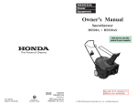
INTRODUCTION Thank you for purchasing a Honda engine. We want to help you to get the best results from your new engine and to operate it safely. This manual contains information on how to do that; please read it carefully before operating the engine. If a problem should arise, or if you have any questions about your engine, consult an authorized Honda servicing dealer. OWNER’S MANUAL GSV160 • GSV190 All information in this publication is based on the latest product information available at the time of printing. American Honda Motor Co., Inc. reserves the right to make changes at any time without notice and without incurring any obligation. No part of this publication may be reproduced without written permission. This manual should be considered a permanent part of the engine and should remain with the engine if resold. Review the instructions provided with the equipment powered by this engine for any additional information regarding engine startup, shutdown, operation, adjustments or any special maintenance instructions. SAFETY MESSAGES WARNING: Your safety and the safety of others is very important. We have provided important safety messages in this manual and on the engine. Please read these messages carefully. A safety message alerts you to potential hazards that could hurt you or others. Each safety message is preceded by a safety alert symbol and one of three words, DANGER, WARNING, or CAUTION. The engine exhaust from this product contains chemicals known to the State of California to cause cancer, birth defects or other reproductive harm. 31Z2B000 00X31-Z2B-0000 These signal words mean: IPC EM3 POM53615 40,000.2003.07 PRINTED IN U.S.A. CONTENTS INTRODUCTION. . . . . . . . . . . . . . SAFETY MESSAGES . . . . . . . . . Damage Prevention Messages . . . . . . . . . . . . . . . . . Safety Information . . . . . . . . . . COMPONENT & CONTROL LOCATION . . . . . . . . . . . . . . . . . . BEFORE OPERATION CHECKS . . . . . . . . . . . . . . . . . . . . Is Your Engine Ready To Go . . . . . . . . . . . . . . . OPERATION . . . . . . . . . . . . . . . . Safe Operating Precautions . . . . . . . . . . . . . . . . Type 1 Operation . . . . . . . . . . . Type 2 Operation . . . . . . . . . . . Type 3 Operation . . . . . . . . . . . Type 4 Operation . . . . . . . . . . . Type 5 Operation . . . . . . . . . . . Type 6 Operation . . . . . . . . . . . SERVICING YOUR ENGINE . . . . The Importance of Maintenance . . . . . . . . . . . . . . . Maintenance Safety . . . . . . . . . Safety Precautions . . . . . . . . . Maintenance Schedule . . . . . . Refueling . . . . . . . . . . . . . . . . . Fuel Recommendations . . . . . . Engine Oil . . . . . . . . . . . . . . . . . Air Cleaner . . . . . . . . . . . . . . . . Spark Plug . . . . . . . . . . . . . . . . Flywheel Brake Inspection . . . . . . . . . . . . . . . . . Spark Arrester . . . . . . . . . . . . . © 2003 American Honda Motor Co., Inc. All Rights Reserved 1 1 1 1 2 2 2 2 2 2 3 3 4 4 4 5 5 5 5 5 5 5 6 6 7 7 7 HELPFUL TIPS & SUGGESTIONS . . . . . . . . . . . . . . 8 Storing Your Engine . . . . . . . . 8 Adding A Gasoline Stabilizer To Extend Fuel Storage Life. . . . . . . . . . . . . . . . 8 Draining The Fuel Tank And Carburetor . . . . . . . . . . . . . . . . . 8 Transporting . . . . . . . . . . . . . . 9 TAKING CARE OF UNEXPECTED PROBLEMS . . . . . . . . . . . . . . . . . 9 TECHNICAL & CONSUMER INFORMATION . . . . . . . . . . . . . . . 9 Engine Serial Number And Type Location . . . . . . . . . . 9 High Altitude Operation . . . . . . . . . . . . . . . . . 9 Oxygenated Fuels . . . . . . . . . 10 Emission Control System Information . . . . . . . . . . . . . . . 10 Air Index . . . . . . . . . . . . . . . . . 11 Specifications . . . . . . . . . . . . . 11 Wiring Diagram . . . . . . . . . . . . 11 CONSUMER INFORMATION . . . 11 Honda Publications . . . . . . . . 11 U.S.A. Distributor’s Limited Warranty . . . . . . . . . . . . . . . . . 11 International Warranty . . . . . . 11 Emission Control System Warranty . . . . . . . . . . . . . . . . . 12 Distributor/Dealer Locator Information . . . . . . . . . . . . . . . 13 Customer Service Information . . . . . . . . . . . . . . . 13 DANGER You WILL be KILLED or SERIOUSLY HURT if you don't follow instructions. WARNING You CAN be KILLED or SERIOUSLY HURT if you don't follow instructions. CAUTION You CAN be HURT if you don't follow instructions. Each message tells you what the hazard is, what can happen, and what you can do to avoid or reduce injury. DAMAGE PREVENTION MESSAGES You will also see other important messages that are preceded by the word NOTICE. This word means: NOTICE Your engine or other property can be damaged if you don’t follow instructions. The purpose of these messages is to help prevent damage to your engine, other property, or the environment. SAFETY INFORMATION • Understand the operation of all controls and learn how to stop the engine quickly in case of emergency. Make sure the operator receives adequate instruction before operating the equipment. • Your engine’s exhaust contains poisonous carbon monoxide. Do not run the engine without adequate ventilation, and never run the engine indoors. • The engine and exhaust become very hot during operation. Keep the engine at least 3 feet (1 meter) away from buildings and other equipment during operation. Keep flammable materials away, and do not place anything on the engine while it is running. 1 COMPONENT & CONTROL LOCATION BEFORE OPERATION CHECKS The engine control area differs based on the engine type. Refer to the individual diagrams below to determine your engine control type when reading the Operation section and other sections in the manual. IS YOUR ENGINE READY TO GO? STARTER GRIP For your safety, and to maximize the service life of your equipment, it is very important to take a few moments before you operate the engine to check its condition. Be sure to take care of any problem you find, or have your servicing dealer correct it, before you operate the engine. FUEL FILLER CAP AIR CLEANER WARNING Improperly maintaining this engine, or failure to correct a problem before operation, can cause a malfunction in which you can be seriously hurt or killed. Always perform a preoperation inspection before each operation, and correct any problem. SPARK PLUG OIL FILLER CAP/ DIPSTICK ENGINE CONTROL AREA MUFFLER FUEL TANK Before beginning your preoperation checks, be sure the engine is level and the flywheel brake lever (type 2: throttle lever, type 4: engine stop switch) is in the STOP or OFF position. ENGINE CONTROL TYPES TYPE 1: FLYWHEEL BRAKE/ REMOTE THROTTLE Always check the following items before you start the engine: TYPE 5: MANUAL CHOKE/FIXED 1. Fuel level (see page 5). CHOKE ROD 2. Oil level (see page 6). 3. Air cleaner (see page 6). ENGINE STOP SWITCH 4. General inspection: Check for fluid leaks and loose or damaged parts. FUEL VALVE LEVER THROTTLE LEVER 5. Check the equipment powered by this engine. Review the instructions provided with the equipment powered by this engine for any precautions and procedures that should be followed before engine startup. FLYWHEEL BRAKE CONTROL LEVER TYPE 2: MANUAL CHOKE/ MANUAL THROTTLE OPERATION TYPE 6: REMOTE THROTTLE/BLADE BRAKE CLUTCH (equipment control) SAFE OPERATING PRECAUTIONS CHOKE LEVER Before operating the engine for the first time, please review the SAFETY INFORMATION section on page 1 and the BEFORE OPERATION CHECKS above. THROTTLE LEVER WARNING Carbon monoxide gas is toxic. Breathing it can cause unconsciousness and even kill you. FUEL VALVE LEVER THROTTLE FUEL VALVE LEVER LEVER Avoid any areas or actions that expose you to carbon monoxide. TYPE 3: FLYWHEEL BRAKE/REMOTE CHOKE/FIXED THROTTLE Review the instructions provided with the equipment powered by this engine for any safety precautions that should be observed with engine startup, shutdown, or operation. FLYWHEEL BRAKE CONTROL CABLE TYPE 1 (FLYWHEEL BRAKE REMOTE THROTTLE) Starting A Cold Engine CHOKE CONTROL CABLE 1. Turn the fuel valve to the ON position. OFF ON FUEL VALVE LEVER TYPE 4: AUTOMATIC CHOKE RETURN/ FIXED THROTTLE CHOKE LEVER FUEL VALVE FLYWHEEL BRAKE CONTROL CABLE FUEL VALVE LEVER 2 2. Move the throttle control (see equipment manual) to move the choke/throttle lever to the CHOKE position. SLOW TYPE 2 (MANUAL CHOKE CONTROL/ MANUAL THROTTLE CONTROL) FAST Starting A Cold Engine CHOKE 1. Turn the fuel valve to the ON position (see page 2). CHOKE/ THROTTLE LEVER 2. Move the choke lever to the ON position. 3. Move the throttle lever to the FAST position. STOP 3. Move the flywheel brake control (see equipment manual) to move the flywheel brake lever to the RUN position. SLOW FAST CHOKE LEVER OFF FLYWHEEL BRAKE LEVER FUEL VALVE THROTTLE LEVER ON ON 4. Pull the starter grip lightly until resistance is felt, then pull briskly (see page 3). 5. If the choke was used to start the engine, move the choke lever to the OFF position as soon as the engine warms up enough to run smoothly without use of the choke. 4. Pull the starter grip lightly until resistance is felt, then pull briskly. 6. Position the throttle lever for the desired engine speed. For best engine performance, it is recommended the engine be operated with the throttle in the FAST (or high) position. NOTICE Do not allow the starter grip to snap back against the engine. Return it gently to prevent damage to the starter. 5. If the choke was used to start the engine, move the choke/throttle lever to the FAST (or high) position as soon as the engine warms up enough to run smoothly without use of the choke. STARTER GRIP Starting A Warm Engine: 1. Move the throttle lever to the FAST position. FAST 2. Pull the starter grip lightly until resistance is felt, then pull briskly (see page 3). CHOKE CHOKE/ THROTTLE LEVER Stopping The Engine 1. Move the throttle lever to the SLOW position. 2. Move the throttle lever to the STOP position. Throttle Setting 3. Turn the fuel valve to the OFF position (see page 2). Position the throttle control for the desired engine speed. For best engine performance, it is recommended the engine be operated with the throttle in the FAST (or high) position. TYPE 3 (FLYWHEEL BRAKE/REMOTE CHOKE/PRESET THROTTLE) Starting A Warm Engine: 1. Turn the fuel valve to the ON position (see page 2). Starting A Cold Engine 1. Place the choke/throttle lever in the FAST position. 2. Move the choke control cable (see equipment manual) so that the choke arm moves to the choke ON position. 2. Move the flywheel brake lever to the RUN position. 3. Pull the starter grip lightly until resistance is felt, then pull briskly. Stopping The Engine SLOW 1. Move the choke/throttle control to the SLOW position. FAST CHOKE CONTROL CABLE FUEL VALVE ON 4. Pull the starter grip lightly until resistance is felt, then pull briskly (see page 3). 5. If the choke was used to start the engine, move the choke control cable so that the choke arm moves to the OFF position as soon as the engine warms up enough to run smoothly without use of the choke. FLYWHEEL BRAKE LEVER 3. Turn the fuel valve to the OFF position (see page 2). FLYWHEEL BRAKE LEVER STOP RUN 6. The engine speed is preset on this type. 3 ON CHOKE ARM 3. Move the flywheel brake lever to the RUN position. THROTTLE LEVER 2. Release the flywheel brake lever to stop the engine. OFF Starting A Warm Engine Starting A Warm Engine 1. Move the flywheel brake lever to the RUN position. 1. Turn the engine stop switch to the ON position. 2. Pull the starter grip lightly until resistance is felt, then pull briskly (see page 3). 2. Pull the starter grip lightly until resistance is felt, then pull briskly (see page 3). Stopping The Engine Stopping The Engine 1. Release the flywheel brake lever to stop the engine. 1. Move the engine switch to the OFF position. 2. Turn the fuel valve to the OFF position (see page 2). 2. Turn the fuel valve to the OFF position (see page 2). TYPE 4 (AUTOMATIC CHOKE RETURN/PRESET THROTTLE) TYPE 6 (REMOTE THROTTLE/BLADE BRAKE CLUTCH) Starting A Cold Engine 1. Turn the fuel valve to the ON position (see page 2). Starting A Cold Engine OFF 1. Turn the fuel valve to the ON position (see page 2). 2. Move the choke/ throttle/stop lever to the CHOKE position. 2. Move the choke lever to the choke position (). CHOKE LEVER 3. Move the flywheel brake lever to the RUN position. 4. Pull the starter grip lightly until resistance is felt, then pull briskly (see page 3). Make sure the blade brake clutch control lever is disengaged (see equipment manual). ON STOP RUN FLYWHEEL BRAKE LEVER STOP SLOW FAST CHOKE CHOKE/ THROTTLE/ STOP LEVER 3. Pull the starter grip lightly until resistance is felt, then pull briskly (see page 3). Begin pulling the recoil starter as soon as you move the flywheel brake lever to the RUN position. The choke lever automatically begins moving to the OFF position when the flywheel brake lever is moved to the RUN position. 4. As soon as the engine starts, slowly move the choke/ throttle/stop lever to the FAST position. 5. If the engine does not start within several consecutive pulls of the recoil starter, release the flywheel brake lever and move the choke lever to the ON position. 6. Move the flywheel brake lever to the RUN position and immediately begin operating the recoil starter. 5. Allow the engine to warm to operating temperature, then engage the blade brake clutch control lever (see equipment manual). 7. The throttle is preset on this type. Starting A Warm Engine Starting A Warm Engine 1. Place the choke/throttle/stop lever in the FAST position. 1. Move the flywheel brake lever to the brake OFF position. Make sure the blade brake clutch control lever is disengaged (see equipment manual). 2. Pull the starter grip lightly until resistance is felt, then pull briskly (see page 3). Stopping The Engine 2. Pull the starter grip lightly until resistance is felt, then pull briskly (see page 3). 1. Release the flywheel brake lever to activate the flywheel brake and stop the engine. Throttle Setting TYPE 5 (MANUAL CHOKE CONTROL/PRESET THROTTLE) Position the choke/throttle/stop lever for the desired engine speed. For best engine performance, it is recommended the engine be operated with the choke/throttle/stop lever in the FAST (or high) position. Starting A Cold Engine Stopping The Engine 2. Turn the fuel valve to the OFF position (see page 2). ENGINE STOP SWITCH 1. Turn the fuel valve to the ON position (see page 2). 2. Pull the choke rod to the ON position. 3. Turn the engine stop switch to the ON position. 1. Disengage the blade brake clutch control lever (see equipment manual). CHOKE ROD 2. Move the choke/throttle/stop lever to the SLOW position and allow the engine to idle for a few seconds. OFF ON 3. Move the choke/throttle/stop lever to the STOP position. ON 4. Turn the fuel valve OFF (see page 2). 4. Pull the starter grip lightly until resistance is felt, then pull briskly (see page 3). For best engine performance, it is recommended the engine be operated with the throttle lever in the FAST (or high) position. 5. If the choke was used to start the engine, move the choke rod to the OFF position as soon as the engine warms up enough to run smoothly without use of the choke. 6. The engine speed is preset on this type. 4 SERVICING YOUR ENGINE MAINTENANCE SCHEDULE THE IMPORTANCE OF MAINTENANCE REGULAR SERVICE PERIOD (3) Good maintenance is essential for safe, economical and trouble-free operation. It will also help reduce pollution. Perform at every indicated Item month or operating hour interval, which ever comes first. WARNING Engine oil Improper maintenance, or failure to correct a problem before operation, can cause a malfunction in which you can be seriously hurt or killed. Air cleaner Always follow the inspection and maintenance recommendations and schedules in this owner’s manual. Flywheel brake operation First Every 3 Every 6 Before month months months or or or each 100 50 20 use hours hours hours Check level O Change O To help you properly care for your engine, the following pages include a maintenance schedule, routine inspection procedures, and simple maintenance procedures using basic hand tools. Other service tasks that are more difficult, or require special tools, are best handled by professionals and are normally performed by a Honda technician or other qualified mechanic. Spark plug Spark arrester (optional parts) The maintenance schedule applies to normal operating conditions. If you operate your engine under severe conditions, such as sustained high-load or high-temperature operation, or use in unusually wet or dusty conditions, consult your servicing dealer for recommendations applicable to your individual needs and use. Maintenance, replacement, or repair of the emission control devices and systems may be performed by any engine repair establishment or individual, using parts that are “certified” to EPA standards. 6 O Clean O (1) 6 Replace Flywheel brake shoe Page 6 O Check Every year or 200 hours O (*) Check-adjust O Check O (2) Check-adjust † O (2) 7 O Replace O Clean O 7 7 Idle speed Check-adjust O(2) Shop manual Valve clearance Check-Adjust O(2) Shop manual Combustion chamber Clean O(2) Shop manual Fuel tank and filter Clean Fuel tube Check Every 250 hours (2) — Every 2 years (Replace if necessary) (2) Shop manual (*) Replace paper element type only. (1) Service more frequently when used in dusty areas. (2) These items should be serviced by an authorized Honda servicing dealer, unless you have the proper tools and are mechanically proficient. Refer to the Honda shop manual for service procedures. (3) For commercial use, log hours of operation to determine proper maintenance intervals. † See your equipment manual. MAINTENANCE SAFETY Some of the most important safety precautions follow. However, we cannot warn you of every conceivable hazard that can arise in performing maintenance. Only you can decide whether or not you should perform a given task. REFUELING WARNING Use unleaded gasoline with a pump octane rating of 86 or higher. This engine is certified to operate on unleaded gasoline. Unleaded gasoline produces fewer engine and spark plug deposits and extends exhaust system life. Failure to properly follow maintenance instructions and precautions can cause you to be seriously hurt or killed. Always follow the procedures and precautions in this owner’s manual. WARNING Gasoline is highly flammable and explosive, and you can be burned or seriously injured when refueling. SAFETY PRECAUTIONS • Make sure the engine is off before you begin any maintenance or repairs. This will eliminate several potential hazards: – Carbon monoxide poisoning from engine exhaust. Be sure there is adequate ventilation whenever you operate the engine. – Burns from hot parts. Let the engine and exhaust system cool before touching. – Injury from moving parts. Do not run the engine unless instructed to do so. • Read the instructions before you begin, and make sure you have the tools and skills required. • To reduce the possibility of fire or explosion, be careful when working around gasoline. Use only a nonflammable solvent, not gasoline, to clean parts. Keep cigarettes, sparks and flames away from all fuel related parts. Remember that an authorized Honda servicing dealer knows your engine best and is fully equipped to maintain and repair it. To ensure the best quality and reliability, use only new genuine Honda parts or their equivalents for repair and replacement. • Stop engine and keep heat, sparks, and flame away. • Refuel only outdoors. • Wipe up spills immediately. NOTICE Fuel can damage paint and some types of plastic. Be careful not to spill fuel when filling your fuel tank. Damage caused by spilled fuel is not covered under the Distributor’s Limited Warranty (see page 11). Never use stale or contaminated gasoline or oil/gasoline mixture. Avoid getting dirt or water in the fuel tank. Adding Fuel 1. Remove the fuel tank cap. 2. Add fuel to the bottom of the FUEL LEVEL MARK fuel level limit in the neck of the fuel tank. Do not overfill. MAXIMUM FUEL LEVEL Wipe up spilled fuel before starting the engine. Fuel tank capacity: 0.29 gal (1.1 ) 5 ENGINE OIL AIR CLEANER Recommended Oil A dirty air cleaner will restrict air flow to the carburetor and cause poor engine performance. Inspect the filter elements each time the engine is operated. You will need to clean the filter elements more frequently if you operate the engine in very dusty areas. Use 4-stroke motor oil that meets or exceeds the requirements for API service classification SH, SJ, or equivalent. Always check the API service label on the oil container to be sure it includes the letters SH, SJ, or equivalent. NOTICE Operating the engine without a filter, or with a damaged filter, will allow dirt to enter the engine, causing rapid engine wear. This type of damage is not covered under the Distributor’s Limited Warranty (see page 11). SAE 10W-30 is recommended for general use. Other viscosities shown in the chart may be used when the average temperature in your area is within the indicated range. Inspection 1. Press the latch tabs on the top of the air cleaner cover, and remove the cover. Oil Level Check 1. Check the oil with the engine stopped and level. 2. Remove the foam element from the air cleaner cover. 2. Remove the oil filler cap/dipstick and wipe it clean. 3. Remove the screen grid from the paper element. 3. Insert the oil filler cap/dipstick into the oil filler neck as shown, then remove it to check the oil level. Do not screw it in. 4. Check both elements to be sure they are clean and in good condition. 4. If the oil level is near or below the lower limit mark on the dipstick, remove the oil filler cap/dipstick, and fill with the recommended oil to the upper limit mark. Do not overfill. 5. Reinstall the screen grid over the paper element. Make sure that the screen grid completely surrounds the paper pleats 6. Reinstall the foam element in the air cleaner cover. 5. Reinstall the oil filler cap/dipstick. OIL FILLER CAP/DIPSTICK 7. Set the paper element and screen grid in the air cleaner body then install the air cleaner cover. AIR DUCT OIL FILLER NECK PAPER FILTER SCREEN GRID UPPER LIMIT FOAM FILTER LOWER LIMIT LATCH TABS Oil Change Drain the engine oil when the engine is warm. Warm oil drains quickly and completely. OIL FILLER NECK LOWER TABS OIL FILLER CAP/ DIPSTICK AIR CLEANER BODY UPPER LIMIT LOWER LIMIT AIR CLEANER COVER Cleaning 1. Turn the fuel valve to the OFF position to reduce the possibility of fuel leakage (see page 2). 1. Paper Element: Tap the paper element several times on a hard surface to remove dirt, or blow compressed air [not exceeding 30 psi (207 kPa, 2.1 kg/cm²)] through the filter from the clean side that faces the engine. Never try to brush off dirt. Brushing will force dirt into the fibers. 2. Place a suitable container next to the engine to catch the used oil. 3. Remove the oil filler cap/dipstick and drain the oil into the container by tipping the engine toward the oil filler neck. Please dispose of used motor oil in a manner that is compatible with the environment. We suggest you take used oil in a sealed container to your local recycling center or service station for reclamation. Do not throw it in the trash or pour it on the ground or down a drain. 2. Foam Element: Wash the element in a solution of household detergent and warm water, then rinse thoroughly, or wash in nonflammable or high flash point solvent. Allow the element to dry thoroughly. Soak the element in clean engine oil and squeeze out the excess oil. The engine will smoke during initial start-up if too much oil is left in the foam, or the oil could saturate the paper element making the engine inoperable. 4. With the engine in a level position, fill to the upper limit mark on the dipstick with the recommended oil (see above). Engine Oil Capacity: 0.58 qt (0.55 ) 3. Wipe dirt from the air cleaner body and cover using a moist rag. Be careful to prevent dirt from entering the air duct that leads to the carburetor. NOTICE Running the engine with a low oil level can cause engine damage. 5. Reinstall the oil filler cap/dipstick securely. 6 SPARK PLUG FLYWHEEL BRAKE INSPECTION Recommended Spark Plug: NGK BPR6ES 1. Remove the three flange nuts from the recoil starter, and remove the recoil starter from the engine. The recommended spark plug is the correct heat range for normal engine operating temperatures. 2. Remove the fuel tank from the engine without disconnecting the fuel tube. If the fuel tank contains fuel, keep it level as you remove it and set it beside the engine in a level position. NOTICE Incorrect spark plugs can cause engine damage. For good performance, the spark plug must be properly gapped and free of deposits. 1. Disconnect the cap from the spark plug, and remove any dirt from the spark plug area. SPARK PLUG WRENCH FLANGE NUTS (3) RECOIL STARTER FUEL TANK SPACER (3) 2. Use the proper size spark plug wrench to remove the spark plug. 3. Inspect the spark plug. Replace it if damaged, badly fouled, if the sealing washer is in poor condition, or if the electrode is worn. 4. Measure the electrode gap with a suitable gauge. The correct gap is 0.028 - 0.031 in (0.70 - 0.80 mm). If adjustment is needed, correct the gap by carefully bending the side electrode. FUEL TUBE 3. Check the brake shoe thickness. If it is less than 0.12 in (3 mm), take the engine to your authorized Honda servicing dealer. 0.028 ~ 0.031 in (0.70 ~ 0.80 mm) SEALING WASHER BRAKE SHOE THICKNESS 4. Install the fuel tank and recoil starter, and tighten the three nuts securely. BRAKE SHOE 5. Install the spark plug carefully, by hand, to avoid cross-threading. SPARK ARRESTER (optional equipment) 6. After the spark plug is seated, tighten with the proper size spark plug wrench to compress the washer. 7. When installing a new spark plug, tighten 1/2 turn after the spark plug seats to compress the washer. In some areas, it is illegal to operate an engine without a USDA (United States Department of Agriculture)-qualified spark arrester. Check local laws and regulations. A USDA-qualified spark arrester is available from an authorized Honda servicing dealer. 8. When reinstalling the original spark plug, tighten 1/8 - 1/4 turn after the spark plug seats to compress the washer. The spark arrester must be serviced every 100 hours to keep it functioning as designed. If the engine has been running, the muffler will be hot. Allow it to cool before servicing the spark arrester. NOTICE Properly tighten the spark plug. A loose spark plug can become very hot and can damage the engine. Overtightening the spark plug can damage the threads in the cylinder head. Spark Arrester Removal 1. Remove the three 6 mm bolts from the muffler protector, and remove the muffler protector. 9. Attach the spark plug cap to the spark plug. SPARK ARRESTER MUFFLER PROTECTOR 2. Remove the two special screws from the spark arrester, and remove the spark arrester from the muffler. MUFFLER 6 mm BOLT (3) Spark Arrester Cleaning & Inspection 1. Use a brush to remove carbon deposits from the spark arrester screen. Be careful not to damage the screen. Replace the spark arrester if it has breaks or holes. 2. Install the spark arrester in the reverse order of removal. 7 SPECIAL SCREW (2) HELPFUL TIPS & SUGGESTIONS DRAINING THE FUEL TANK AND CARBURETOR STORING YOUR ENGINE WARNING Storage Preparation Gasoline is highly flammable and explosive, and you can be burned or seriously injured when handling fuel. Proper storage preparation is essential for keeping your engine trouble-free and looking good. The following steps will help to keep rust and corrosion from impairing your engine’s function and appearance, and will make the engine easier to start when you use it again. • Stop engine and keep heat, sparks, and flame away. • Refuel only outdoors. • Wipe up spills immediately. Cleaning 1. Place an approved gasoline container below the carburetor, and use a funnel to avoid spilling fuel. If the engine has been running, allow it to cool for at least half an hour before cleaning. Clean all exterior surfaces, touch up any damaged paint, and coat other areas that may rust with a light film of oil. 2. Remove the drain bolt, then move the fuel valve lever to the ON position (see page 2). NOTICE 3. After all the fuel has drained into the container, reinstall the drain bolt and washer. Tighten the drain bolt securely. Using a garden hose or pressure washing equipment can force water into the air cleaner or muffler opening. Water in the air cleaner will soak the air filter, and water that passes through the air filter or muffler can enter the cylinder, causing damage. Fuel Gasoline will oxidize and deteriorate in storage. Deteriorated gasoline will cause hard starting, and it leaves gum deposits that clog the fuel system. If the gasoline in your engine deteriorates during storage, you may need to have the carburetor, and other fuel system components, serviced or replaced. WASHER The length of time that gasoline can be left in your fuel tank and carburetor without causing functional problems will vary with such factors as gasoline blend, your storage temperatures, and whether the fuel tank is partially or completely filled. The air in a partially filled fuel tank promotes fuel deterioration. Very warm storage temperatures accelerate fuel deterioration. Fuel problems may occur within a few months, or even less if the gasoline was not fresh when you filled the fuel tank. FLOAT BOWL DRAIN BOLT Engine Oil 1. Change the engine oil (see page 6). 2. Remove the spark plug (see page 7). Fuel system damage or engine performance problems resulting from neglected storage preparation are not covered under the Distributor’s Limited Warranty (see page 11). 3. Pour a tablespoon (5 - 10 cc) of clean engine oil into the cylinder. 4. Pull the recoil starter several times to distribute the oil. You can extend fuel storage life by adding a gasoline stabilizer that is formulated for that purpose, or you can avoid fuel deterioration problems by draining the fuel tank and carburetor. 5. Reinstall the spark plug. ADDING A GASOLINE STABILIZER TO EXTEND FUEL STORAGE LIFE When adding a gasoline stabilizer, fill the fuel tank with fresh gasoline. If only partially filled, air in the tank will promote fuel deterioration during storage. If you keep a container of gasoline for refueling, be sure that it contains only fresh gasoline. 1. Add gasoline stabilizer following the manufacturer’s instructions. 2. After adding a gasoline stabilizer, run the engine outdoors for 10 minutes to be sure that treated gasoline has replaced the untreated gasoline in the carburetor. 3. Stop the engine, and turn the fuel valve to the OFF position (see page 2). 8 TECHNICAL & CONSUMER INFORMATION Storage Precautions If your engine will be stored with gasoline in the fuel tank and carburetor, it is important to reduce the hazard of gasoline vapor ignition. Select a well-ventilated storage area away from any appliance that operates with a flame, such as a furnace, water heater, or clothes dryer. Also avoid any area with a spark-producing electric motor, or where power tools are operated. TECHNICAL INFORMATION Serial Number and Type Location Record the engine serial number and type in the space below. You will need this information when ordering parts and when making technical or warranty inquiries. If possible, avoid storage areas with high humidity, because that promotes rust and corrosion. If there is gasoline in the fuel tank, leave the fuel valve in the OFF position (see page 2). Keep the engine level in storage. Tilting can cause fuel or oil leakage. With the engine and exhaust system cool, cover the engine to keep out dust. A hot engine and exhaust system can ignite or melt some materials. Do not use sheet plastic as a dust cover. A nonporous cover will trap moisture around the engine, promoting rust and corrosion. SERIAL NUMBER AND TYPE LOCATION SERIAL NUMBER TYPE MODEL SERIAL NUMBER ENGINE TYPE GSV160 GJABA– ___ ___ ___ ___ ___ ___ ___ ___ ___ ___ ___ GSV190 GJACA– ___ ___ ___ ___ ___ ___ ___ ___ ___ ___ ___ Removal From Storage Check your engine as described in the BEFORE OPERATION CHECKS section of this manual (see page 2). Carburetor Modifications for High Altitude Operation At high altitude, the standard carburetor air-fuel mixture will be too rich. Performance will decrease, and fuel consumption will increase. A very rich mixture will also foul the spark plug and cause hard starting. Operation at an altitude that differs from that at which this engine was certified, for extended periods of time, may increase emissions. If the fuel was drained during storage preparation, fill the tank with fresh gasoline. If you keep a container of gasoline for refueling, be sure it contains only fresh gasoline. Gasoline oxidizes and deteriorates over time, causing hard starting. If the cylinder was coated with oil during storage preparation, the engine will smoke briefly at startup. This is normal. High altitude performance can be improved by specific modifications to the carburetor. If you always operate your trimmer at altitudes above 5,000 feet (1,500 meters), have your servicing dealer perform this carburetor modification. This engine, when operated at high altitude with the carburetor modifications for high altitude use, will meet each emission standard throughout its useful life. TRANSPORTING Keep the engine level when transporting to reduce the possibility of fuel leakage. Turn the fuel valve to the OFF position (see page 2). TAKING CARE OF UNEXPECTED PROBLEMS ENGINE WILL NOT START 1. Check control positions. Possible Cause Fuel valve OFF. Choke OFF. Ignition switch or engine stop switch OFF. 2. Check fuel. 3. Remove and inspect spark plug. 4. Take engine to an authorized Honda servicing dealer, or refer to shop manual. ENGINE LACKS POWER 1. Check air filter 2. Check fuel. 3. Take engine to an authorized Honda servicing dealer, or refer to shop manual. Out of fuel. Bad fuel; engine stored without treating or draining gasoline, or refueled with bad gasoline. Spark plug faulty, fouled, or improperly gapped. Spark plug wet with fuel (flooded engine). Fuel filter clogged, carburetor malfunction, ignition malfunction, valves stuck, etc. Possible Cause Filter clogged. Bad fuel; engine stored without treating or draining gasoline, of refueled with bad gasoline. Fuel filter clogged, carburetor malfunction, ignition malfunction, valves stuck, etc. Even with carburetor modification, engine horsepower will decrease about 3.5% for each 1,000-foot (300-meter) increase in altitude. The effect of altitude on horsepower will be greater than this if no carburetor modification is made. Correction Move lever to ON. Move the choke/throttle lever, choke rod or choke lever to CHOKE ON position unless engine is warm. Move the flywheel brake lever to RUN position. (Types 2 & 6: Throttle lever to FAST position. Type 5: Engine stop switch to ON) Refuel. Drain the fuel tank and carburetor (p. 8). Refuel with fresh gasoline. NOTICE When the carburetor has been modified for high altitude operation, the air-fuel mixture will be too lean for low altitude use. Operation at altitudes below 5,000 feet (1,500 meters) with a modified carburetor may cause the engine to overheat and result in serious engine damage. For use at low altitudes, have your servicing dealer return the carburetor to original factory specifications. Replace the spark plug (p. 7). Dry and reinstall spark plug. Start engine with choke/throttle lever in FAST position. (Types 4 & 5: Choke OFF position.) Replace or repair faulty components as necessary. Correction Clean or replace filter (p. 6). Drain the fuel tank and carburetor (p. 8). Refuel with fresh gasoline. Replace or repair faulty components as necessary. 9 Oxygenated Fuels Emission Control System Information Some conventional gasolines are being blended with alcohol or an ether compound. These gasolines are collectively referred to as oxygenated fuels. To meet clean air standards, some areas of the United States and Canada use oxygenated fuels to help reduce emissions. Source of Emissions The combustion process produces carbon monoxide, oxides of nitrogen, and hydrocarbons. Control of hydrocarbons and oxides of nitrogen is very important because, under certain conditions, they react to form photochemical smog when subjected to sunlight. Carbon monoxide does not react in the same way, but it is toxic. If you use oxygenated fuel, be sure it is unleaded and meets the minimum octane rating requirements. Honda utilizes lean carburetor settings and other systems to reduce the emissions of carbon monoxide, oxides of nitrogen, and hydrocarbons. Before using an oxygenated fuel, try to confirm the fuel’s contents. Some states/provinces require this information to be posted on the pump. The U.S. and California Clean Air Acts EPA and California regulations require all manufacturers to furnish written instructions describing the operation and maintenance of emission control systems. The following are the EPA approved percentages of oxygenates: ETHANOL MTBE — (ethyl or grain alcohol) 10% by volume You may use gasoline containing up to 10% ethanol by volume. Gasoline containing ethanol may be marketed under the name Gasohol. The following instructions and procedures must be followed in order to keep the emissions from your Honda engine within the emission standards. — (methyl tertiary butyl ether) 15% by volume You may use gasoline containing up to 15% MTBE by volume. Tampering and Altering Tampering with or altering the emission control system may increase emissions beyond the legal limit. Among those acts that constitute tampering are: METHANOL — (methyl or wood alcohol) 5% by volume You may use gasoline containing up to 5% methanol by volume as long as it also contains cosolvents and corrosion inhibitors to protect the fuel system. Gasoline containing more than 5% methanol by volume may cause starting and/or performance problems. It may also damage metal, rubber, and plastic parts of your fuel system. • Removal or alteration of any part of the intake, fuel, or exhaust systems. • Altering or defeating the governor linkage or speed-adjusting mechanism to cause the engine to operate outside its design parameters. Problems That May Affect Emissions If you are aware of any of the following symptoms, have your engine inspected and repaired by your servicing dealer. If you notice any undesirable operating symptoms, try another service station or switch to another brand of gasoline. Fuel system damage or performance problems resulting from the use of an oxygenated fuel containing more than the percentages of oxygenates mentioned above are not covered under the Distributor’s Limited Warranty (see page 11). • Hard starting or stalling after starting. • Rough idle. • Misfiring or backfiring under load. • Afterburning (backfiring). • Black exhaust smoke or high fuel consumption. Replacement Parts The emission control systems on your Honda engine were designed, built, and certified to conform with EPA and California emission regulations. We recommend the use of genuine Honda parts whenever you have maintenance done. These original-design replacement parts are manufactured to the same standards as the original parts, so you can be confident of their performance. The use of replacement parts that are not of the original design and quality may impair the effectiveness of your emission control system. A manufacturer of an aftermarket part assumes the responsibility that the part will not adversely affect emission performance. The manufacturer or rebuilder of the part must certify that use of the part will not result in a failure of the engine to comply with emission regulations. Maintenance Follow the maintenance schedule on page 5. Remember that this schedule is based on the assumption that your machine will be used for its designed purpose. Sustained high-load or high-temperature operation, or use in unusually wet or dusty conditions, will require more frequent service. 10 Air Index CONSUMER INFORMATION An Air Index Information hang tag/label is applied to engines certified to an emission durability time period in accordance with the requirements of the California Air Resources Board. Honda Publications These publications will give you additional information for maintaining and repairing you engine.You may order them from an authorized Honda engine servicing dealer. The bar graph is intended to provide you, our customer, the ability to compare the emissions performance of available engines. The lower the Air Index, the less pollution. The durability description is intended to provide you with information relating the engine’s emission durability period. The descriptive term indicates the useful life period for the engine’s emission control system. See your Emission Control System Warranty (page 12) for additional information. Descriptive Term Moderate Intermediate Extended Applicable to Emissions Durability Period 50 hours (0–65 cc) 125 hours (greater than 65 cc) 125 hours (0–65 cc) 250 hours (greater than 65 cc) 300 hours (0–65 cc) 500 hours (greater than 65 cc) Dry weight Engine type Displacement [Bore x Stroke] Maximum output Maximum torque Fuel consumption Cooling system Ignition system PTO shaft rotation Other specifications NONCOMMERCIAL/ NONRENTAL COMMERCIAL RENTAL All 24 months 12 months 3 months (1) (1) Honda GS and GSV general purpose engines are not covered by this warranty when installed on concession type vehicles. To Qualify for this Warranty: The Honda general purpose engine must be purchased from a Honda general purpose engine dealer or distributor authorized to sell that product in the United States, Puerto Rico, or the U.S. Virgin Islands. This limited warranty applies to first retail purchaser and each subsequent owner during the applicable warranty time period. 14.6 x 13.5 x 14.2 in (370.5 x 342.5 x 360 mm) 28.2 lb (12.8 kg) 4-stroke, overhead cam, single cylinder What American Honda Will Repair or Replace Under Warranty: American Honda will repair or replace, at its option, any part that is proven to be defective in material or workmanship under normal use during the applicable warranty time period. Warranty repairs and replacements will be made without charge for parts or labor. Anything replaced under warranty becomes the property of American Honda Motor Company, Inc. All parts replaced under warranty will be considered as part of the original product and any warranty on those parts will expire coincident with the original product warranty. 9.8 cu in (160 cm3) [2.5 x 2.0 in (64 x 50 mm)] 5.5 bhp (4.1 kW, 5.5 PS) at 3,600 rpm 8.41 ft-lb (11.4 N•m, 1.16 kg/m) at 2,500 rpm 0.51 lb/hph (313 g/kWh, 230 g/PSh) Forced air Transistorized magneto Counterclockwise To Obtain Warranty Service: You must take your Honda general purpose engine, or the equipment in which it is installed, together with proof of original retail purchase date, at your expense, to a Honda engine dealer or distributor authorized to sell that product in the United States, Puerto Rico, or the U.S. Virgin Islands, during their normal business hours. Many Honda engine dealers and distributors are listed in the yellow pages of the telephone directory under gasoline engines, lawn & garden equipment & supplies, etc. If you are unable to obtain warranty service, or are dissatisfied with the warranty service you receive, take the following steps: First contact the owner of the dealership or distributor involved. Normally this should resolve the problem. However, if you are dissatisfied with the decision made by the dealership's management, contact the Honda Regional Engine Distributor for your area. You can find their name, address, and phone number using the dealer/distributor locator on our website at (www.honda-engines.com) or by calling 1-800426-7701. If you are still dissatisfied after speaking with the Regional Engine Distributor, you may contact the Honda Power Equipment Customer Relations Department of American Honda Motor Co., Inc. Refer to page 13 for contact information. 14.6 x 13.5 x 14.2 in (370.5 x 342.5 x 360 mm) 28.7 lb (13.0 kg) 4-stroke, overhead cam, single cylinder 11.4 cu in (187 cm3) [2.7 x 2.0 in (69 x 50 mm)] 6.5 bhp (4.8 kW, 6.5 PS) at 3,600 rpm 9.74 ft-lb (13.2 N•m, 1.35 kg/m) at 2,500 rpm 0.51 lb/hph (313 g/kWh, 230 g/PSh) Forced air Transistorized magneto Counterclockwise Exclusions: THIS WARRANTY DOES NOT EXTEND TO PARTS AFFECTED OR DAMAGED BY THE PRODUCT IN WHICH THE ENGINE IS INSTALLED, OR BY ACCIDENT AND/OR COLLISION, MISUSE, NEGLECT, PARTS WORN BEYOND SERVICE LIMITS DUE TO NORMAL WEAR/NORMAL SERVICE LIFE, PARTS AFFECTED OR DAMAGED BY THE CONVERSION TO OR USE OF FUEL OTHER THAN THE FUEL(S) WHICH THE ENGINE IS ORIGINALLY MANUFACTURED TO USE, POOR OPERATION RELATED TO FUEL CONTAMINATION OR FUEL QUALITY, PARTS DAMAGED BY FUEL CONTAMINATION, THE INCORPORATION OF, OR USE OF, UNSUITABLE ATTACHMENTS OR PARTS, THE UNAUTHORIZED ALTERATION OF ANY PART OR ANY CAUSES OTHER THAN DEFECTS IN MATERIAL OR WORKMANSHIP OF THE ENGINE. USE OF THE HONDA GENERAL PURPOSE ENGINE FOR RACING OR COMPETITION WILL VOID THIS WARRANTY. Tuneup Specifications ITEM Spark plug gap Valve clearance (cold) LENGTH OF WARRANTY: (FROM DATE OF ORIGINAL PURCHASE) APPLICATIONS GS & GSV Series Engines GSV190 Length x Width x Height This manual provides complete, illustrated parts lists. PRODUCT GSV160 Maximum output Maximum torque Fuel consumption Cooling system Ignition system PTO shaft rotation Parts Catalog PRODUCTS COVERED BY THIS WARRANTY: Specifications Dry weight Engine type Displacement [Bore x Stroke] This manual covers complete maintenance and overhaul procedures. It is intended to be used by a skilled technician. U.S.A. Distributor’s Limited Warranty The Air Index Information hang tag/label must remain on the engine until it is sold. Remove the hang tag before operating the engine. Length x Width x Height Shop Manual SPECIFICATION MAINTENANCE 0.028 – 0.031 in (0.7 – 0.8 mm) Refer to page 7. IN: 0.15 ± 0.04 mm See your authorized EX: 0.20 ± 0.04 mm Honda dealer No other adjustments needed. Disclaimer of Consequential Damage and Limitation of Implied Warranties: AMERICAN HONDA DISCLAIMS ANY RESPONSIBILITY FOR LOSS OF TIME OR USE OF THE ENGINE, OR THE EQUIPMENT IN WHICH THE ENGINE IS INSTALLED, TRANSPORTATION, COMMERCIAL LOSS, OR ANY OTHER INCIDENTAL OR CONSEQUENTIAL DAMAGE. ANY IMPLIED WARRANTIES ARE LIMITED TO THE DURATION OF THIS WRITTEN LIMITED WARRANTY. Some states do not allow limitations on how long an implied warranty lasts and/or do not allow the exclusion or limitation of incidental or consequential damages, so the above exclusions and limitations may not apply to you. Wiring Diagram ENGINE STOP SWITCH This warranty gives you specific legal rights, and you may also have other rights which vary from state to state. SPARK PLUG International Warranty See pages 14 and 15. IGNITION COIL 11 Emission Control System Warranty Warranty Coverage: Your new Honda Power Equipment engine complies with both the U.S. EPA and State of California emission regulations. American Honda provides the same emission warranty coverage for engines sold in all 50 states. Honda power equipment engines manufactured after January 1, 1995 and sold in the State of California, and U.S. EPA certified engines manufactured on or after September 1, 1996 and sold in all of the United States, are covered by this warranty for a period of two years from the date of delivery to the original retail purchaser. This warranty is transferable to each subsequent purchaser for the duration of the warranty period. Your Warranty Rights And Obligations: California Warranty repairs will be made without charge for diagnosis, parts or labor. All defective parts replaced under this warranty become the property of American Honda Motor Co., Inc. A list of warranted parts is on the reverse side of this warranty statement. Normal maintenance items, such as spark plugs and filters, that are on the warranted parts list are warranted up to their required replacement interval only. The California Air Resources Board and American Honda Motor Co., Inc. are pleased to explain the emission control system warranty on your Honda Power Equipment engine. In California, new utility and lawn and garden equipment engines must be designed, built and equipped to meet the State's stringent anti-smog standards. American Honda Motor Co., Inc. is also liable for damages to other engine components caused by a failure of any warranted part during the warranty period. Other States In other areas of the United States your engine must be designed, built, and equipped to meet the U.S. EPA emission standards for spark-ignited engines at or below 19 kilowatts. Only Honda approved replacement parts may be used in the performance of any warranty repairs and must be provided without charge to the owner. The use of replacement parts not equivalent to the original parts may impair the effectiveness of your engine emission control system. If such a replacement part is used in the repair or maintenance of your engine, and an authorized Honda dealer determines it is defective or causes a failure of a warranted part, your claim for repair of your engine may be denied. If the part in question is not related to the reason your engine requires repair, your claim will not be denied. All States American Honda Motor Co., Inc. must warrant the emission control system on your power equipment engine for the period of time listed below provided there has been no abuse, neglect or improper maintenance of your power equipment engine. Where a warrantable condition exists, American Honda Motor Co., Inc. will repair your power equipment engine at no cost to you including diagnosis, parts and labor. To Obtain Warranty Service: Your emission control system may include such parts as the carburetor or fuel injection system, the ignition system, and catalytic converter. Also included may be hoses, connectors and other emission-related assemblies. You must take your Honda Power Equipment engine or the product on which it is installed, along with your warranty registration card or other proof of original purchase date, at your expense, to any Honda Power Equipment dealer who is authorized by American Honda Motor Co., Inc. to sell and service that Honda product during his normal business hours. Claims for repair or adjustment found to be caused solely by defects in material or workmanship will not be denied because the engine was not properly maintained and used. Manufacturer's Warranty Coverage: The 1995 and later power equipment engines are warranted for two years. If any emissionrelated part on your engine is defective, the part will be repaired or replaced by American Honda Motor Co., Inc. If you are unable to obtain warranty service, or are dissatisfied with the warranty service you receive, see To Obtain Warranty Service on page 11. Owner's Warranty Responsibility: As the power equipment engine owner, you are responsible for the performance of the required maintenance listed in your owner's manual. American Honda Motor Co., Inc. recommends that you retain all receipts covering maintenance on your power equipment engine, but American Honda Motor Co., Inc. cannot deny warranty coverage solely for the lack of receipts or for your failure to ensure the performance of all scheduled maintenance. Exclusions: FAILURES OTHER THAN THOSE RESULTING FROM DEFECTS IN MATERIAL OR WORKMANSHIP ARE NOT COVERED BY THIS WARRANTY. THIS WARRANTY DOES NOT EXTEND TO EMISSION CONTROL SYSTEMS OR PARTS WHICH ARE AFFECTED OR DAMAGED BY OWNER ABUSE, NEGLECT, IMPROPER MAINTENANCE, MISUSE, MISFUELING, IMPROPER STORAGE, ACCIDENT AND/OR COLLISION, THE INCORPORATION OF, OR ANY USE OF, ANY ADD-ON OR MODIFIED PARTS, UNSUITABLE ATTACHMENTS, OR THE UNAUTHORIZED ALTERATION OF ANY PART. As the power equipment engine owner, you should however be aware that American Honda Motor Co., Inc. may deny you warranty coverage if your power equipment engine or a part has failed due to abuse, neglect, improper maintenance, or unapproved modifications. You are responsible for presenting your power equipment engine to a Honda Power Equipment dealer as soon as a problem exists. The warranty repairs should be completed in a reasonable amount of time, not to exceed 30 days. THIS WARRANTY DOES NOT COVER REPLACEMENT OF EXPENDABLE MAINTENANCE ITEMS MADE IN CONNECTION WITH REQUIRED MAINTENANCE SERVICES AFTER THE ITEM'S FIRST SCHEDULED REPLACEMENT AS LISTED IN THE MAINTENANCE SECTION OF THE PRODUCT OWNER'S MANUAL, SUCH AS: SPARK PLUGS AND FILTERS. If you have any questions regarding your warranty rights and responsibilities, you should write or call the Honda Power Equipment Customer Relations Department. Refer to page 13 for contact information. Disclaimer of Consequential Damage and Limitation of Implied Warranties: AMERICAN HONDA MOTOR CO., INC. DISCLAIMS ANY RESPONSIBILITY FOR INCIDENTAL OR CONSEQUENTIAL DAMAGES SUCH AS LOSS OF TIME OR THE USE OF THE POWER EQUIPMENT, OR ANY COMMERCIAL LOSS DUE TO THE FAILURE OF THE EQUIPMENT; AND ANY IMPLIED WARRANTIES ARE LIMITED TO THE DURATION OF THIS WRITTEN WARRANTY. THIS WARRANTY IS APPLICABLE ONLY WHERE THE CALIFORNIA OR U.S. EPA EMISSION CONTROL SYSTEM WARRANTY REGULATION IS IN EFFECT. Emission Control System Warranty Parts: SYSTEMS COVERED BY THIS WARRANTY: PARTS DESCRIPTION: Fuel Metering Carburetor assembly, Fuel injection pump, Fuel injection nozzle, Fuel regulator Exhaust Catalyst Air Induction Air filter housing, Air filter element*, Crankcase breather tube Ignition Flywheel magneto, Ignition pulse generator, Ignition coil assembly, Ignition control module, Spark plug cap, Spark plug* Miscellaneous Parts Tubing, fittings, seals, gaskets, and clamps associated with these listed systems. * Covered up to the first required replacement only. See the Maintenance Schedule on page 5. 12 Distributor/Dealer Locator Information To find an Authorized Honda Engine Distributor/Dealer anywhere in the United States: Call (800) 426-7701 or visit our website: www.honda-engines.com Customer Service Information Servicing dealership personnel are trained professionals. They should be able to answer any questions you may have. If you encounter a problem that your dealer does not solve to your satisfaction, please discuss it with the dealership's management. The Service Manager, General Manager, or Owner can help. Almost all problems are solved in this way. If you are dissatisfied with the decision made by the dealership's management, contact the Honda Regional Engine Distributor for your area. You can find their name, address, and phone number using the dealer/distributor locator on our website at (www.honda-engines.com) or by calling 1-800-426-7701. If you are still dissatisfied after speaking with the Regional Engine Distributor, you may contact the Honda Power Equipment Customer Relations Office. You can write to: American Honda Motor Co., Inc. Power Equipment Division Customer Relations Office 4900 Marconi Drive Alpharetta, GA 30005-8847 Or telephone: (770) 497-6400, 8:30 am - 6:00 pm EST When you write or call, please give us this information: • Equipment manufacturer’s name and model number that the engine is mounted on • Engine model, serial number, and type (see page 9) • Name of dealer who sold the engine to you • Name, address, and contact person of dealer who services your engine • Name of Distributor you contacted and the contact person • Date of purchase • Your name, address and telephone number • A detailed description of the problem 13 14 15 NOTES 16