1
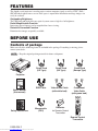
Please read this user's manual thoroughly to ensure correct usage through understanding.
BEDIENUNGSANLEITUNG
Bitte lessen Sie diese Bedienungsanleitung zugunsten der korrekten Bedienung
aufmerksam.
MANUEL D'UTILISATION
Nous vous recommandons de lire attentivement ce manuel pour bien assimiler le
fonctionnement de l'appareil.
MANUALE D'ISTRUZIONI
Vi preghiamo voler leggere attentamente il manuale d'sitruzioni in modo tale da poter
comprendere quanto riportato ai fini di un corretto utilizzo del proiettore.
MANUAL DE USUARIO
Lea cuidadosamente este manual del usuario para poder utilizar corretamente el
producto.
GEBRUIKSAANWIJZNG
Lees voor het qebruik alstublieft deze handleiding aandachtig door, om volledig profijt te
hebben van de uitgebreide mogelijkheden.
BRUKERHÅNDBOK
Vennligst les denne bruksanvisningen grundig for å være garantert driftssikker bruk.
ENGLISH
USER'S MANUAL
ITALIANO FRANÇAIS DEUTSCH
CP-X980W/X985W
NEDERLANDS ESPAÑOL
Liquid Crystal Projector
TECHNICAL
REGULATORY NOTICES
Downloaded from www.Manualslib.com manuals search engine
TECHNICAL PORTGÊS
Para assegurar o uso correto do equipamento, por favor leia atentamente este manual do
usuário.
NORSK
INSTRUÇÕES DO PROPRIETÁRIO
Liquid Crystal Projector
ENGLISH
USER'S MANUAL
Thank you for purchasing this liquid crystal projector.
WARNING • Please read the accompanying manual “SAFETY
INSTRUCTIONS” and this “USER'S MANUAL” thoroughly to ensure correct
usage through understanding. After reading, store this instruction manual in a
safe place for future reference.
NOTE • The information in this manual is subject to change without notice.
• The manufacturer assumes no responsibility for any errors that may appear in this manual
• The reproduction, transmission or use of this document or contents is not permitted without
express written authority.
TRADEMARK ACKNOWLEDGMENT : PS/2, VGA and XGA are registered trademarks of
International Business Machines Corporation. Apple, Mac and ADB are registered trademarks of
Apple Computer, Inc. VESA and SVGA are trademarks of the Video Electronics Standard
Association. Windows is a registered trademark of Microsoft Corporation. Carefully observe the
trademarks and registered trademarks of all companies, even when not mentioned.
CONTENTS
Page
Page
FEATURES .......................................2
BEFORE USE ...................................2
TROUBLESHOOTING ....................20
Contents of Package ..............................2
Part Names.............................................3
Loading the Batteries..............................5
INSTALLATION ................................6
Installation of the Projector and Screen........6
Angle Adjustment ...................................6
Cabling ...................................................7
Power Connection ..................................8
Example of System Setup ......................8
Plug & Play .............................................8
OPERATIONS ...................................9
Power On ...................................................9
Power Off ................................................9
Basic Operation ....................................10
Setup Menu ..........................................12
Input Menu............................................13
Image Menu..........................................14
Options Menu .......................................15
No Signal Menu ....................................16
MAINTENANCE ..............................17
Lamp.....................................................17
Air Filter ................................................19
Other Maintenance ...............................19
OSD Message ......................................20
Indicators Message ..............................21
Symptom ..............................................22
SPECIFICATIONS...........................23
WARRANTY AND AFTER-SERVICE ......24
.......................................................................................
TABLES
Table 1. Installation Reference.................6
Table 2. Cabling .......................................7
Table 3. Basic Operations ......................10
Table 4. Setup Menu ..............................12
Table 5. Input Menu................................13
Table 6. Image Menu..............................14
Table 7. Options Menu ...........................15
Table 8. No Signal Menu ........................16
Table 9. OSD Message ..........................20
Table 10. Indicator Message ..................21
Table 11. Symptom ................................22
Table 12. Specifications .........................23
.......................................................................................
For "TECHNICAL" and "REGULATORY
NOTICE", see the end of this manual.
ENGLISH-1
Downloaded from www.Manualslib.com manuals search engine
FEATURES
This liquid crystal projector is used to project various computer signals as well as NTSC / PAL /
SECAM video signals onto a screen. Little space is required for installation and large images can
easily be realized.
Outstanding Brightness
The UHB lamp and high-efficiency optical system assure a high level of brightness.
Partial Magnification Function
Interesting parts of images can be magnified for closer viewing.
Distortion Correction Function
Distortion-free images are quickly available.
BEFORE USE
Contents of package
Make sure all of the following items are included in the package. If anything is missing, please
contact your dealer.
NOTE • Keep the original packing material for future reshipment.
Power Cord
(US Type)
Power Cord
(UK Type)
Power Cord
(Europe Type)
USER'S MANUAL
Please read this user's manual thoroughly to ensure correct usage through understanding.
BEDIENUNGSANLEITUNG
Bitte lessen Sie diese Bedienungsanleitung zugunsten der korrekten Bedienung
aufmerksam.
MANUEL D'UTILISATION
A
ATION
Nous vous recommandons de lire attentivement ce manuel pour bien assimiler le
fonctionnement de l'appareil.
MANUALE D'ISTRUZIONI
Vi preghiamo voler leggere attentamente il manuale d'sitruzioni in modo tale da poter
comprendere quanto riportato ai fini di un corretto utilizzo del proiettore.
MANUAL DE USUARIO
Lea cuidadosamente este manual del usuario para poder utilizar corretamente el
producto.
GEBRUIKSAANWIJZNG
Lees voor het qebruik alstublieft deze handleiding aandachtig door, om volledig profijt te
hebben van de uitgebreide mogelijkheden.
BRUKERHÅNDBOK
å være garantert driftssikker bruk.
NEDERLANDS ESPAÑOL ITALIANO FRANÇAIS DEUTSCH
ENGLISH
Projector
TECHNICAL
REGULATO
A RY NOTICES
ATO
TECHNICAL PORTGÊS
usuário.
NORSK
INSTRUÇÕES DO PROPRIETÁRIO
User’s Manual
(this manual)
RGB Cable
Video/Audio Cable
(with white lead)
Component
Video Cable
(with green lead)
VIDEO
STANDBY/ON
LASER
RGB
BLANK
AUTO
MENU
POSITION
MENU SELECT
Safety Instructions
Mouse cable
(PS/2)
Batteries
for Remote Control
Transmitter
RESET
PinP
FREEZE
VOLUME
MAGNIFY
OFF
MUTE
FOCUS
ZOOM
Remote Control
Transmitter
ENGLISH-2
Downloaded from www.Manualslib.com manuals search engine
Part Names
ZOOM Button
FOCUS Button
ZOOM
MUTE Button
FOCUS
MUTE
INPUT Button
INPUT
MENU
STANDBY/ON Button
STANDBY/ON
LAMP POWER TEMP
MENU Button
RESET
LAMP Indicator
RESET Button
POWER Indicator
TEMP Indicator
Control Panel
(Refer to P.9 "OPERATIONS")
Control Panel
Ventilation Openings
(exhaust)
Remote Control Sensor
Lens
Carrying Handle
Foot Adjuster
Air Filter and Intake
for the Cooling Fan
Lens Cap
Front/Right View
Foot Adjuster
Remote Control Sensor
Terminal Panel
(Refer below)
Speaker
Power Switch
AC Inlet
(to Power Cord)
Rear/Left View
RGB IN 1 Terminal
RGB IN 2 Terminal
DIGTAL Terminal
DIGTAL
S-VIDEO Terminal
RGB IN
VIDEO Terminal
S-VIDEO
AUDIO(MONO)/L
Terminal
2
CONTROL Terminal
COMPO
NENT
VIDEO
CONTROL
RGB OUT
VIDEO
(MONO)/L
AUDIO
AUDIO R Terminal
USB
R
RGB OUT Terminal
CB/PB
AUDIO IN
RGB 1 RGB 2
DIGITAL
AUDIO
OUT
AUDIO IN RGB1 Terminal
AUDIO IN RGB2 Terminal
AUDIO OUT Terminal
CR/PR
USB Terminal
Terminal
Panel
COMPONENT VIDEO
Y Terminal
CB/PB Terminal
CR/PR Terminal
ENGLISH-3
Downloaded from www.Manualslib.com manuals search engine
ENGLISH
BEFORE USE (continued)
BEFORE USE (continued)
Part Names (continued)
VIDEO Button
STANDBY/ON Button
BLANK Button
EO
VID
STA
/ON
NDBY
L
LASER Button
R
ASE
RGB Button
B
RG
Disk Pad
BLAN
MOUSE / RIGHT Button
K
Used to operate the
mouse shift function and
left click function.
Used to click the right
mouse button.
POSITION Button
AUTO Button
MENU Button
O
AUT
MENU SELECT Button
ME
NU
M
Used to click the left
mouse button.
RESET Button
ITION
POS
ENU
SEL
Used to click the right
mouse button.
ECT
E
RES
T
FREEZE Button
PinP
EZE
FRE
,
,
,
ME
VOLU
Button
Used to operate the
mouse shift function.
PinP Button
NIFY
MAG
OFF
TE
MU
VOLUME Button
MUTE Button
ZOOM Button
US
M
ZOO
FOC
FOCUS Button
MAGNIFY Button
REMOTE CONTROL TRANSMITTER
(Refer to P.9 "OPERATIONS")
These functions works when the mouse control function is activated. Remember, the POSITION,
BLANK ON and MENU ON functions disable the mouse control function.
WARNING • The laser pointer of the remote control transmitter is used in
place of a finger or rod. Never look directly into the laser beam outlet or point
the laser beam at other people. The laser beam can cause vision problems.
CAUTION
LASER RADIATIONDO NOT STARE INTO BEAM
WAVE LENGTH: 650nm
MAX . OUTPUT: 1mW
CLASS 2 LASER PRODUCT
RADIAZIONI LASER
NON GUARDARE NEL RAGGIO LUCE
APPARECCHIO LASER DI CLASSE 2
RAYONNEMENT LASER
MANUFACTURED
NE PAS REGARDER DANS
LE FAISCEAU APPAREIL
A LASER DE CLASSE 2
LASER-STRAHLUNG
PLACE OF
MANUFACTURER:A
NICHT IN DEN STRAHL
MADE IN JAPAN
BLICKEN LASER KLASSE2
IEC60825-1:1993+A1:1997
NOTE To prevent any malfunction;
• Do not give the remote control transmitter any physical impact. Take care not to drop.
• Do not place the heavy objects on the remote control transmitter.
• Do not wet the remote control transmitter or place it on any wet object.
• Do not place the remote control transmitter close to the cooling fan of the projector.
• Do not disassemble the remote control transmitter in case of malfunction. Please bring it to the
service station.
ENGLISH-4
Downloaded from www.Manualslib.com manuals search engine
BEFORE USE (continued)
Install the AA batteries into the remote control
transmitter.
1. Remove the battery cover.
Push the knob while lifting up the battery cover.
2. Load the batteries.
Make sure the plus and minus poles are correctly
oriented.
3. Close the battery cover.
ENGLISH
Loading the Batteries
1
2
CAUTION • Use only the specified batteries with this remote control
transmitter. Also, do not mix new and old batteries. This could cause in
battery cracking or leakage, which could result in fire or personal injury.
• When loading the batteries, make sure the plus and minus terminals are
correctly oriented as indicated in the remote control transmitter. Incorrect
orientation could cause battery cracking or leakage, which could result in
personal injury or pollution of the surrounding environment.
• When you dispose the battery, you obey the law in the relative area or country.
• Keep the battery away from children and pets.
• When not to be used for an extended period, remove the batteries from the
remote control transmitter.
NOTE Replace the batteries when remote control transmitter operation becomes difficult.
ENGLISH-5
Downloaded from www.Manualslib.com manuals search engine
INSTALLATION
Installation of the Projector and Screen
Refer to the drawing and table below for determining of the screen size and projection distance.
The projection distances shown in the table below
Screen
are for full size (1024 x 768 dots).
a: Distance from the projector to the screen. (±10%)
b: Distance from the lens center to the bottom of the
screen. (±10%)
Table 1. Installation Reference
Screen size
[inches (m)]
a [inches (m)]
Min.
Max.
b
[inches (cm)]
40 (1.0)
60 (1.5)
55 (1.4)
85 (2.2)
73 (1.9)
114 (2.9)
1
2
(3)
(4)
80 (2.0)
114 (2.9)
151 (3.8)
2
(6)
100 (2.5)
144 (3.7)
191 (4.9)
3
(7)
120 (3.0)
176 (4.5)
231 (5.9)
3
(9)
150 (3.8)
220 (5.6)
282 (7.2)
4 (11)
200 (5.0)
291 (7.4)
386 (9.8)
6 (15)
Top View
Lens center
b
a
Side View
CAUTION • Install the projector in a suitable environment according to
instructions of the accompanying manual “SAFETY INSTRUCTIONS” and this
manual.
• Please basically use liquid crystal projector at the horizontal position. If you use
liquid crystal projector by the lens up position, the lens down position and the side up
position, this may cause the heat inside to build up and become the cause of damage.
Be especially careful not to install it with ventilation holes blocked.
• Do not install LCD projector in smoke effected environment. Smoke residue may
buildup on critical parts (i.e.LCD panel, Lens Assy etc.).
Angle Adjustment
Use the foot adjusters on the bottom of the
projector to adjust the projection angle. It is
variable within 0˚ to 9˚ approximately.
1. Lift up the front side of the projector, and
pressing the foot adjuster button, adjust the
projection angle.
2. Release the button to lock at the angle to be
fixed.
3. Make the foot adjusters screw for fine
adjustment. Do not force the adjusters to make
screw. This could damage the adjusters or
cause the lock to fail.
Foot Adjusters
Variable within the range of approximately 0° - 9°
CAUTION • Do not release the foot adjuster button unless the projector is
being held; otherwise, the projector could overturn or the fingers could get
caught and cause personal injury.
ENGLISH-6
Downloaded from www.Manualslib.com manuals search engine
INSTALLATION (continued)
ENGLISH
Cabling
Refer to the table below for connecting each terminal of the projector to each device.
Table 2. Cabling
Function
Analog RGB input
Terminal
RGB IN 1
RGB IN 2
Analog RGB output
RGB OUT
Digital RGB input
DIGITAL
Audio input
(from the computer)
AUDIO IN [RGB 1] / [DIGITAL]
(interlocked with RGB IN 1 or
DIGITAL)
Cable
Accessory RGB cable or optional RGB
cable with D-sub 15-pin shrink jack and
inch thread screws
Optional digital RGB cable with inch thread
screws
Optional audio cable with stereo mini jack
AUDIO IN [RGB 2]
(interlocked with RGB IN 2)
PS/2 mouse control
Accessory PS/2 mouse cable
ADB mouse control
Optional ADB mouse cable
CONTROL
Serial mouse control
Optional Serial mouse cable
RS-232C communication
Optional RS-232C cable
USB mouse control
USB
Optional USB cable
S-video input
S-VIDEO
Optional S-video cable with mini DIN 4-pin
jack
Video input
VIDEO
Accessory video/audio cable
COMPONENT VIDEO Y
Component video input
COMPONENT VIDEO CB/PB
Accessory component video cable
COMPONENT VIDEO CR/PR
Audio input
(from video equipment)
AUDIO (MONO)/L
AUDIO R
Accessory video/audio cable or optional
audio cable with RCA jack
Audio output
AUDIO OUT
Optional audio cable with stereo mini jack
CAUTION • Incorrect connecting could result in fire or electrical shock.
Please read this manual and the separate “SAFETY INSTRUCTIONS”.
• Before connecting, turn off to all devices to be connected, except for the USB
cable.
• The cables may have to be used with the core set to the projector side. Use the
cables which are included with the projector or specified.
NOTE • Before connecting, read instruction manuals of the devices to be connected, and make sure that the
projector is compatible with the device.
• Secure the screws on the connectors and tighten.
• For some RGB input modes, the optional Mac adapter is necessary.
• To select the digital RGB input, the comuter may need some settings. See the manuals of the computer for
details.
• Some computers may have multiple display screen modes. Use of some of these modes will not be possible
with this projector.
• Refer to the “TECNICAL” section for the pin assign of connectors and RS-232C communication data.
• When the DIGITAL terminal is used, the RGB OUT terminal may not function.
ENGLISH-7
Downloaded from www.Manualslib.com manuals search engine
INSTALLATION (continued)
Power Connection
Use the correct one of the enclosed power cords depending on the power outlet to be used.
Connect the AC inlet of the projector to the power outlet firmly by the power cord.
CAUTION • Be carful in handling the power
cord according to instructions of the
accompanying manual "SAFETY INSTRUCTIONS"
and this manual.
• Connect the power cord firmly. Avoid using a
loose, unsound outlet or contact failure.
Power outlet
AC Inlet
Power Cord
Example of system setup
Computer
(desktop type)
Computer
(notebook type)
S-Video Tape
Recorder
DIGTAL
RGB IN
S-VIDEO
COMPO
NENT
VIDEO
2
Display
Monitor
CONTROL
RGB OUT
VIDEO
(MONO)/L
AUDIO
USB
R
CB/PB
AUDIO IN
RGB 1 RGB 2
DIGITAL
AUDIO
OUT
CR/PR
Speaker
with
amplifier
DVD Player
Computer (desktop type)
NOTE • When connecting with notebook computer, set to valid the RGB external image output
(setting CRT display or simultaneous display of LCD and CRT). Please read instruction manual of
the notebook for more information.
Plug & Play
This projector is VESA DDC 1/2B compatible. Plug & play is possible by connecting to a computer
that is VESA DDC (Display Data Channel) compatible.
Please use this function by connecting the accessory RGB cable with RGB IN 1 terminal (DDC
1/2B compatible), or by connecting an optional digital RGB cable with DIGITAL terminal (DDC
2B compatible). Plug & play may not operate by other connecting.
NOTE • Plug & play is a system configured with peripheral equipment including a computer and
display, and an operating system.
• This projector is recognized as a plug & play monitor. Use the standard display drivers.
• Plug & play may not operate by the computer to connect. Plug & play will not operate in the
connection with Apple computer.
ENGLISH-8
Downloaded from www.Manualslib.com manuals search engine
POWER Indicator
STANDBY/ON Button
STANDBY/
ON Button
VIDEO
STANDBY/ON
LASER
RGB
BLANK
ZOOM button
FOCUS button
AUTO
MENU
POSITION
MENU SELECT
RESET
PinP
Power Switch
FREEZE
VOLUME
MAGNIFY
OFF
FOCUS button
MUTE
FOCUS
Lens cap
ZOOM
ZOOM button
Power ON
1. Check that the power cord is connected correctly.
2. Set the power switch to [ | ]. The standby mode is selected, and the POWER indicator is turned to
orange.
3. Press the STANDBY/ON button
on the control panel or the remote control transmitter.
Warm-up begins and the POWER indicator blinks in green.
4. The POWER indicator ceases blinking and turns to green when power is on. Remove the lens
cap.
5. Adjust picture size using the ZOOM button.
6. Adjust focus using the FOCUS button .
Power OFF
1. Press the STANDBY/ON button
on the control panel or the remote control transmitter for
approximately two second. The projector lamp is extinguished and lamp cooling begins. The
POWER indicator blinks orange during lamp cooling. Pressing the STANDBY/ON button
has no effect while the POWER indicator is blinking.
2. The system assumes the Standby mode when cooling is complete, and the POWER indicator
ceases blinking and changes to orange. Check that the indicator is orange and set the Power
switch to [O].
3. The POWER indicator is extinguished when power is off. Attach the lens cap.
WARNING • Please read this manual, and the separate “SAFETY
INSTRUCTIONS” thoroughly before using the equipment. Always ensure that
the equipment is used safely.
NOTE • Except in emergencies, do not turn off unless the POWER indicator is orange as it will
reduce the life of the projector lamp.
• To prevent any troble, turn on/off the projector when the computer or video tape recorder is OFF.
Providing a RS-232C cable is connected, turn on the computer before the projector.
ENGLISH-9
Downloaded from www.Manualslib.com manuals search engine
ENGLISH
OPERATIONS
OPERATIONS (continued)
Basic Operation
The basic operations shown in Table 3 is performed from the supplied remote control transmitter or
the projector control panel. Items indicated by (*) may be used from the control panel.
Table 3 . Basic Operation
Item
Description
Select Input Signal (*) : Press the INPUT button.
RGB IN 1 → RGB IN 2 → DIGITAL
→ VIDEO → S-VIDEO → COMPONENT VIDEO (→ RGB IN 1)
Select RGB Input : Press the RGB button.
INPUT
SELECT
VIDEO/S-VIDEO/COMPONENT VIDEO → RGB IN 1/RGB IN 2/DIGITAL
RGB IN 1 → RGB IN 2 → DIGITAL (→ RGB IN 1)
Select Video Input : Press the VIDEO button.
RGB IN 1/RGB IN 2/DIGITAL → VIDEO/S-VIDEO/COMPONENT VIDEO
VIDEO → S-VIDEO → COMPONENT VIDEO (→ VIDEO)
• The selected signal name is displayed for approximately 3 seconds when the input
signal is changed.
Set/Clear Position Adjustment Mode : Press the POSITION button.
The [
] icon is displayed in the POSITION mode.
POSITION
Image Position Adjustment: Press the
POSITION mode.
,
,
and
buttons in the
RESET (*)
Initialise Each Item : Select an item and press the RESET button.
Initialise Position Adjustment : Press the RESET button and the
POSITION mode. This function is valid only when RGB signal is input.
• Valid only in the MAGNIFY mode with a video signal is input.
• After approximately 10 seconds of inactivity the [ ] icon is extinguished and the
POSITION mode is cleared automatically.
•
, ,
and
buttons may operate as the mouse control button. Refer to page 4.
• Valid except for the VOLUME, LANGUAGE and H PHASE.
• The RESET button may operate as the mouse control button. Refer to page 4.
MAGNIFY
Set MAGNIFY Mode : Press the MAGNIFY
button.
Move Magnified Area : Run the POSITION in the MAGNIFY mode.
Adjust Magnification : Press the MAGNIFY
/
button in MAGNIFY
mode.
Clear MAGNIFY Mode : Press the MAGNIFY
button.
OFF
• The MAGNIFY mode is cleared by running or setting the AUTO, ASPECT, INPUT
SELECT or VIDEO, or by changing the input signal.
Set/Clear FREEZE Mode : Press the FREEZE button. The [II] icon is
displayed, and the image frozen, in the FREEZE mode.
FREEZE
• The FREEZE mode is cleared by running or setting POSITION, VOLUME, MUTE,
Automatic Adjustment, BLANK ON/OFF, or MENU ON/OFF, or by changing the input
signal.
• Do not forget to clear frozen static images.
NOTE • Use the remote control transmitter at a distance of approximately 5m from the sensor on
the front of the projector, and within a range of 30° left-right. Strong light and obstacles will
interfere with operation of the remote control transmitter.
ENGLISH-10
Downloaded from www.Manualslib.com manuals search engine
OPERATIONS (continued)
ENGLISH
Items indicated by (*) may be used from the control panel.
Table 3. Basic Operation (continued)
Item
Description
VOLUME
Volume Adjustment : Press the VOLUME
MUTE (*)
Set/Clear Mute Mode : Press the MUTE button. No sound is heard in the
MUTE mode.
AUTO
button.
/
Automatic Adjustment at RGB Input : Press the AUTO button. Horizontal
position(H.POSIT), vertical position (V.POSIT),clock phase (H.PHASE), and
horizontal size(H.SIZE) are automatically adjusted. Use with the window at
maximum size in the application display.
Automatic Adjustment at Video Input : Press the AUTO button. A signal
type appropriate for the input signal is selected automatically. Valid only
when AUTO is set for VIDEO on the menu.
• This operation requires approximately ten seconds. It may not function correctly
with some input signals.
BLANK
ON/OFF
Set/Clear Blank Mode: Press the BLANK button. No image is displayed in
the Blank mode. The screen color is as set in BLANK on the Image menu.
Menu Display Start/Stop: Press the MENU button.
MENU
• The menu display is terminated automatically after approximately ten seconds of
ON/OFF (*)
inactivity.
Select Menu Type: Press the MENU SELECT button. Allows the user to
select the normal menu or the single menu. Only the selected item is
displayed on the single menu, and other items are displayed with the
and
buttons as with the normal menu.
MENU
SELECT
• Valid only when the Setup menu is used. Push the MENU SELECT button after
selecting items such as "BRIGHTNESS".
• The MENU SELECT button may operate as the mouse control button. Refer to
page 4.
Normal menu
Single menu
(MENU SELECT)
SETUP
INPUT
BRIGHT
CONTRAST
V POSIT
H POSIT
H PHASE
H SIZE
COLOR BAL R
COLOR BAL B
ASPECT
IMAGE
OPT.
0
-2
100
100
+1
800
0
0
CONTRAST
P.IN P.
MODE
Select Mode of P.IN P. Display : Press the PinP button.
Small → Large → P.IN P. off ( → Small)
ZOOM
Adjust Screen Size : Press the ZOOM
/
FOCUS
Adjust Focus : Press the FOCUS
button.
-2
• Valid only at RGB IN 1, RGB IN 2 or DIGITAL input.
/
button.
ENGLISH-11
Downloaded from www.Manualslib.com manuals search engine
OPERATIONS (continued)
Setup Menu
SETUP
The following adjustments and settings are possible
when SETUP is selected at the top of the menu. Part
of the Setup menu differs between RGB input and
video input. Select an item with the
and
buttons, and start operation. Use the Single menu to
reduce menu size (see Table 3, MENU SELECT).
Table 4. Setup Menu
Item
INPUT
BRIGHT
CONTRAST
V POSIT
H POSIT
H PHASE
H SIZE
COLOR BAL R
COLOR BAL B
ASPECT
IMAGE
OPT.
SETUP
0
-2
INPUT
IMAGE
OPT.
0
+1
+1
0
0
0
0
BRIGHT
CONTRAST
SHARPNESS
COLOR
TINT
COLOR BAL R
COLOR BAL B
ASPECT
100
100
+1
800
0
0
VIDEO
S-VIDEO
COMPONENT VIDEO
RGB IN 1
RGB IN 2
DIGITAL
RGB IN 1
DIGTAL
RGB IN 2
Description
VIDEO
S-VIDEO
COMPONENT
✔
✔
✔
↔ Strong
✔
✔
✔
↔ Up
✔
-
-
↔ Right
✔
-
-
Adjustment: Left
↔ Right
• Adjust to eliminate flicker.
✔
-
-
↔ Large
• The image may not be displayed correctly if the horizontal
size is excessive. In such cases, press the RESET button,
and initialize the horizontal size.
✔
-
-
↔ Clear
-
-
✔
↔ Dark
-
-
✔
-
-
✔
BRIGHT
Adjustment: Dark
CONTRAST
Adjustment: Weak
V POSIT
Adjustment: Down
H POSIT
Adjustment: Left
H PHASE
↔ Light
Adjustment: Small
H SIZE
SHARPNESS Adjustment: Soft
COLOR
TINT
Adjustment: Light
↔ Green
• Valid only when NTSC or NTSC 4.43 signal is received.
Adjustment: Red
COLOR BAL R Adjustment: Light
↔ Dark
✔
✔
✔
COLOR BAL B Adjustment: Light
↔ Dark
✔
✔
✔
✔
✔
-
-
-
✔
Select Image Aspect Ratio : 4:3[
]
↔
16:9[
]
Select Position of Image:
Press the
button while 16:9[
] is selected.
Center →
Down →
Up ( → Center
)
ASPECT
Select Image Aspect Ratio:
4:3[
]
↔
16:9[
]
↔
4:3 small[
Select Position of Image :
Press the
button while 16:9[
] / 4:3 small[
is selected.
Center →
Down →
Up ( → Center
)
]
]
• 4:3 small may not be displayed correctly with some input
signals.
ENGLISH-12
Downloaded from www.Manualslib.com manuals search engine
Input Menu
The following functions are available when INPUT is selected on the
menu. Select an item with the
and
buttons, and start or stop
operation with the
and
buttons. The function indicated (**) are
effective on video input mode only, not on RGB input mode, except in
the P.IN P. window on RGB input mode.
SETUP
INPUT
AUTO
RGB
VIDEO
VIDEO NR
Progressive
BLACK
IMAGE
OPT.
EXECUTE
CANCEL
Table 5. Input Menu
Item
AUTO
Description
Automatic Adjustment at RGB Input: Select the EXECUTE with the
button. Horizontal position (H.POSIT), vertical position (V.POSIT), clock
phase (H.PHASE), and horizontal size (H.SIZE) are automatically adjusted.
Use with the window at maximum size in the application display.
Automatic Adjustment at Video Input: Select the EXECUTE with the
button. A signal type appropriate for the input signal is selected
automatically when EXECUTE is selected automatically. Valid only when
AUTO is set for VIDEO on the menu.
• This operation requires approximately 10 seconds. It may not function correctly with
some input signals. Pressing the AUTO button in this case may correct this problem.
• This function is the same as for the AUTO function in Basic operation.
RGB
Displays RGB Input Frequency: Displays the horizontal and vertical sync
signal frequencies for RGB input.
• Valid only at RGB input.
Select Video Signal Type: Select the signal type with the
and
buttons. Select NTSC, PAL, SECAM, NTSC4.43, M-PAL, or N-PAL as
appropriate for the input signal. The selection of AUTO enables and
executes the function AUTO (Automatic Adjustment at Video Input), except
for the N-PAL input.
VIDEO (**)
VIDEO NR
(**)
Progressive
(**)
• Use this function when the image becomes unstable (eg. the image becomes
irregular, or lacks color) at VIDEO/S-VIDEO input.
• Automatic Adjustment requires approximately ten seconds. It may not function
correctly with some input signals. Pressing the AUTO button in this case may correct
this problem except for the N-PAL input.
• For the COMPONENT VIDEO input, this function is not effective and the signal type
is distinguished automatically. Refer to the item HDTV of the OPT. Menu for the
signal of HDTV.
Set/Clear Noise Reduction Mode: Select the TURN ON / TURN OFF with
the /
button. When the TURN ON is selected, the NR mode is active
and the noise on screen of the video input will be reduced.
Select Progressive Mode: Select the mode suitable for the input signal
with the
and
buttons. The TV mode and the CINEMA mode convert
the interlaced video signal into the progressive signal. The CINEMA mode is
adptable 2-3 Pull-Down system to the conversion.
• Use this function to raise resolution, at the interlaced video input except HDTV
signal.
BLACK(**)
Set/Clear Black Enhancement Mode: Select the TURN ON / TURN OFF
with the / button. When the TURN ON is selected, the black
enhancement mode is active and the contrast ratio of the screen for the
video input will be raised by making black level darker.
ENGLISH-13
Downloaded from www.Manualslib.com manuals search engine
ENGLISH
OPERATIONS (continued)
OPERATIONS (continued)
Image Menu
SETUP
The following adjustments and settings are available when IMAGE is
selected on the menu. Select an item with the
and
buttons, and
start operation.
INPUT
IMAGE
OPT.
+1
KEYSTONE
BLANK
MIRROR
START UP
P. IN P.
Table 6. Image Menu
Item
Description
Keystone Adjustment:
KEYSTONE Reduce size of bottom of image
↔ Reduce size of top of image
• When this function is activated, the image may not be displayed correctly with
some input signals.
Select Blank Screen Color: Select color with the
BLANK
and
buttons.
• The image is cleared when the BLANK mode is set with BLANK ON, or when there
is no signal, and the entire screen is displayed in the selected color.
Operation Start/Stop: Press the
or
button.
Select Mirror Status: Select mirror status with
and
MIRROR
buttons.
Operation Start/Stop: Press the
or
button.
Setup Initial Screen Display: Select TURN ON with the
Clear Initial Screen Display: Select TURN OFF with the
START UP
button.
button.
• Note that if TURN OFF is selected the blank screen is displayed in blue when there
is no signal.
P. IN P.
Operation Start/Stop: Press the
or
button.
Select Position of P. in P. Display : Press the
or
↔
↔
↔
(
↔
• Valid only at RGB IN 1, RGB IN 2 or DIGITAL input.
ENGLISH-14
Downloaded from www.Manualslib.com manuals search engine
)
button.
Options Menu
SETUP
The following adjustments and settings are available when OPT. is
selected on the menu. Select an item with the
and
buttons, and
start operation. The function indicated (**) are effective on video input
mode only, not on RGB input mode, except in the P.IN P. window on
RGB input mode.
INPUT
IMAGE
OPT.
16
VOLUME
MENU COLOR
LANGUAGE
AUTO OFF
SYNC ON G
HDTV
Table 7. Options Menu
Item
Description
↔ Increase VOLUME
VOLUME
Volume Adjustment: Reduce VOLUME
MENU COLOR
Select Menu Background Color: Select with the
and
buttons.
LANGUAGE
Operation Start/Stop: Press the
or
button.
Select Menu Display Language: Select with the
and
buttons.
AUTO OFF
Operation Start/Stop: Press the
or
button.
Set AUTO OFF: Set 1~99 minutes with the
and
buttons. The
system automatically enters the standby mode when a signal is not
received for the set time.
Clear AUTO OFF: Select STOP (0 min.) with the
button. When
STOP is selected the system does not enter the standby mode even if
no signal is received.
SYNC ON G
HDTV (**)
Operation Start/Stop: Press the
or
button.
SYNC ON G Valid: Select TURN ON with the
button.
SYNC ON G Invalid: Select TURN OFF with the
button.
• May not be displayed correctly with some input signals when SYNC ON G is
valid. In such cases, remove the signal connector so that no signal is received,
set SYNC ON G to invalid, and reconnect the signal.
Select HDTV mode: Select the 1035i mode or 1080i mode suitable for
the input signal with the
/
button.
ENGLISH-15
Downloaded from www.Manualslib.com manuals search engine
ENGLISH
OPERATIONS (continued)
OPERATIONS (continued)
No Signal Menu
The same adjustments and settings are available as with the Image and
Options menus when the MENU button is pressed during display of the
“NO INPUT IS DETECTED ON ***” or “SYNC IS OUT OF RANGE
ON ***” message while no signal is received.
VOLUME
KEYSTONE
BLANK
MIRROR
START UP
MENU COLOR
LANGUAGE
AUTO OFF
SYNC ON G
16
+1
Table 8. No Signal Menu
Item
Description
VOLUME
↔ Increase VOLUME
• When this function is used, audio input is automatically switched to video. The
audio input can be switched by moving the DISK PAD left and right during the
display of the volume adjustment bar. The volume adjustment bar is displayed by
pressing VOLUME
or VOLUME
button.
KEYSTONE
Keystone Adjustment: Reduce the size of bottom of image
Reduce the size of top of image
Volume Adjustment: Reduce VOLUME
BLANK
MIRROR
START UP
Select Blank Screen Color: Select the color with the
buttons.
↔
and
• When the blank mode is set with BLANK ON, by absence of a signal, or by
input of a non-standard signal, the image is cleared and the complete screen is
displayed in the selected color.
Operation Start/Stop: Press the
or
button.
Select Mirror Status: Select the mirror status with the
buttons.
and
Operation Start/Stop: Press the
or
button.
Setup Initial Screen Display: Select the TURN ON with the
Clear Initial Screen Display: Select the TURN OFF with the
button.
button.
• Note that if TURN OFF is selected the blank screen is displayed in blue when
there is no signal.
MENU COLOR
Select Menu Background Color: Select the color with the
buttons.
LANGUAGE
Operation Start/Stop: Press the
or
button.
Select Menu Display Language: Select the language with the
buttons.
AUTO OFF
Operation start/stop: Press the
or
button.
Set AUTO OFF: Set 1~99 minutes with the
and
buttons. The
system automatically enters the standby mode when a signal is not
received for the set time.
Clear AUTO OFF: Select the STOP (0 min.) with the
button. When
the STOP is selected the system does not enter the standby mode even
if no signal is received.
SYNC ON G
and
and
Operation Start/Stop: Press the
or
button.
SYNC ON G Valid: Select the TURN ON with the
button.
SYNC ON G Invalid: Select the TURN OFF with the
button.
• May not be displayed correctly with some input signals when the SYNC ON G
is valid. In such cases, remove the signal connector so that no signal is received,
set the SYNC ON G to invalid, and reconnect the signal.
ENGLISH-16
Downloaded from www.Manualslib.com manuals search engine
Lamp
HIGH VOLTAGE
HIGH TEMPERATURE
HIGH PRESSURE
Contact your dealer before replacing the lamp.
For the optional lamp, see the item “Option Parts” of the Table 12.
Before replacing the lamp, switch power OFF, remove the power cord from the power outlet, and
wait approximately 45 minutes until the lamp has cooled. The lamp may explode if handled at high
temperatures.
WARNING • For disposal of used lamp, treat
according to the instruction of community
authorities.
• Since the lamp is made of glass, do not apply shock
to it and do not scratch it.
• Also, do not use old lamp. This could also cause
explosion of the lamp.
• If it is probable that the lamp has exploded (explosive
sound is heard), disconnect the power plug from the
power outlet and ask your dealer to replace lamp. The
lamp is covered by front glass , but, in rare cases, the
reflector and the inside of the projector may be
damaged by scattered broken pieces of glass, and
broken pieces could cause injury when being handled.
• Do not use the projector with the lamp cover removed.
Lamp
Reflector
Front
glasss
Lamp Life
Projector lamps have a finite life. The image will become darker, and hues will become weaker,
after a lamp has been used for a long period of time.
Replace the lamp if the LAMP indicator is red, or the CHANGE THE LAMP message appears
when the projector is switched ON. See Table 9 of P.20 and Table 10 of P.21.
NOTE • The LAMP indicator is also red when the lamp unit reaches high temperature. Before
replacing the lamp, switch power OFF, wait approximately 20 minutes, and switch power ON again.
If the LAMP indicator is still red, replace the lamp.
ENGLISH-17
Downloaded from www.Manualslib.com manuals search engine
ENGLISH
MAINTENANCE
MAINTENANCE (continued)
Replacing the Lamp
1. Switch the projector OFF, remove the power cord from the
power outlet, and wait at least 45 minutes for the unit to cool.
2. Prepare a new lamp.
3. Check that the projector has cooled sufficiently, and gently
turn it upside down.
4. Loosen the screw as shown in the diagram, and remove the
lamp cover.
5. Loosen the two screws, and gently remove the lamp while
holding the grips. Touching the inside of the lamp case may
result in uneven coloring.
6. Install the new lamp and tighten the two screws firmly. Also
steadily push the opposite side of the screwed lamp into the
unit.
7. Replace the lamp cover in position and tighten the screw
firmly.
8. Gently turn the projector right-side up.
CAUTION • Ensure that screws are tightened
properly. Screws not tightened fully may result
in injury or accidents.
• Do not use the projector with the lamp cover
removed.
Resetting the Lamp Timer
Reset the lamp timer after replacing the lamp. When the lamp has been replaced after the LAMP
indicator is red, or the CHANGE THE LAMP message is displayed, complete the following
operation within ten minutes of switching power ON. The power will be turned off automatically in
over 10 minutes.
1. Switch power ON, and press the RESET button, for approximately three seconds. The ‘LAMP
xxxx hr’ message will appear on the lamp timer on the bottom of the screen.
2. Press the MENU button on the remote control transmitter, or the RESET button on the control
panel, while the lamp timer is displayed. The ‘LAMP xxxx → 0 ■ CANCEL’ message will
then appear.
3. Press the
and select 0, and wait until the timer display is cleared.
NOTE • Do not reset the lamp timer without replacing the lamp. Reset the lamp timer always
when replacing the lamp. The message functions will not operate properly if the lamp timer is not
reset correctly.
ENGLISH-18
Downloaded from www.Manualslib.com manuals search engine
Air Filter Maintenance
The air filter should be cleaned as described below at intervals of approximately 100 hours.
1. Switch the projector power supply OFF, and remove the power cord from the power outlet.
2. Clean the air filter with a vacuum cleaner.
CAUTION • Switch power OFF and remove the power cord from the power
outlet before beginning maintenance work. Please read the separate “SAFETY
INSTRUCTIONS” thoroughly to ensure that maintenance is performed correctly.
• Replace the air filter if contamination cannot be removed, or if it is damaged.
Contact your dealer in such case. For the optional air filter, see the item “Option
Parts” of the Table 12.
• Do not use the equipment with the air filter removed.
• When the air filter is clogged with dust etc. the power supply is switched OFF
automatically to prevent the temperature rising inside the projector.
Other Maintenance
Maintenance Inside the Equipment
For safety reasons, ensure that the equipment is cleaned and checked by the dealer once every two
years. Maintaining the equipment by yourself is dangerous.
Cleaning the Lens
Gently wipe the lens with lens cleaning paper. Do not touch the lens with your hands.
Cleaning the Cabinet and Remote control transmitter
Gently wipe with a soft cloth. If dirt and stains etc. are not easily removed, use a soft cloth
dampened with water, or water and a neutral detergent, and wipe dry with a soft, dry cloth.
CAUTION • Switch power OFF and remove the power cord from the power
outlet before beginning maintenance work. Please read the separate “SAFETY
INSTRUCTIONS” thoroughly to ensure that maintenance is performed correctly.
• Do not use detergents or chemicals other than those noted above (e.g. benzene
or thinners).
• Do not use cleaning sprays.
• Do not rub with hard materials, or tap the equipment.
ENGLISH-19
Downloaded from www.Manualslib.com manuals search engine
ENGLISH
MAINTENANCE (continued)
TROUBLESHOOTING
OSD Message
The messages as described below may appear on the screen at power ON. Take the appropriate
measures when such a message appears.
Table 9. OSD Messages
Message
Contents
The message shown at left appears after the lamp has
been used for more than 1300 hours.
CHANGE THE LAMP
The lamp is approaching the end of its life.
AFTER REPLACING LAMP,
Power is switched OFF automatically when the lamp
RESET THE LAMP TIME.
*1) reaches the end of its life. Prepare a new lamp for
installation.
Always reset the lamp timer after replacing the lamp.
CHANGE THE LAMP
AFTER REPLACING LAMP,
RESET THE LAMP TIME.
THE POWER WILL TURN OFF
AFTER ** hr.
*1)
CHANGE THE LAMP
AFTER REPLACING LAMP,
RESET THE LAMP TIME.
THE POWER WILL
TURN OFF
AFTER 0 hr.
The lamp will reach the end of its life in ** hours.
Power will be switched OFF automatically in ** hours.
Replace the lamp as shown in P.17~18 “Lamp”.
Always reset the lamp timer after replacing the lamp.
The lamp has reached the end of its life. Power will be
switched OFF in a few minutes.
Switch power OFF immediately and replace the lamp as
shown in P.17~18 “Lamp”.
Always reset the lamp timer after replacing the lamp.
NO INPUT IS DETECTED
ON ***
No input signal found.
Check signal input connections and signal sources.
SYNC IS OUT OF RANGE
ON ***
The horizontal or vertical frequency of the input signal is
not within the specified range.
Check the specifications of the equipment and the signal
source.
NOTE *1) This message is cleared automatically after approximately three minutes, and appears
every time power is switched ON.
ENGLISH-20
Downloaded from www.Manualslib.com manuals search engine
Indicators Message
The POWER indicator, LAMP indicator, and TEMP indicator are lit and blank as follows. Take the
appropriate measures.
Table 10. Indicators Message
POWER
LAMP
TEMP
indicator indicator indicator
Contents
Lights
orange
Turns off Turns off The Standby mode has been set.
Blinks
green
Turns off Turns off Warming up. Please wait.
Lights
green
Turns off Turns off ON. Normal operation possible.
Blinks
orange
Turns off Turns off Cooling. Please wait.
Lights red
Lights red
Lights
red
Lamp is not lit.
The interior of the equipment may be too hot. Switch
power OFF, wait 20 minutes until the equipment cools,
Turns off and check whether the ventilation openings are blocked,
whether the air filter is dirty, or whether the ambient
temperature exceeds 35 °C. And switch power ON
again. Replace the lamp if the same problem occurs.
Blinks
red
Lamp or lamp cover is not found, or hasn’t been fitted in
correctly.
Switch power OFF, and wait for 45 minutes until the
Turns off
equipment cools. Check fitting of the lamp and lamp
cover, and switch power ON again. Contact your dealer if
the same problem occurs again.
Lights red Turns off
Blinks
red
The cooling fan is not operating.
Switch power OFF, and wait for 20 minutes until the
equipment cools. Check for foreign matters in the fan,
and switch power ON again. Contact your dealer if the
same problem occurs again.
NOTE *1) When the internal temperature becomes excessive power is switched OFF
automatically for safety reasons, and the indicator is extinguished. Set the power switch to [O] and
wait for 20 minutes until the equipment has cooled sufficiently.
ENGLISH-21
Downloaded from www.Manualslib.com manuals search engine
ENGLISH
TROUBLESHOOTING (continued)
TROUBLESHOOTING (continued)
Symptom
Before requesting repair, check in accordance with the following chart. If the situation cannot be
corrected, then contact your dealer.
Table 11. Symptom
Symptom
The power is not
turned on.
Possible cause
Remedy
The main power switch is not
turned on.
Turn on the main power switch.
The power cord is
disconnected.
Plug the power cord into an AC
power outlet.
The input is not correctly set.
Use the projector or remote control
transmitter to set.
10
No signal input.
Connect correctly.
7,8
The projector is not correctly
connected.
Connect correctly.
7,8
No video or audio.
Video is present but
The volume is set to minimum.
no audio.
Press VOLUME
on the remote
control or display the menu screen
and adjust the volume.
Mute is turned on.
Press the MUTE
The projector is not correctly
connected.
Connect correctly.
button.
Audio is present but The brightness adjustment knob Select BRIGHT with the MENU
button and the press the
button.
is rotated fully clockwise.
no video.
The lens cap is still attached.
Colors are pale and Color density and color
color matching is
matching are not correctly
poor.
adjusted.
Images are dark.
Video is blurred.
Page
Remove the lens cap.
8,9
11,15
11
7,8
12
9
Adjust the video.
12
Brightness and contrast are not
correctly adjusted.
Adjust the video.
12
The lamp is nearing the end of
its service life.
Replace with a new lamp.
17
Focus or H PHASE is out of
adjustment.
Adjust the focus or H PHASE.
ENGLISH-22
Downloaded from www.Manualslib.com manuals search engine
9,12
ENGLISH
SPECIFICATIONS
Table 12. Specifications
Item
Specification
Product name
Liquid
crystal
panel
Liquid crystal projector
Panel size
3.3 cm (1.3 type)
Drive system
TFT active matrix
Pixels
786,432 pixels (1024 horizontal x 768 vertical)
Lens
Zoom lens F=1.7 ~ 2.3 f=49.0 ~ 64.0 mm
Lamp
250 W UHB
Speaker
1.2 W + 1.2W (Stereo)
Power supply
AC100 ~ 120V, 4.5A / AC220 ~ 240V, 2.2A
Power consumption
400W
Temperature range
0 ~ 35°C (Operating)
Size
289 (W) x 124 (H) x 350 (D) mm
Weight (mass)
6.4 kg
1
RGB IN
RGB
signal
input
2
Video
signal
input
TMDS, DC: 150~1200 mV / AC: 1.56 Vp-p
TTL Level (Positive/Negative)
DIGITAL
AUDIO IN
Video: Analog 0.7Vp-p, 75Ω terminator (positive)
H/V. sync.: TTL level (positive/negative)
Composite sync.: TTL level
D-sub 15-pin shrink jack
RGB1
200mVrms, 50 kΩ (max. 3.0Vp-p)
DIGITAL
Stereo mini jack
RGB2
VIDEO
1.0Vp-p, 75Ω terminator
RCA jack
S-VIDEO
Brightness signal: 1.0Vp-p, 75Ω terminator
Color signal: 0.286Vp-p (burst signal), 75Ω terminator
Mini DIN 4-pin jack
Y
1.0 Vp-p, 75 Ω Terminator (Positive)
COMPONENT
CB/CR 0.7 Vp-p, 75 Ω Terminator (Positive)
VIDEO
PB/PR 1.0 Vp-p, 75 Ω Terminator (Positive)
AUDIO
Signal
output
Control
functions
L
R
200mVrms, 50 kΩ (max. 3.0Vp-p)
RCA jack
RGB OUT
Video: Analog 0.7Vp-p, 75Ω output impedance (positive)
H/V. sync.: TTL level (positive/negative)
Composite sync.: TTL level
D-sub 15-pin shrink jack
AUDIO OUT
200mVrms, output impedance 1 kΩ (max. 3.0Vp-p)
Stereo mini jack
CONTROL
D-sub 15-pin shrink plug
USB
USB jack (B type)
Optional Parts
Lamp: DT00341
Air Filter: MU0832
* For others, consult your dealer.
NOTE • This specifications are subject to change without notice.
ENGLISH-23
Downloaded from www.Manualslib.com manuals search engine
WARRANTY AND AFTER-SERVICE
If a problem occurs with the equipment, first refer to the P.20 “TROUBLESHOOTING” section and
run through the suggested checks. If this does not resolve the problem contact your dealer or service
company. If repairs are possible, and desirable, they will be charged.
ENGLISH-24
Downloaded from www.Manualslib.com manuals search engine
TECHNICAL
350
Dimension Diagram
124
68
289
Unit : mm
31
Signal Connector Pin Assignment
1. D-sub 15-pin Shrink Connector (RGB IN 1/RGB IN 2/RGB OUT)
Pin No
1
2
3
4
5
6
7
8
Signal
Video input Red
Video input Green
Video input Blue
Ground
Ground Red
Ground Green
Ground Blue
Pin No
Signal
9
10
11
-
12
13
14
Ground
Pin No
15
RGB IN 1: SDA(DDC)
RGB IN 2: RGB OUT: H. sync./ Composite sync.
Vertical sync
Signal
RGB IN 1: SCL(DDC)
RGB IN 2: RGB OUT: -
5 4 3 2 1
10 9 8 7 6
15 14 13 12 11
2. Digital Receptacle Connector (DIGITAL)
Pin No
1
2
3
4
5
6
7
8
9
10
Signal
T.M.D.S. Data 2 T.M.D.S. Data 2 +
T.M.D.S. Data 2 / 4 Shield
DDC Clock
DDC Data
Analog V. Sync.
T.M.D.S. Data 1 T.M.D.S. Data 1 +
Pin No
Signal
11
12
13
14
15
16
17
18
19
20
T.M.D.S. Data 1 / 3 Shield
+5V Power
Ground (+5V, Analog H/V Sync.)
Hot-Plug Sense
T.M.D.S. Data 0 T.M.D.S. Data 0 +
T.M.D.S. Data 0 / 5 Shield
-
Pin No
21
22
23
24
Signal
T.M.D.S. Clock Shield
T.M.D.S. Clock +
T.M.D.S. Clock -
1 2 3 4
5 6 7 8
9 10 11 12 13 14 15 16
17 18 19 20 21 22 23 24
3. Mini Din 4-pin Connector (S-VIDEO)
Signal
1
Color:0.286Vp-p (NTSC, burst signal),75Ω terminator
0.3Vp-p (PAL/SECAM, burst signal),75Ω terminator
2
Brightness:1.0Vp-p, 75Ω terminator
3
Ground
4
Ground
TECHNICAL
Pin No
TECHNICAL - 1
Downloaded from www.Manualslib.com manuals search engine
TECHNICAL
Example of computer signal
Resolution
H×V
fH (kHz)
fV (Hz)
Rating
Signal mode
Display
mode
720 × 400
37.9
85.0
VESA
TEXT
Zoom in
640 × 480
31.5
59.9
VESA
VGA (60Hz)
Zoom in
640 × 480
35.0
66.7
Mac13"mode
Zoom in
640 × 480
37.9
72.8
VESA
VGA (72Hz)
Zoom in
640 × 480
37.5
75.0
VESA
VGA (75Hz)
Zoom in
640 × 480
43.3
85.0
VESA
VGA (85Hz)
Zoom in
800 × 600
35.2
56.3
VESA
SVGA (56Hz)
Zoom in
800 × 600
37.9
60.3
VESA
SVGA (60Hz)
Zoom in
800 × 600
48.1
72.2
VESA
SVGA (72Hz)
Zoom in
800 × 600
46.9
75.0
VESA
SVGA (75Hz)
Zoom in
800 × 600
53.7
85.1
VESA
SVGA (85Hz)
Zoom in
832 × 624
49.7
74.5
Mac16"mode
Zoom in
1024 × 768
48.4
60.0
VESA
XGA (60Hz)
1024 × 768
56.5
70.1
VESA
XGA (70Hz)
1024 × 768
60.0
75.0
VESA
XGA (75Hz)
1024 × 768
68.7
85.0
VESA
XGA (85Hz)
1152 × 864
67.5
75.0
VESA
SXGA (75Hz)
Zoom out
1280 × 960
60.0
60.0
VESA
SXGA (60Hz)
Zoom out
1280 × 1024
64.0
60.0
VESA
SXGA (60Hz)
Zoom out
1280 × 1024
80.0
75.0
VESA
SXGA (75Hz)
Zoom out
NOTE • Some computers may have multiple display screen modes. Use of some of these modes
will not be possible with this projector.
• Be sure to check jack type, signal level, timing and resolution before connecting this projector to a
computer.
• Depending on the input signal, full-size display may not be possible in some cases. Refer to the
number of display pixels above.
• The image might be something wrong with computer by computer on the digital RGB mode. In the
case, it is recommended to reduce the resolution and / or reflesh rate.
TECHNICAL - 2
Downloaded from www.Manualslib.com manuals search engine
TECHNICAL (continued)
Initial set signals
The following signals are used for the initial settings.
The signal timing of some computer models may be different. In such case, refer to adjust the
V.POSIT and H.POSIT of the menu.
Back porch b
Front porch d
Display interval c
Back porch b
Front porch d
Display interval c
DATA
DATA
HSYNC
VSYNC
Sync a
Computer /
Signal
Sync a
Horizontal signal timing (µs)
TEXT
a
2.0
b
3.0
c
20.3
d
1.0
VGA (60Hz)
3.8
1.9
25.4
Mac 13"mode
2.1
3.2
VGA (72Hz)
1.3
VGA (75Hz)
Computer /
Signal
Vertical signal timimg (lines)
a
3
b
42
c
400
d
1
0.6
VGA (60Hz)
2
33
480
10
21.2
2.1
Mac 13"mode
3
39
480
3
3.8
20.3
1.0
VGA (72Hz)
3
28
480
9
2.0
3.8
20.3
0.5
VGA (75Hz)
3
16
480
1
VGA (85Hz)
1.6
2.2
17.8
1.6
VGA (85Hz)
3
25
480
1
SVGA (56Hz)
2.0
3.6
22.2
0.7
SVGA (56Hz)
2
22
600
1
SVGA (60Hz)
3.2
2.2
20.0
1.0
SVGA (60Hz)
4
23
600
1
SVGA (72Hz)
2.4
1.3
16.0
1.1
SVGA (72Hz)
6
23
600
37
SVGA (75Hz)
1.6
3.2
16.2
0.3
SVGA (75Hz)
3
21
600
1
SVGA (85Hz)
1.1
2.7
14.2
0.6
SVGA (85Hz)
3
27
600
1
Mac 16"mode
1.1
3.9
14.5
0.6
Mac 16"mode
3
39
624
1
XGA (60Hz)
2.1
2.5
15.8
0.4
XGA (60Hz)
6
29
768
3
XGA (70Hz)
1.8
1.9
13.7
0.3
XGA (70Hz)
6
29
768
3
XGA (75Hz)
1.2
2.2
13.0
0.2
XGA (75Hz)
3
28
768
1
XGA (85Hz)
1.0
2.2
10.8
0.5
XGA (85Hz)
3
36
768
1
1152×864 (75Hz)
1.2
2.4
10.7
0.6
1152×864 (75Hz)
3
32
864
1
1280×960 (60Hz)
1.0
2.9
11.9
0.9
1280×960 (60Hz)
3
36
960
1
1280×1024 (60Hz)
1.0
2.3
11.9
0.4
1280×1024 (60Hz)
3
38
1024
1
1280×1024 (75Hz)
1.1
1.8
9.5
0.1
1280×1024 (75Hz)
3
38
1024
1
TECHNICAL
TEXT
TECHNICAL - 3
Downloaded from www.Manualslib.com manuals search engine
TECHNICAL (continued)
Connection to the Mouse Control
1. PS/2, ADB or Serial Mouse
(1) Turn off the projector and computer, and connect the two units with the appropriate cable. For
PS/2 mouse control (for IBM and compatible), use the enclosed mouse cable. For others, consult
your dealer.
(2) Disconnect the USB cable from the projector if it is connected. Then turn on the projector.
(3) Turn on the computer.
(4) Start the mouse function. If the mouse has not been started, reboot the computer (soft reboot or
reboot buttons). Refer to the descriptions of “DISC PAD” and “MOUSE/RIGHT button” of page 4.
2. USB Mouse
(1) Connect the projector and computer with a suitable commercially available USB cable. Consult
your dealer to get the cable, if you need.
(2) Start the mouse function. Refer to the descriptions of “DISC PAD” and “MOUSE/RIGHT
button” of page 4.
NOTE • Before connecting, read the instruction manuals of the devices to be connected.
• In the case of notebook type computers with an internal pointing device, the mouse control
function will not work unless the internal pointing device is disabled. In such case, disable the
internal pointing device and change the BIOS setting to select an external mouse before the
operations described in (1) to (5) above.
Also, some computers may not have a utility program to operate a mouse.
Refer to the computer hardware manual for detail.
PS/2 Mouse
Projector
CONTROL Terminal
CLK
DATA
D-sub 15-pin shrink jack
6
2 3 4 5
7 8 9 10
11 12 13 14 15
1
SEL0
RTS
+5V
GND
TECHNICAL - 4
Downloaded from www.Manualslib.com manuals search engine
1
2
3
4
5
6
7
8
9
10
11
12
13
14
15
Computer
1
2
3
4
5
6
DATA
GND
+5V
CLK
Mouse jack
Mini DIN 6-pin
6
5
3
4
2
1
TECHNICAL (continued)
ADB Mouse
Projector
CONTROL Terminal
DATA
D-sub 15-pin shrink jack
6
2 3 4 5
7 8 9 10
11 12 13 14 15
1
RTS
+5V
GND
1
2
3
4
5
6
7
8
9
10
11
12
13
14
15
Computer
1 ADB
2 (POWER ON)
3 +5V
4 GND
Mouse jack
Mini DIN 4-pin
3
4
1
2
Serial Mouse
Projector
CONTROL Terminal
D-sub 15-pin shrink jack
SEL0
RTS
2 3 4 5
6 7 8 9 10
11 12 13 14 15
1
GND
TD
1
2
3
4
5
6
7
8
9
10
11
12
13
14
15
1
2
3
4
5
6
7
8
9
Computer
CD
RD
TD
DTR
GND
DSR
RTS
CTS
RI
Mouse jack
D-sub 9-pin
1
2
6
3
7
5
4
8
9
USB Mouse
2
3
1
4
Computer
Projector
+5V 1
1
+5V
—DATA 2
2 —DATA
+DATA 3
3
GND 4
USB jack
(A type)
+DATA
4 GND
1
2
3
4
USB cable
TECHNICAL - 5
Downloaded from www.Manualslib.com manuals search engine
TECHNICAL
USB jack
(B type)
TECHNICAL (continued)
RS-232C communication
(1) Turn off the projector and computer power supplies and connect with the RS-232C cable.
(2) Turn on the computer power supply and, after the computer has started up, turn on the projector
power supply.
Projector
Control jack
D-sub 15-pin shrink jack
5 4 3 2 1
10 9 8 7 6
15 14 13 12 11
Computer
1
2
3
4
5
SELO 6
RTS 7
8
9
GND 10
11
12
RD 13
TD 14
15
1
2
3
4
5
6
7
8
9
CD
RD
TD
DTR
GND
DSR
RTS
DTS
RI
RS-232C jack
D-sub 9-pin
2
1
6
3
7
Communications setting
19200bps, 8N1
1 Protocol
Consist of header (7 bytes) + command data (6 bytes).
2 Header
BE + EF + 03 + 06 + 00 + CRC_low + CRC_high
CRC_low : Lower byte of CRC flag for command data.
CRC_high : Upper byte of CRC flag for command data.
3 Command data
Command data chart
byte_0
byte_1
byte_2
Action
low
byte_3
Type
high
low
byte_4
byte_5
Setting code
high
low
high
Action (byte_0 - 1)
Action
Classification
Content
1
SET
Change setting to desired value.
2
GET
Read projector internal setup value.
4
INCREMENT
Increment setup value by 1.
5
DECREMENT
Decrement setup value by 1.
6
EXECUTE
Run a command.
TECHNICAL - 6
Downloaded from www.Manualslib.com manuals search engine
4
8
5
9
TECHNICAL (continued)
Requesting projector status (Get command)
(1) Send the request code Header + Command data (‘02H’+‘00H’+ type (2 bytes) +‘00H’+‘00H’)
from the computer to the projector.
(2) The projector returns the response code ‘1DH’+ data (2 bytes) to the computer.
Changing the projector settings (Set command)
(1) Send the setting code Header + Command data (‘01H’+‘00H’+ type (2 bytes) + setting code (2
bytes)) from the computer to the projector.
(2) The projector changes the setting based on the above setting code.
(3) The projector returns the response code ‘06H’ to the computer.
Using the projector default settings (Reset Command)
(1) The computer sends the default setting code Header + Command data (‘06H’+‘00H’+ type (2
bytes) +‘00H’+‘00H’) to the projector.
(2) The projector changes the specified setting to the default value.
(3) The projector returns the response code ‘06H’ to the computer.
Increasing the projector setting value (Increment command)
(1) The computer sends the increment code Header + Command data (‘04H’+‘00H’+ type (2 bytes)
+‘00H’+‘00H’) to the projector.
(2) The projector in creases the setting value on the above setting code.
(3) The projector returns the response code ‘06H’ to the computer.
Decreasing the projector setting value (Decrement command)
(1) The computer sends the decrement code Header + Command data (‘05H’+‘00H’+ type (2 bytes)
+‘00H’ + ‘00H’) to the projector.
(2) The projector decreases the setting value on the above setting code.
(3) The projector returns the response code ‘06H’ to the computer.
When a command sent by the projector cannot be understood by the computer
When the command sent by the projector cannot be understood, the error command ‘15H’ is
returned by the computer. Some times, the projector ignores RS-232C commands during other
works. If the error command ‘15H’ is returned, please send the same command again.
When data sent by the projector cannot be practice
NOTE • Operation cannot be guaranteed when the projector receives an undefined command or
data.
• Provide an interval of at least 40ms between the response code and any other code.
• The projector outputs test data when the power supply is switched ON, and when the lamp is lit.
Ignore this data.
• Commands are not accepted during warm-up.
TECHNICAL - 7
Downloaded from www.Manualslib.com manuals search engine
TECHNICAL
When the command sent by the projector cannot be practiced, the the error code ‘1cH’ +‘xxxxH’ is
returned.
When the data length is greater than indicated by the data length code, the projector will ignore the
excess data code.
Conversely, when the data length is shorter than indicated by the data length code, an error code
will be returned to the projector.
TECHNICAL (continued)
Command data chart
Names
Blank Color
Operation type
Set
Mirror
Freeze
Startup
Language
Set
Set
Set
Type
Setting code
03
06 00
3B D3
01 00
00 30
00 00
Orange
BE EF
03
06 00
AB D2
01 00
00 30
01 00
Green
BE EF
03
06 00
5B D2
01 00
00 30
02 00
Blue
BE EF
03
06 00
CB D3
01 00
00 30
03 00
Purple
BE EF
03
06 00
FB D1
01 00
00 30
04 00
White
BE EF
03
06 00
6B D0
01 00
00 30
05 00
Black
BE EF
03
06 00
9B D0
01 00
00 30
06 00
BE EF
03
06 00
08 D3
02 00
00 30
00 00
Normal
BE EF
03
06 00
C7 D2
01 00
01 30
00 00
H Inverse
BE EF
03
06 00
57 D3
01 00
01 30
01 00
V lnverse
BE EF
03
06 00
A7 D3
01 00
01 30
02 00
H&V Inverse
BE EF
03
06 00
37 D2
01 00
01 30
03 00
BE EF
03
06 00
F4 D2
02 00
01 30
00 00
Normal
BE EF
03
06 00
83 D2
01 00
02 30
00 00
Freeze
BE EF
03
06 00
13 D3
01 00
02 30
01 00
BE EF
03
06 00
B0 D2
02 00
02 30
00 00
Red
BE EF
03
06 00
7F D3
01 00
03 30
00 00
Orange
BE EF
03
06 00
EF D2
01 00
03 30
01 00
Green
BE EF
03
06 00
1F D2
01 00
03 30
02 00
Blub
BE EF
03
06 00
8F D3
01 00
03 30
03 00
Purple
BE EF
03
06 00
BF D1
01 00
03 30
04 00
Transparent
BE EF
03
06 00
2F D0
01 00
03 30
05 00
Gray
BE EF
03
06 00
DF D0
01 00
03 30
06 00
Get
BE EF
03
06 00
4C D3
02 00
03 30
00 00
Get
Menu Color
Action
BE EF
Get
Set
CRC
Red
Get
Set
Command data
Header
Turn ON
BE EF
03
06 00
0B D2
01 00
04 30
00 00
Turn OFF
BE EF
03
06 00
9B D3
01 00
04 30
01 00
Get
BE EF
03
06 00
38 D2
02 00
04 30
00 00
English
BE EF
03
06 00
F7 D3
01 00
05 30
00 00
Français
BE EF
03
06 00
67 D2
01 00
05 30
01 00
Deutsch
BE EF
03
06 00
97 D2
01 00
05 30
02 00
Español
BE EF
03
06 00
07 D3
01 00
05 30
03 00
Italiano
BE EF
03
06 00
37 D1
01 00
05 30
04 00
Norsk
BE EF
03
06 00
A7 D0
01 00
05 30
05 00
Nederlands
BE EF
03
06 00
57 D0
01 00
05 30
06 00
Português
BE EF
03
06 00
C7 D1
01 00
05 30
07 00
Japanese
BE EF
03
06 00
37 D4
01 00
05 30
08 00
Get
BE EF
03
06 00
C4 D3
02 00
05 30
00 00
TECHNICAL - 8
Downloaded from www.Manualslib.com manuals search engine
TECHNICAL (continued)
Command data chart
Magnify
Operation type
Command data
Header
Get
BE EF
03
06 00
CRC
Action
Type
Setting code
7C D2
02 00
07 30
00 00
Increment
BE EF
03
06 00
1A D2
04 00
07 30
00 00
Decrement
BE EF
03
06 00
CB D3
05 00
07 30
00 00
Get
BE EF
03
06 00
08 86
02 00
10 31
00 00
Increment
BE EF
03
06 00
6E 86
04 00
10 31
00 00
Decrement
BE EF
03
06 00
BF 87
05 00
10 31
00 00
Brightness Reset
Execute
BE EF
03
06 00
58 D3
06 00
00 70
00 00
Contrast Reset
Execute
BE EF
03
06 00
A4 D2
06 00
01 70
00 00
V.Position Reset
Execute
BE EF
03
06 00
E0 D2
06 00
02 70
00 00
H.Position Reset
Execute
BE EF
03
06 00
IC D3
06 00
03 70
00 00
H.Size Reset
Execute
BE EF
03
06 00
68 D2
06 00
04 70
00 00
Color Balance R Reset
Execute
BE EF
03
06 00
94 D3
06 00
05 70
00 00
Color Balance B Reset
Execute
BE EF
03
06 00
D0 D3
06 00
06 70
00 00
Sharpness Reset
Execute
BE EF
03
06 00
C4 D0
06 00
09 70
00 00
Color Reset
Execute
BE EF
03
06 00
80 D0
06 00
0A 70
00 00
Tint Reset
Execute
BE EF
03
06 00
7C D1
06 00
0B 70
00 00
Keystone Reset
Execute
BE EF
03
06 00
08 D0
06 00
0C 70
00 00
Auto
Execute
BE EF
03
06 00
91 D0
06 00
0A 20
00 00
off
BE EF
03
06 00
FB D8
01 00
20 30
00 00
on
BE EF
03
06 00
6B D9
01 00
20 30
01 00
BE EF
03
06 00
C8 D8
02 00
20 30
00 00
BE EF
03
06 00
D9 D8
02 00
20 60
00 00
Auto off
Blank on/off
Set
Get
Error Status
Get
(Example of Return)
00 00
01 00
(Normal) (Cover-error)
04 00
(reserved)
Power
Volume
03 00
(Lamp-error)
06 00
(Lamp-Time-over)
BE EF
BE EF
BE EF
03
03
03
06 00
06 00
06 00
2A D3
BA D2
19 D3
01 00
01 00
02 00
00 60
00 60
00 60
00 00
01 00
00 00
RGB1
BE EF
03
06 00
FE D2
01 00
00 20
00 00
RGB2
BE EF
03
06 00
3E D0
01 00
00 20
04 00
Digital
BE EF
03
06 00
0E D2
01 00
00 20
03 00
Video
BE EF
03
06 00
6E D3
01 00
00 20
01 00
SVideo
BE EF
03
06 00
9E D3
01 00
00 20
02 00
Component
BE EF
03
06 00
AE D1
01 00
00 20
05 00
Get
BE EF
03
06 00
CD D2
02 00
00 20
02 00
Get
BE EF
03
06 00
31 D3
02 00
01 20
00 00
Increment
BE EF
03
06 00
57 D3
04 00
01 20
00 00
Decrement
BE EF
03
06 00
86 D2
05 00
01 20
00 00
Set
OFF
ON
Get
Input Source
05 00
(reserved)
02 00
(Fan-error)
Set
TECHNICAL - 9
Downloaded from www.Manualslib.com manuals search engine
TECHNICAL
Names
TECHNICAL (continued)
Command data chart
Names
Mute
Operation type
Contrast
Color
Balance R
Color
Balance B
Keystone
H.Size
H.Phase
Setting code
06 00
46 D3
01 00
02 20
00 00
Mute
BE EF
03
06 00
D6 D2
01 00
02 20
01 00
Get
BE EF
03
06 00
75 D3
02 00
02 20
00 00
Get
BE EF
03
06 00
89 D2
02 00
03 20
00 00
Increment
BE EF
03
06 00
EF D2
04 00
03 20
00 00
Decrement
BE EF
03
06 00
3E D3
05 00
03 20
00 00
Get
BE EF
03
06 00
FD D3
02 00
04 20
00 00
Increment
BE EF
03
06 00
9B D3
04 00
04 20
00 00
Decrement
BE EF
03
06 00
4A D2
05 00
04 20
00 00
Get
BE EF
03
06 00
01 D2
02 00
05 20
00 00
Increment
BE EF
03
06 00
67 D2
04 00
05 20
00 00
Decrement
BE EF
03
06 00
B6 D3
05 00
05 20
00 00
Get
BE EF
03
06 00
45 D2
02 00
06 20
00 00
Increment
BE EF
03
06 00
23 D2
04 00
06 20
00 00
Decrement
BE EF
03
06 00
F2 D3
05 00
06 20
00 00
Get
BE EF
03
06 00
B9 D3
02 00
07 20
00 00
Increment
BE EF
03
06 00
DF D3
04 00
07 20
00 00
Decrement
BE EF
03
06 00
0E D2
05 00
07 20
00 00
4:3
BE EF
03
06 00
9E D0
01 00
08 20
00 00
16:9
BE EF
03
06 00
0E D1
01 00
08 20
01 00
Small
BE EF
03
06 00
FE D1
01 00
08 20
02 00
BE EF
03
06 00
AD D0
02 00
08 20
00 00
Default
BE EF
03
06 00
62 D1
01 00
09 20
00 00
Bottom
BE EF
03
06 00
F2 D0
01 00
09 20
01 00
Top
BE EF
03
06 00
02 D0
01 00
09 20
02 00
Get
BE EF
03
06 00
51 D1
02 00
09 20
00 00
Get
BE EF
03
06 00
0D 83
02 00
00 21
00 00
Increment
BE EF
03
06 00
6B 83
04 00
00 21
00 00
Decrement
BE EF
03
06 00
BA 82
05 00
00 21
00 00
Get
BE EF
03
06 00
F1 82
02 00
01 21
00 00
Increment
BE EF
03
06 00
97 82
04 00
01 21
00 00
Decrement
BE EF
03
06 00
46 83
05 00
01 21
00 00
Get
BE EF
03
06 00
B5 82
02 00
02 21
00 00
Increment
BE EF
03
06 00
D3 82
04 00
02 21
00 00
Decrement
BE EF
03
06 00
02 83
05 00
02 21
00 00
Get
BE EF
03
06 00
49 83
02 00
03 21
00 00
Increment
BE EF
03
06 00
2F 83
04 00
03 21
00 00
Decrement
BE EF
03
06 00
FE 82
05 00
03 21
00 00
Get
H.Position
Type
03
Set
V.Position
Action
BE EF
Aspect
Display
Position at
16 : 9 or Small
CRC
Normal
Set
Brightness
Command data
Header
Set
TECHNICAL - 10
Downloaded from www.Manualslib.com manuals search engine
TECHNICAL (continued)
Command data chart
Names
Operation type
Sharpness
Color
Tint
Set
Video Format
Video NR
Action
Type
Setting code
BE EF
03
06 00
F1 72
02 00
01 22
00 00
Increment
BE EF
03
06 00
97 72
04 00
01 22
00 00
Decrement
BE EF
03
06 00
46 73
05 00
01 22
00 00
Get
BE EF
03
06 00
B5 72
02 00
02 22
00 00
Increment
BE EF
03
06 00
D3 72
04 00
02 22
00 00
Decrement
BE EF
03
06 00
02 73
05 00
02 22
00 00
Get
BE EF
03
06 00
49 73
02 00
03 22
00 00
Increment
BE EF
03
06 00
2F 73
04 00
03 22
00 00
Decrement
BE EF
03
06 00
FE 72
05 00
03 22
00 00
Auto
BE EF
03
06 00
9E 75
01 00
00 22
0A 00
NTSC
BE EF
03
06 00
FE 71
01 00
00 22
04 00
PAL
BE EF
03
06 00
6E 70
01 00
00 22
05 00
SECAM
BE EF
03
06 00
6E 75
01 00
00 22
09 00
NTSC 4.43
BE EF
03
06 00
5E 72
01 00
00 22
02 00
M-PAL
BE EF
03
06 00
FE 74
01 00
00 22
08 00
N-PAL
BE EF
03
06 00
0E 71
01 00
00 22
07 00
BE EF
03
06 00
0D 73
02 00
00 22
00 00
off
BE EF
03
06 00
B6 73
01 00
06 22
00 00
on
BE EF
03
06 00
26 72
01 00
06 22
01 00
BE EF
03
06 00
85 73
02 00
06 22
00 00
off
BE EF
03
06 00
4A 72
01 00
07 22
00 00
TV
BE EF
03
06 00
DA 73
01 00
07 22
01 00
CINEMA
BE EF
03
06 00
2A 73
01 00
07 22
02 00
Get
BE EF
03
06 00
79 72
02 00
07 22
00 00
off
BE EF
03
06 00
5E 71
01 00
08 22
00 00
on
BE EF
03
06 00
CE 70
01 00
08 22
01 00
BE EF
03
06 00
6D 71
02 00
08 22
00 00
1080i
BE EF
03
06 00
F2 73
01 00
05 22
00 00
1035i
BE EF
03
06 00
62 72
01 00
05 22
01 00
BE EF
03
06 00
C1 73
02 00
05 22
00 00
off
BE EF
03
06 00
FE 22
01 00
00 23
00 00
Large
BE EF
03
06 00
6E 23
01 00
00 23
01 00
Small
BE EF
03
06 00
9E 23
01 00
00 23
02 00
BE EF
03
06 00
Cd 22
02 00
00 23
00 00
Get
Set
CRC
Get
Get
Set
Command data
Header
Progressive
Set
Black
Get
HDTV
Set
Get
Set
Get
TECHNICAL - 11
Downloaded from www.Manualslib.com manuals search engine
TECHNICAL
PinP Size
TECHNICAL (continued)
Command data chart
Names
Operation type
Action
Type
Setting code
BE EF
03
06 00
02 23
01 00
01 23
00 00
Upper right
BE EF
03
06 00
92 22
01 00
01 23
01 00
bottom left
BE EF
03
06 00
62 22
01 00
01 23
03 00
bottom right
BE EF
03
06 00
F2 23
01 00
01 23
02 00
BE EF
03
06 00
31 23
02 00
01 23
00 00
RGB
BE EF
03
06 00
BA 22
01 00
03 23
00 00
Video
BE EF
03
06 00
2A 23
01 00
03 23
01 00
Get
BE EF
03
06 00
89 22
02 00
03 23
00 00
Increment
BE EF
03
06 00
6A 93
04 00
00 24
00 00
Decrement
BE EF
03
06 00
BB 92
05 00
00 24
00 00
Increment
BE EF
03
06 00
96 92
04 00
01 24
00 00
Decrement
BE EF
03
06 00
47 93
05 00
01 24
00 00
off
BE EF
03
06 00
CB D0
01 00
08 30
01 00
on
BE EF
03
06 00
5B D1
01 00
08 30
00 00
BE EF
03
06 00
68 D1
02 00
08 30
00 00
PinP Position
Get
Set
PinP Audio ch
Zoom
CRC
Upper left
Set
FOCUS
Command data
Header
Set
Sync on G
Get
TECHNICAL - 12
Downloaded from www.Manualslib.com manuals search engine
REGULATORY NOTICES
FCC Statement Warning
WARNING: This equipment has been tested and found to comply with the
limits for a Class B digital device, pursuant to Part 15 of the FCC Rules. These
limits are designed to provide reasonable protection against harmful
interference in a residential installation. This equipment generates, uses, and
can radiate radio frequency energy and, if not installed and used in accordance
with the instructions, may cause harmful interference to radio communications.
However, there is no guarantee that interference will not occur in a particular
installation. If this equipment does cause harmful interference to radio or
television reception, which can be determined by turning the equipment off and
on, the user is encouraged to try to correct the interference by one or more of
the following measures:
- Reorient or relocate the receiving antenna.
- Increase the separation between the equipment and receiver.
- Connect the equipment into an outlet on a circuit different from that to which
the receiver is connected.
- Consult the dealer or an experienced radio/TV technician for help.
INSTRUCTIONS TO USERS: This equipment complies with the requirements
of FCC (Federal Communication Commission) equipment provided that the
following conditions are met.
The cables may have to be used with the core set to the projector side. Use
the cables which are included with the projector or specified.
Core
CAUTION: Changes or modifications not expressly approved by the party
responsible for compliance could void the user’s authority to operate the
equipment.
For the Customers in CANADA
NOTICE: This Class B digital apparatus complies with Canadian ICES-003.
Pour les utilisateurs au Canada
AVIS: Cet appareil numérique de la Classe B est conforme à la norme NMB-003 du
Canada.
REGULATORY NOTICES - 1
Downloaded from www.Manualslib.com manuals search engine
Downloaded from www.Manualslib.com manuals search engine
Hitachi America, Ltd.
Hitachi France
Computer Division 2000 Sierra Point Parkway,
MS760 Brisbane, CA 94005-1835
Tel: +1-800-225-1741 Fax: +1-650-244-7776
www.hitachi.com/lcd.
Immeuble, 'Ariane', 18 Rue Grange Dame Rose,
B.P. 134, 78148 Velizy, Cedex, France
Tel: +33-1-34630542 Fax: +33-1-34650761
Hitachi Sales Corp. of Canada
Gran Via Carlos 111, 101, 1-1, 08028 Barcelona,
Spain
Tel: +34-3-330-8652 Fax: +34-3-339-7839
6740 Campobello Road, Mississauga, Ontario
L5N2L8, Canada
Tel: +1-905-821-4545 Fax: +1-905-821-1101
Hitachi Home Electronics (Europe), Ltd.
Dukes Meadow, Millboard Road, Bourne End ,
Buckinghamshire SL8 5XF UK
Tel: +44-162-864-3000 Fax: +44-162-864-3400
Hitachi Home Electronics Europe Ltd
426 Bergensesteenweg, 1500 Halle, Belgium
Tel: +32-2-363-9901 Fax: +34-2-363-9900
Hitachi Home Electronics Europe Ltd
Gewerbepark, Hintermattlistr, Postfach, 5506
Magenwil, Switzerland
Tel: +41-62-889-8011 Fax: +41-62-896-4771
Hitachi Europe GmbH
Business Systems Division
Via T. Gulli. 39, 20147 Milano, Italy
Tel: +39-2-487861 Fax: +39-2-48786322
Hitachi Sales Europe GmbH
Business Systems Division
Am Seestern 18, 40547 Dusseldorf, Germany
Tel: +49-211-529-1551 Fax: +49-211-529-1594
Hitachi Business Systems (Nordic)
Brugata 14, N-0184 Oslo, Norway
Tel: +47-2205-9060 Fax: +47-2205-9061
Hitachi Business Systems (Nordic)
Domnarvsgatan 29, Lunda, Box 62, S-163 91
Spanga, Sweden
Tel: +46-8-621-8260 Fax: +46-8-761-6250
Hitachi Business Systems (Nordic)
Kuldyssen 13, DK-2630 Tåstrup, Denmark
Tel: +45-43-99-9200 Fax: +45-43-99-9392
Hitachi Sales Iberica S A
Hitachi Home Electronics Asia, (S) Pte Ltd.
16 Collyer Quay #20-00 Hitachi Tower Singapore
049318, Singapore
Tel: +65-536-2520 Fax: +65-536-2521
Hitachi Sales (Malaysia) Sdn. Bhd.
Wisma Hitachi, No.2, Lorong 13/6A, 46200
Petaling
Jaya, Selangor Darul Ehsan, Malaysia
Tel: +60-3-7573455 Fax: +60-3-7556090
Hitachi Sales (Thailand), Ltd.
994,996 Soi Thonglor, Sukhumvit 55 Road,
Klongton,
Klongtoey, Bangkok 10110, Thailand
Tel: +66-2-381-8381 Fax: +66-2-381-9520
Hitachi (Hong Kong), Ltd.
8th Floor Park-in Commercial Centre, No.56,
Dundas
Street, Kowloon Bay, Kowloon, Hong Kong
Tel: +852-2-7804351 Fax: +852-2-7804915
Hitachi Sales Corp. of Taiwan.
2nd Floor, No.65, Nanking East Road, Section 3,
Taipei, Taiwan
Tel: +886-2-516-0500 Fax: +886-2-516-1501
Hitachi Australia Ltd.
13-15 Lyonpark Road, North Ryde NSW 2113,
Australia
Tel: +61-2-9888-4100 Fax: +61-2-9888-4144
Hitachi, Ltd.
15-12, Nishi Simbashi 2-chome, Minato-ku, Tokyo,
105 Japan
Tel: +81-3-3502-2111 Fax: +81-3-3506-1440
Hitachi Business Systems (Nordic)
Tapiolan Keskustorni 11 Krs. Fin-02100 Espoo,
Finland
Tel: +358-9-3487-1188 Fax: +358-9-455-2152
*QR48171*
Downloaded from www.Manualslib.com manuals search engine
Printed in Japan