1
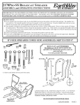
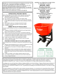
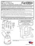
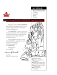
ASSEMBLY and OPERATING INSTRUCTIONS
®
EarthWay Ev-N-Spred
M24SSD Series Broadcast Spreader
PLEASE: CALL US IF YOU HAVE DIFFICULTY BEFORE YOU
RETURN THIS TO THE STORE.
PARTS HOT LINE PHONE: 574-848-7491
HELPFUL HINTS:
If your spreader does not spread evenly, be sure the FRONT on the gear box points to the front of the spreader. The impeller must
turn clockwise. Reversing the gearbox will cause the impeller to turn counter clockwise. Clean the impeller plate after each use.
Fertilizer stuck on the impeller blades will cause uneven spreading.
Your spreader is designed to be pushed at three miles per hour, which is a brisk walking speed. Slower or faster speeds will change
the spread patterns. Wet fertilizer will also change the spread pattern and flow rate. Clean your spreader thoroughly after each use.
Wash between the shut off plate and bottom of the hopper.
Gears are permanently lubricated at the factory. Do not open the gearbox or dirt may enter.
1. Remove and identify loose parts from carton.
2. Position hopper on side. Install frame using (4) 1/4-20
x 1-1/2” Pan Head Philips machine screws and (4) 1/4-20
nylon insert locknuts. First put bolts through holes in
frame then through holes in bottom of hopper. Secure
with locknuts. Tighten these locknuts now.
PAGE 1
3. Install impeller onto pinion shaft. Insert 1/8” x 1 ” cotter pin
through impeller then through pinion shaft. Use hole nearest gear box.
Spread cotter pin to prevent from falling out.
4. Install gear box by inserting the pinion shaft into hole in
center of hoppers bottom. The word “FRONT” on the gearbox
must point to Front of the hopper.
5. A - Install lower handles onto axle to both sides as shown.
Now insert 1 1/2” bolt through first hole in lower handle. Then
through frame brace. NOTE: Dimples on frame brace must be
facing toward gear box as shown. Next into threaded connector in
cross brace. DO NOT TIGHTEN YET. B - Next insert 1 1/2”
bolt through other end of frame brace and through second hole in
frame install locknut. DO NOT TIGHTEN YET. C - Now insert 2 1/4” bolt through second hole in lower handle and through
first hole in frame.
NOW GO BACK AND TIGHTEN ALL NUTS AND BOLTS STARTING WITH FIRST STEP. DO NOT OVER TIGHTEN.
PAGE 2
stall drive wheel to axle using pin
6. Inhole nearest to lower handles as shown. Insert 2” cotter pin through wheel and through axle. Bend with pliers to prevent pin from
falling out. Next slide the wheel spacer and then the outer wheel and cotter pin through the axle only.
7. Install inner coast wheel to axle, then wheel spacer and then the outer coast
wheel and install cotter pin using outside hole. As shown, insert 1” cotter pin
through axle (not thru the wheel). Bend with pliers to prevent pin from falling out.
TURN SPREADER UPRIGHT ON TO WHEELS.
8. NOTE: BEFORE INSTALLING GAUGE AND UPPER
HANDLES TO HANDLE SHAFT, UPPER HANDLES FEATURE THREE POSITIONS FOR OPERATOR’S COMFORT. You can select lower, middle or upper positions for best
fit to the operator. Insert 2¾” bolt through the Gauge, then upper
handle and finally through handle. DO NOT TIGHTEN
LOCKNUT YET.
9. Insert pivot rod into shut off plate as shown. Turn to lock in
place.
10. Insert other end of pivot rod into pivot and bracket assembly
as shown. Turn to lock in place.
PAGE 3
11. Install handle shaft to lower handles and pivot & bracket assembly as shown. Using (4) 1 ½” bolts and (4) locknuts.
Tighten bolts and nuts now.
13. Install flattened end of control rod in to lever on gauge as
12. Install (1) 1/4-20 regular nut (not a locknut) on to control rod as shown.
14. Pull lever back to setting “30” as shown. Next push pivot &
bracket forward so that the shut off plate in the hopper is in the full
open position. REMEMBER SETTING “30” ON THE FLOW
CONTROL LEVER MUST PLACE THE SHUT-OFF PLATE
IN THE FULL OPEN POSITION TO BE PROPERLY CALIBRATED. Now tighten the nuts against the pivot bracket to prevent
change in calibration.
shown. Turn to lock in place. Next push lever forward to setting
“0”. Align control rod with hole in pivot bracket, pull lever
backward to insert control rod through hole in pivot bracket.
Now install 1/4-20 regular nut on to control rod. DO NOT
TIGHTEN NUTS YET.
15. Insert large hair pin clip to pinion shaft on inside of hopper.
Note: Position of flat side of hair pin clip. This pin should be installed as shown.
PAGE 4
17.
For normal operation both plates should
be fully opened. To reduce flow to the left
side, partially or completely close the plate
over the rear (large) hole. To reduce flow to
the right side, partially or completely close
the plate over the front (small) hole. Close
both plates for a narrow center spread pattern. WARNING: If the optional side deflector is being used in the down position, the
plate over the rear (large) hole MUST BE
CLOSED or an over application of material
will occur.
16. Tension on the flow control lever may be adjusted
by tightening or loosening the tension nut as shown.
The settings furnished on the Rate Setting Chart are intended as a guide only. Variations in physical characteristics of material applied,
walking speed, and roughness of ground surface may require slightly different spreader settings. Due to the above conditions, EARTHWAY PRODUCTS, INC. makes no warranty as to the uniformity of coverage actually obtained from the settings listed.
WARRANTY
OPERATING INSTRUCTIONS
EARTHWAY guarantees this product to be free of defects in original workmanship and materials for a period of 90-days from sale to
the original user. If any defect develops during this period
EARTHWAY will repair or replace this product at no charge provided the defect is not the result of mishandling or tampering and
that this product is received at the factory with shipping charges
prepaid. For quicker service you may call EARTHWAY at 574848-7491 or write and describe the nature of the defect and we will
send repair parts to you. Due to the corrosive nature of most fertilizers and ice melters, EARTHWAY PRODUCTS, INC. makes no
warranty or guarantee against corrosion failure on models with
plated steel or painted steel frames. Clean your spreader well after
each use. Warranty covers parts only, but not labor charges.
Before filling hopper, become familiar with the operation of
this spreader.
Obtain proper setting for material to be used from the
RATE SETTING CHART included with this spreader.
Move stop bolt on rate gauge assembly to the proper
setting.
While pushing spreader forward, pull control lever back
to stop bolt.
To stop, push lever forward to close flow holes before
you stop moving.
When finished, empty any remaining material from hopper.
Thoroughly wash spreader and allow to dry before storing. No oiling is necessary.
DO NOT RETURN TO DEALER FOR REPAIR
HOW TO ORDER SPARE PARTS
EARTHWAY PRODUCTS, INC.
1009 Maple Street
P.O. Box 547
Bristol, IN 46507
FOR YOUR RECORDS
_________________________________________
Date Purchased
_________________________________________
Store Name
All spare parts listed herein may be ordered direct from the
manufacturer, EARTHWAY PRODUCTS, INC.
Be sure to give the following information when ordering.
1. Model Number
2. Part Number
3. Part Description
Call (574) 848-7491 or write for current prices.
PAGE 5
EarthWay
®
Products, Inc.
P.O. Box 547
Bristol, Indiana 46507
(574) 848-7491
www.earthway.com
Ke y #
1
2
3
4
5
6
7
8
9
11
12
13
14
15
16
18
21
22
24
Part #
40003
60219
33117
N/A
N/A
N/A
12209
12278
24202
N/A
42237
24704
24103
12109
N/A
60227
N/A
19117
N/A
De scription
Screen
Hopper Assembly, Includes Key #7 & 8
Agitator
*1/4-20 X 1 1/2" PHPMS SS
*1/4-20 NYLON Locknut
*1/4-20 X 1" Bolt
Hopper Bushing
New Pro Shut-Off Plate
Lower Handle W/Bearings C24SS Stainless
*1/4-20 X 1 1/2" Bolt
Frame Brace
Cross Brace
Frame C24SS
Impeller
*1/8" X 1" Cotter Pin
Gear Box & Axle Assembly
*3/16" X 2" Cotter Pin
Drive Wheel /Coast Wheel
*3/16" X 1" Cotter Pin
Ke y #
25
27
29
32
33
34
35
36
38
40
42
44
45
46
Part #
N/A
60299
N/A
44251
42256
24301
60298
N/A
12273
60070
77002
60060R
60166R
22609
12151
36223
38146
* Source
De scription
*1/4-20 X 2 1/4" Bolt
Pivot & Bracket Assembly
*1/4-20 Hex Nut
Pivot Rod
Control Rod
Handle Shaft C24SS
Gauge & Lever Assembly
*1/4-20 X 2 3/4" Bolt
Handle Grip
Upper Handle Assembly C24SS W/Grip
Optional Heavy Duty Rain Cover
Optional Heavy Duty Rain Cover & Side Deflector Kit
Optional Salt Deflector
Wheel Spacer M24SSD
Rectangle Shut Off Plate Washer
#6 x 1/2" Shut Off Plate Screw
Hardware Package M24SSD
locally, can be found in most hardware stores