1
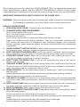
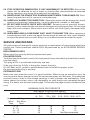
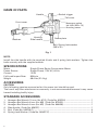
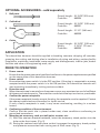
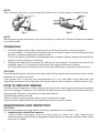
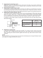
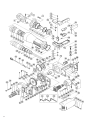
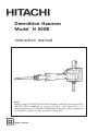
Demolition Hammer
Model H 90SB
Instruction manual
Note:
Before using this HITACHI Demolition Hammer, carefully read through this
INSTRUCTION MANUAL to ensure efficient, safe operation. It is
recommended that this INSTRUCTION MANUAL be kept readily available as
an important reference when using this power tool.
Double insulation
We sincerely thank you for selecting a HITACHI POWER TOOL. To operate this power tool
safely and efficiently, please read this INSTRUCTION MANUAL carefully to get a good
understanding of the precautions in operation, capacity of the power tool, use and the like.
IMPORTANT INFORMATION: SAFETY RULES FOR THE POWER TOOL
WARNING: When using the power tool, following basic safety precautions should always
be followed to reduce the risk of fire, electric shock, and personal injury.
READ ALL INSTRUCTIONS
1. KEEP WORK AREA CLEAN. Cluttered areas and benches invite injuries.
2. CONSIDER WORK AREA ENVIRONMENT.
Don’t expose power tools to rain.
Don’t use power tools in damp or wet locations.
Keep work area well lit.
Don’t use the power tool in presence of flammable liquids or gases.
Power tools produce sparks during operation. They also spark when switching ON/
OFF. Never use power tools in dangerous sites containing lacquer, paint, benzine,
thinner, gasoline, gases, adhesive agents, and other materials which are combustible
or explosive.
3. GUARD AGAINST ELECTRIC SHOCK. Prevent body contact with grounded surfaces.
For example: pipes, radiators, ranges refrigerator enclosures.
4. KEEP VISITORS OR CHILDREN AWAY. Do not let visitors or children contact the power
tool or extension cord. All visitors or children should be kept away from work area.
5. STORE IDLE POWER TOOLS. When not in use, power tools should be stored in dry,
and high or locked-up place-out of reach of children.
6. DON’T FORCE THE POWER TOOL. It will do the job better and safer at the rate for
which it was intended.
7. USE RIGHT POWER TOOLS. Don’t force a small power tool or attachment to do the job
of a heavy-duty tool. Don’t use the power tool for purpose not intended - for example don’t use circular saw for cutting tree limbs or logs.
8. DRESS PROPERLY. Do not wear loose clothes or accessories. They can be caught in
moving parts.
Rubber gloves and non-skid footwear are recommended when working outdoors.
Wear protective hair covering to contain long hair.
9. USE SAFETY GLASSES. All persons in the area where power tools are being operated
should also wear safety eye protectors, and face or dust masks if cutting operation is
dusty.
10. DON’T ABUSE CORD. Never carry power tools by cord or yank the cord to disconnect
the power tool from receptacle. Keep the cord from heat, oil and sharp edges.
11. DON’T OVERREACH. Keep proper footing and balance at all times.
12. MAINTAIN POWER TOOLS WITH CARE. Keep power tools sharp and clean for better
and safer performance.
Follow instructions for lubricating and changing accessories.
Inspect tool cords periodically and if damaged, have repaired by the authorized service
center.
Inspect extension cords periodically and replace them if damaged.
Keep handles dry, clean, and free from oil and grease.
1
13. DISCONNECT POWER TOOLS. When not in use, before servicing, and when changing
accessories, such as blades, bits, cutters.
14. REMOVE ADJUSTING KEYS AND WRENCHES. Form habit of checking to see that keys
and adjusting wrenches are removed from the power tool before turning it on.
15. AVOID UNINTENTIONAL STARTING. Don’t carry a plugged-in the power tool with finger
on switch. Be sure switch is off when plugging in.
16. OUTDOOR USE EXTENSION CORDS. When the power tool is used outdoors, use only
extension cords intended for use outdoors and so marked.
17. STAY ALERT. Watch what you are doing. Use common sense. Do not operate the power
tool when you are tired.
18. CHECK DAMAGED PARTS. Before use of the power tool, a guard or other part should
be carefully checked to determine that it will operate properly and perform its intended
function. Check the alignment of moving parts, binding of moving parts, breakage of
parts, mounting, and any other conditions that may affect its operation. A guard or
other part that is damaged should be properly repaired or replaced by an authorized
service center unless otherwise indicated elsewhere in this instruction manual.
Have defective switches replaced by an authorized service center.
Do not use the power tool if switch does not turn it on and off.
19. AVOID USING A POWER TOOL FOR APPLICATIONS OTHER THAN THOSE SPECIFIED.
Never use the power tool for applications other than those specified in this instruction
manual.
20. ENSURE SAFE OPERATION THROUGH CORRECT HANDLING. Secure safe operation
through correct handling by observing the instructions described herein.
Do not employ accessories other than those specified herein; otherwise, a hazardous
condition may be created.
Never allow the power tool to be used by persons not familiar with correct handling
(such as chidren) or by those who are not familiar with the power tool.
21. CONFIRM THAT NO ITEMS SUCH AS AN ELECTRIC CABLE OR CONDUIT ARE BURIED
INSIDE. In places where electric wiring may be hidden behind a wall, floor, ceiling, etc.
do not hold or contact any metal parts of the poweer tool. In such cases, metal parts
could become electrically live and present a serious shock hazard.
22. KEEP THE RIGHT PARTS IN THE RIGHT POSITIONS. Do not remove covers and screws
which have been factory-mounted. They perform important respective roles. Keep them
in the original positions.
23. SHOULD THE PLASTIC HOUSING OR HANDLE OF THE POWER TOOL BE CRACKED OR
DEFORMED, DO NOT USE IT. Since cracked or deformed parts may lead to an operator
receiving an electric shock, do not use such a power tool. Immediately have it repaired.
24. SECURELY MOUNT ACCESSORIES AND BLADES TO THE POWER TOOL MAIN BODY.
Extra care must be taken when using the power tool on elevated location (such as a
roof ladder, scaffold, or the like) to prevent injury to someone underneath in the event
the power tool and/or accessory should drop.
25. ALWAYS KEEP THE MOTOR AIR VENT FULLY OPENED. A constantly open motor air
vent is necessary to allow air to come in and out for cooling the motor. Do not allow it
to become clogged up, even if dust is blown through it.
26. OPERATE THE POWER TOOL AT THE RATED VOLTAGE. Operate the power tool at
voltages specified on its nameplate.
27. NEVER TOUCH THE MOVING PARTS. Never touch the moving parts such as blades,
bits, cutters and others.
2
28. STOP OPERATION IMMEDIATELY IF ANY ABNORMALITY IS DETECTED. Should the
power tool be detected as out of order or should other abnormalities be observed
during operation, stop using the power tool immediately.
29. NEVER LEAVE THE POWER TOOL RUNNING UNATTENDED. TURN POWER OFF. Don’t
leave the power tool until it comes to a complete stop.
30. CAREFULLY HANDLE THE POWER TOOL. Should the power tool be dropped or struck
against hard materials inadvertently, it may be deformed, cracked, or damaged.
31. DO NOT WIPE PLASTIC PARTS WITH SOLVENT. Solvents such as gasoline, thinner,
benzine, carbon tetrachloride, and alcohol damage and crack plastic parts. Do not wipe
them with such solvents. Wipe plastic parts with a soft cloth lightly dampened with
soapy water.
32. WHEN REPLACING A COMPONENT PART, ADOPT THE SAME TYPE. When replacing a
component part with a new one, adopt the same type of new part. Also, never attempt
to repair the power tool yourself. Bring it to an authorized service center for repair.
SERVICE AND REPAIRS
All quality tools will eventually require servicing or replacement of parts due to wear from
normal use. These operations should ONLY be performed by an AUTHORIZED SERVICE
CENTER.
REPLACEMENT PARTS
When servicing use only identical replacement parts.
POLARIZED PLUGS
To reduce the risk of electric shock, this equipment has a polarized plug (one blade is wider
than the other).
This plug will fit in a polarized outlet only one way.
If the plug does not fit fully in the outlet, reverse the plug.
If it still does not fit, contact a qualified electrician to install the proper outlet.
Do not change the plug in any way.
EXTENSION CORD
Make sure your extension cord is in good condition. When using an extension cord, be
sure to use one heavy enough to carry the current the power tool will draw. An undersized
cord will cause a drop in line voltage resulting in loss of power and overheating. Table
below shows the correct size to use depending on cord length and nameplate ampere
rating. If in doubt, use the next heavier gage. The smaller the gage number, the heavier the
cord.
MINIMUM GAGE FOR CORD SETS
Total Length of Cord in Feet (Meter)
0 – 25
(0 – 7.6)
Ampere
More
Than
Rating
Not More
Than
0–6
6 – 10
10 – 12
12 – 16
3
26 – 50
51 – 100
101 – 150
(7.9 – 15.2) (15.5 – 30.5) (30.8 – 45.7)
AWG
18
18
16
14
16
16
16
12
16
14
14
12
14
12
Not Recommended
DOUBLE INSULATION SYSTEM ENHANCES SAFE OPERATION
To enhance safe operation of this power tool, HITACHI has adopted a double insulation
system. The term “double insulation” used here denotes an insulation system with two
insulations physically separated and arranged between the electrically conductive material
connected to the power supply and the outer frame subject to contact
by the operator.
Thus, the power tool is termed double insulated and both the “ ”
mark and “Double insulation”, or either one is indicated on the name
plate.
DOUBLE INSULATION
While no external grounding is required with this system, normal safety
precautions as outlined in this manual must still be followed.
To maintain the effectiveness of the double insulation system, follow the precautions
described below:
1. Always contact your dealer or an authorized service center when assembling,
disassembling or replacing parts other than accessories or carbon brushes. Improper
assembly and/or replacement with wrong parts may result in eliminating the double
insulation-feature.
2. Clean the exterior of the power tool with a soft cloth moistened with soapy water, and
dry thoroughly. Chloric solvent, gasoline, and thinner will cause plastic components to
dissolve.
PARTICULAR PRECAUTIONS ON DEMOLITION HAMMER
In addition to the precautions mentioned above, following particular precautions for this
demolition hammer should be followed.
1. Use earplugs to keep your ears noise-free while working.
2. Wear protective shoes to protect your feet.
3. Properly set the bit holder.
4. Always hold the body handle and side handle of the power tool firmly. Otherwise the
counterforce produced may result in inaccurate and even dangerous operation.
5. Since the bit becomes very hot during operation, do not touch it because you are burnt.
6. At the start of work, confirm screw tightening.
7. When working at a highly elevated location, pay attention to articles and persons below.
SAVE THESE INSTRUCTIONS
AND
MAKE THEM AVAILABLE TO
OTHER USERS OF THIS POWER
TOOL!
4
NAME OF PARTS
Switch trigger
Handle
Tail cover
Front cover
Hexagon socket
hd. bolt (M5 x 10)
Housing cover
Housing
Retainer
Name plate
Side handle
Bolt, Spring lock washer
(M8 x 30)
Fig. 1
NOTE:
Install the side handle with the supplied 4 bolts and 4 spring lock washers. Tighten the
bolts securely with the supplied wrench.
SPECIFICATIONS
Motor
Power Source
Current
Full-Load Impact Rate:
Weight
Single-Phase, Series Commutator Motor
Single-Phase, 115V AC, 60 Hz
12.2A
850/min
68.4 lbs (31.0 kg)
ACCESSORIES
CAUTION:
Only following genuine accessories for this power tool should be used.
The use of any other attachment or accessory is not recommended because it may cause
hazard including bodily injury.
STANDARD ACCESSORIES
1.
2.
3.
4.
5.
6.
5
Hexagon Bar Wrench 10 mm (for M12) (Code No. 993740) ........................................... 1
Hexagon Bar Wrench 6 mm (for M8) (Code No. 872422) ............................................... 1
Hexagon Bar Wrench 4 mm (for M5) (Code No. 944458) ............................................... 1
Side Handle (Code No. 956527) ........................................................................................ 1
Bolt (Code No. 949759 Z) .................................................................................................. 4
Spring Lock Washer (Code No. 949457 Z) ....................................................................... 4
OPTIONAL ACCESSORIES…sold separately
1.
Bull point
Overall length: 20-15/32”(520 mm)
Code No.:
985230
2.
Cold chisel
Overall length: 20-15/32” (520 mm)
Code No.:
985231
3.
Scoop
Overall length: 21-1/2” (546 mm)
Code No.:
985233
4.
Cutter
Overall length: 20-15/32” (520 mm)
Width:
2-15/16” (75 mm)
Code No.:
985232
APPLICATION
This demolition hammer should be applied to breaking concrete, chipping off concrete,
grooving, bar cutting, and driving piles in installation of piping and wiring, sanitary facility
installation, machinery installation, water supply and drainage work, interior jobs, harbor
facilities and other civil engineering work, etc.
PRIOR TO OPERATION
1.
2.
3.
4.
5.
6.
Power source
Ensure that the power source to be utilized conforms to the power requirements specified
on the name plate of this demolition hammer.
Power switch
Ensure that the power switch is in the OFF position. If the plug is connected to a power
receptacle while the power switch is in the ON position, this demolition hammer will
start operating immediately, inviting serious accident.
Extension cord
When the work area is remote from the power source, use an extension cord of sufficient
thickness and rated capacity. The extension cord should be kept as short as practicable.
Confirm the power receptacle
If the power receptacle loosely accepts the plug, the receptacle must be repaired. Contact
the nearest authorized service center for repair service.
If such a faulty receptacle is used, it may cause overheating, resulting in a serious
hazard.
Confirming condition of the environment
Confirm that the work site is placed under neat, clean conditions conforming to
prescribed precautions.
Mounting an accessory, such as a bull point, a cutter, etc..
(1) With the retainer directed backward, insert the accessory shank portion into the
hole on the front cover. (Fig. 2)
(2) Swing the retainer back into place so that it engages the accessory shank portion
and prevents accessories from coming out of front cover. (Fig. 3)
6
NOTE:
Use a manual hammer to open/close the retainer as it is too heavy to move by hand.
Fig. 2
Fig. 3
NOTE:
When removing the accessory, such as a bull point, a cutter etc., follow the above procedure
in reverse order.
OPERATION
1.
2.
Pull the trigger switch after applying the tip of the bit to the crushing position.
In some cases, it is necessary to punch the tip of the bit against the crushing position
forcibly in order to begin the striking stroke.
This is not due to malfunction of the power tool. It means that the safe guard mechanism
against no-load striking is working.
Operate this demolition hammer by utilizing its own weight. The performance will not
be better even if it is pressed or thrust forcibly against the work surface.
Hold this demolition hammer with a force just sufficient to counteract the reaction.
CAUTION:
Sometimes the power tool does not begin the striking stroke even when the motor rotates
because oil has become thick.
If the power tool is used at low temperatures or if it is used after a long idle time, this
demolition hammer should be kept running for about five minutes in order to warm it up.
HOW TO REPLACE GREASE
This Demolition Hammer is full air-tight construction to protect against dust and to prevent
lubricant leakage. Therefore, this Demolition Hammer can be used without lubrication for
long periods. Replace the grease as described below.
Grease Replacement Period:
After purchase, replace grease after every 6 months of usage.
Ask for grease replacement at the nearest authorized service center.
MAINTENANCE AND INSPECTION
CAUTION:
Be sure to disconnect the plug before and during maintenance and inspection.
1. Inspecting this demolition hammer
Use of a dull accessory, such as a bull point, a cutter, etc., will cause motor
malfunctioning and efficiency degraded. Replace with a new one without delay when
abrasion is noted.
7
2.
3.
4.
Inspecting the mounting screws:
Regularly inspect all mounting screws and ensure that they are properly tightened.
Should any of the screws be loose, retighten them immediately. Failure to do so could
result in serious hazard.
Inspecting the retainer (Fig.2 and 3)
The retainer may become loose due to excessive use. Always, pay attention to its proper
functioning to securely hold the accessory shank portion. If any wear and tear is found,
bring this demolition hammer to an authorized service center for maintenance service.
Inspecting the carbon brushes: (Fig. 4)
The motor employs carbon brushes which are consumable parts. When they become
worn to or near “wear limit”, it results in motor trouble. When an auto-stop carbon
brush is equipped, the motor will stop automatically. At that time, replace both carbon
brushes with new ones which have the same carbon brush No. shown in the Fig. 4.
In addition, always keep carbon brushes clean and ensure that they slide freely within
the brush holders.
Wear limit
No. of Carbon
Brush
No. of
carbon brush
Usual carbon brush
44
Auto-stop carbon
brush
74
Fig. 4
5.
Replacing a carbon brush
Loose the screw (Hexagon socket hd. bolt M5 x 10) of the tail cover, then remove the
tail cover. (Fig. 1) After removing the brush cap, the carbon brush can be removed.
After replacing the carbon brush, tighten the brush cap, then mount the tail cover
securely.
NOTE:
Due to HITACHI’s continuing program of research and development, the specifications herein
are subject to change without prior notice.
8
9
Item
No.
1
2
3
4
5
6
7
8
9
10
11
12
13
14
15
16
17
18
19
20
21
22
23
24
25
26
27
28
29
30
31
32
33
34
35
36
37
38
39
40
41
42
43
44
45
46
47
48
49
50
51
52
53
54
55
56
57
Part Name
Roll Pin
Lever Pin
Bolt
Retainer
Front Cover
O-Ring (S-90)
O-Ring
Second Hammer
O-Ring (D)
O-Ring (A)
Hammer Holder
Hexagon Socket Hd. Bolt
Stopper Washer
Handle (A)
Rubber Leg
Cord Clip
Tapping Screw
Handle Rubber
Handle (B)
Switch
Support
Hexagon Socket Hd. Bolt
E-Type Retaining Ring
Switch Lever
Pin
Internal Wire Holder
Brush Cap
Carbon Brush
Brush Holder
Stop Plate
Damper
Damper Plate
Mouth
Mouth Washer
Urethane Ring
Cylinder Case
Bolt
Washer
O-Ring
Striker
O-Ring (B)
Piston Pin
Piston
Oil Seal (A)
Connecting Rod Ass’y
Needle Bearing
Cord
Tube (D)
Cor d Armor
Vinyl Tube (A) (I.D.7 x T 0.5 x 50)
Terminal
Ball Bearing (6305ZZCM)
Oil Seal
O-Ring
Bearing Boss
Spring Lock Washer
Hexagon Socket Hd. Bolt
D6 × 36
M12 × 40
M6 × 16
D4 × 20
M6 × 16
M10 × 45
M6 × 20
Item
No.
58
59
63
64
65
66
67
68
69
70
71
72
73
74
75
76
77
78
79
80
81
82
83
84
85
86
87
88
89
90
91
92
93
94
95
96
97
98
99
100
101
102
103
104
105
106
107
108
109
110
111
112
501
502
503
Part Name
Crank Washer
Hexagon Socket Hd. Bolt
Connector
Connector
Internal Wire
Hexagon Socket Hd. Bolt
Hexagon Socket Hd. Bolt
Spring Lock Washer
Side Handle
Ball Bearing (6204VVCM)
Distance Washer
Final Gear
Distance Ring (B)
Inner Cover
Housing Ass’y
O-Ring (S-38)
Oil Cap
Tail Cover
Spring Lock Washer
Hexagon Socket Hd. Bolt
Rivet
Name Plate
Hexagon Socket Hd. Bolt
Gear Cover
Ball Bearing (6201VVCM)
Counter Gear
Hexagon Socket Hd. Bolt
Bearing Cover (A)
Needle Bearing (BK1312)
Ball Bearing (6203VVCM)
Bearing Washer
Pin
Feather Key
Crank Shaft
Friction Piece
Hexagon Socket Hd. Sect Screw
Fan
Armature
Hexagon Hd. Tapping Screw
Special Washer
Internal Wire
Stator
Brush Terminal
Vinyl tube (B)(I.D.4 × T0.4 × 80)
Bearing Washer
Ball Bearing (6201VVCM)
HITACHI Label
Housing Cover
Collar
Bolt Washer
Spring Lock Washer
Hexagon Socket Hd. Bolt
Hexagon Bar Wrench
Hexagon Bar Wrench
Hexagon Bar Wrench
M10 × 16
M10 × 60
M8 × 30
M5 × 10
D2.5 × 4.8
M10 × 55
M5 × 14
B8 × 14
4 × 4 × 15
M5 × 8
D5 × 85
M6 × 20
4 mm
6 mm
10 mm
Parts are subject to possible modification without notice due
to improvements.
10
WARNING:
Some dust created by power sanding, sawing, grinding, drilling, and other construction
activities contains chemicals known to the State of California to cause cancer, birth
defects or other reproductive harm. Some examples of these chemicals are:
• Lead from lead-based paints,
• Crystalline silica from bricks and cement and other masonry products, and
• Arsenic and chromium from chemically-treated lumber.
Your risk from these exposures varies, depending on how often you do this type of
work. To reduce your exposure to these chemicals: work in a well ventilated area, and
work with approved safety equipment, such as those dust masks that are specially
designed to filter out microscopic particles.
Issued by
Shinagawa Intercity Tower A, 15-1, Konan 2-chome,
Minato-ku, Tokyo 108-6020, Japan
Distributed by
3950 Steve Reynolds Blvd.
Norcross, GA 30093
itachi6395
Koki
Canada Co.
Kestrel Road
Mississauga ON L5T 1Z5
302
Code No. C99006764 N
Printed in Japan