1
INSTRUCTIONS-PARTS LIST
307–586
Rev. P
Supersedes M
and PCN P
This manual contains important
warnings and information.
READ AND KEEP FOR REFERENCE.
INSTRUCTIONS
HIGH PRESSURE AIR-ASSISTED AIRLESS
Model AA 2000 Spray
Gun
950 psi (66 bar) Maximum Working Fluid Pressure
100 psi (7 bar) Maximum Working Air Pressure
Part Number 217–292, Series C
Includes spray tip of choice.
U.S. Patent Nos. 3,843,052; 4,386,739
United Kingdom Patent No. 2 111 406 B
Patented 1984 Canada
Brevete 1984
French Patent No. 82–21202
Foreign Patents Pending
Table of Contents
Warnings . . . . . . . . . . . . . . . . . . . . . . . . . . . . . . . . . . . . . . 2
Installation . . . . . . . . . . . . . . . . . . . . . . . . . . . . . . . . . . . . 4
Operation . . . . . . . . . . . . . . . . . . . . . . . . . . . . . . . . . . . . . 7
Troubleshooting . . . . . . . . . . . . . . . . . . . . . . . . . . . . . . . 12
Service . . . . . . . . . . . . . . . . . . . . . . . . . . . . . . . . . . . . . . 14
Parts . . . . . . . . . . . . . . . . . . . . . . . . . . . . . . . . . . . . . . . . 16
Spray Tip and Air Cap Selection Charts . . . . . . . . . . 18
Accessories . . . . . . . . . . . . . . . . . . . . . . . . . . . . . . . . . . 20
Technical Data . . . . . . . . . . . . . . . . . . . . . . . . . . . . . . . . 21
Dimensions . . . . . . . . . . . . . . . . . . . . . . . . . . . . . . . . . . . 21
Warranty . . . . . . . . . . . . . . . . . . . . . . . . . . . . . . . . . . . . . 24
Graco Phone Number . . . . . . . . . . . . . . . . . . . . . . . . . . 24
GRACO INC.
P.O. BOX 1441 MINNEAPOLIS, MN
COPYRIGHT 1982, GRACO INC.
Graco Inc. is registered to I.S. EN ISO 9001
55440–1441
WARNING
INJECTION HAZARD
Spray from the gun, hose leaks, or ruptured components can inject fluid into your body and cause an
extremely serious injury, including the need for amputation. Splashing fluid in the eyes or on the skin
can also cause a serious injury.
Fluid injected into the skin might look like just a cut, but it is a serious injury. Get immediate medical attention.
Do not point the spray gun at anyone or at any part of the body.
Do not put hand or fingers over the spray tip.
Do not stop or deflect fluid leaks with your hand, body, glove, or rag.
Do not “blow back” fluid; this is not an air spray gun.
Check the gun diffuser operation weekly.
Be sure the gun trigger safety operates before spraying.
Lock the gun trigger safety when you stop spraying.
Follow the Pressure Relief Procedure on page 7 whenever you: are instructed to relieve pressure; stop spraying; clean, check, or service the equipment; or install or clean the spray tip.
Tighten all the fluid connections before operating the equipment.
Check the hoses, tubes, and couplings daily. Replace worn, damaged, or loose parts immediately.
Permanently coupled hoses cannot be repaired; replace the entire hose.
FIRE AND EXPLOSION HAZARD
Improper grounding, poor air ventilation, open flames, or sparks can cause a hazardous condition and
result in fire or explosion and serious injury.
Ground the equipment and the object being sprayed. See Ground the System on page 6.
Provide fresh air ventilation to avoid the buildup of flammable fumes from solvent or the fluid being
sprayed.
Extinguish all the open flames or pilot lights in the spray area.
Electrically disconnect all the equipment in the spray area.
Keep the spray area free of debris, including solvent, rags, and gasoline.
Do not turn on or off any light switch in the spray area while operating or if fumes are present.
Do not smoke in the spray area.
Do not operate a gasoline engine in the spray area.
If there is any static sparking while using the equipment, stop spraying immediately. Identify and
correct the problem.
WARNING
EQUIPMENT MISUSE HAZARD
INSTRUCTIONS
Equipment misuse can cause the equipment to rupture, malfunction, or start unexpectedly and result
in serious injury.
D This equipment is for professional use only.
D Read all instruction manuals, tags, and labels before operating the equipment.
D Use the equipment only for its intended purpose. If you are uncertain about usage, call your Graco
distributor.
D Do not alter or modify this equipment. Use only genuine Graco parts and accessories.
D Check the equipment daily. Repair or replace worn or damaged parts immediately.
D Do not exceed the maximum working pressure of the lowest rated system component. This equipment has a 950 psi (66 bar) maximum working pressure at 100 psi (7 bar) maximum incoming air pressure.
D Route the hoses away from the traffic areas, sharp edges, moving parts, and hot surfaces. Do not
expose Graco hoses to temperatures above 180_F (82_C) or below –40_F (–40_C).
D Do not use the hoses to pull the equipment.
D Fluid hoses must have spring guards on both ends to protect them from rupture caused by kinks or
bends near the couplings.
D Use fluids or solvents that are compatible with the equipment wetted parts. See the Technical
Data section of all the equipment manuals. Read the fluid and solvent manufacturer’s warnings.
D Wear hearing protection when operating this equipment.
D Comply with all applicable local, state and national fire, electrical and other safety regulations.
TOXIC FLUID HAZARD
Hazardous fluids or toxic fumes can cause serious injury or death if splashed in the eyes or on the
skin, swallowed, or inhaled.
D Know the specific hazards of the fluid you are using. Read the fluid manufacturer’s warnings.
D Store hazardous fluid in an approved container. Dispose of hazardous fluid according to all local,
state and national guidelines.
D Wear the appropriate protective clothing, gloves, eyewear and respirator.
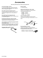
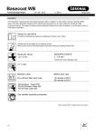
Installation
C
D
A
C
J
B
T
P
KEY
A
B
C*
D
E*
F
G
H*
J
K
L
M
N
P
Q
R
S
T
V*
W
X
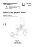
Air Line Filter
Air Line Lubricator
Bleed–type Master Air Valve
Pump Air Regulator
Fluid Drain Valve
Fluid Shutoff Valve
Fluid Filter
Grounded Fluid Hose
Pump
Air Line
Air Pressure Regulator
Pump Fluid Inlet
In–line Fluid Filter
Pattern Adjustment Valve Knob
Fluid Pressure Regulator
Pressure Gauge
Trigger Safety
Pump Runaway Valve
Ground Wire
Gun Fluid Connector
Air Shutoff Valve
V
Q
L
R
S
F
W
N
X
G
K
E
H
M
*Equipment required for safe operation of the
system. Must be purchased separately.
Fig. 1
Typical Installation
The typical installation shown in Fig. 1 is only a guide
for selecting and installing air-assisted airless spray
systems. It is not an actual system design. Contact
your Graco distributor for assistance in designing a
system to meet your needs.
The Graco fluid pump Model 217–523 is designed for
use in high pressure air-assisted airless systems. It
has a maximum working pressure of 950 psi (66 bar).
See instruction manual 307–595 for information on this
pump.
Ventilate the Spray Booth
WARNING
TOXIC FLUID HAZARD
To prevent hazardous concentrations of
toxic and/or flammable vapors, spray
only in a properly ventilated spray booth.
Never operate the spray gun unless ventilation
fans are operating.
Check and follow all of the National, State and
Local codes regarding air exhaust velocity requirements.
Installation
Connect the Air Line
1. Install an air line filter (A) to ensure a clean, dry air
supply to the gun. Dirt and moisture in the line can
ruin the appearance of your finished piece. See
Fig. 1.
2. Install an air pressure regulator (L) on the gun air
supply line to control the air pressure to the gun.
3. Install an air pressure regulator (D) on the pump
air supply line to control air pressure to the pump.
4. Install a bleed-type air shutoff valve (C) on the
main air line and on the pump air line, downstream
of the pump air regulator, to shut off air to the
pump. Install an additional bleed-type valve on
each pump air supply line to relieve air trapped
between this valve and the pump after the air
regulator is shut off.
WARNING
The bleed-type air shutoff valve is required in your
system to relieve air trapped between this valve
and the pump after the air regulator is closed.
Trapped air can cause the pump to cycle unexpectedly, which could result in serious injury.
NOTE: The gun air inlet has a 1/4–18 npsm (R1/4–19)
compound male thread that is compatible with NPSM
and BSP female swivel connectors.
5. Install an air shutoff valve (X) on each gun air
supply line, downstream of the gun air regulator, to
shut off air to the gun(s).
6. Connect the air hose (K) from the air supply to the
gun air inlet.
Connect the Fluid Line
WARNING
INJECTION HAZARD
To reduce the risk of property damage or
serious injury, including fluid injection,
which could be caused by component
rupture or unrelieved fluid pressure,
A fluid drain valve(s) (E) is required in your
system to assist in relieving fluid pressure in the
displacement pump, hose and gun; triggering
the gun to relieve pressure may not be sufficient.
A fluid pressure regulator (Q) must be installed
in the system if the pump’s maximum working
pressure exceeds the gun’s maximum fluid
working pressure of 950 psi (66 bar).
1. Install a fluid filter (G) and drain valve(s) (E) close
to the pump’s fluid outlet. The drain valve assists
in relieving fluid pressure in the displacement
pump, hose, and gun. See Fig. 1.
2. Install a fluid pressure regulator (Q) to control fluid
pressure to the gun.
NOTE: Some applications require fine-tuned control of
fluid pressure. You can control fluid pressure more
accurately with a fluid pressure regulator than by
regulating the air pressure to the pump.
3. Install a fluid shutoff valve (F) to shut off the fluid
supply to the gun.
4. Install fluid drain valve(s) (E) close to the pump’s
fluid outlet.
NOTE: The gun fluid fitting (W) has a 1/4–18 npsm
(R1/4–19) compound male thread that is compatible
with NPSM and BSP female connectors.
5. Install an in-line fluid filter (N) on the gun fluid
fitting (W) to avoid clogging the spray tip with
particles from the fluid.
6. Connect the grounded fluid hose (H) to the gun
fluid fitting (W) or optional in-line filter (N).
Installation
Ground the System
WARNING
FIRE AND EXPLOSION HAZARD
Improper grounding could cause static
sparking, which could cause a fire or
explosion. To reduce the risk of property
damage or serious injury, follow the
grounding instructions below.
The following grounding instructions are minimum
requirements for a system. Your system may include
other equipment or objects which must be grounded.
Check your local electrical code for detailed grounding
instructions for your area and type of equipment. Your
system must be connected to a true earth ground.
1. Pump: Ground the pump by connecting a ground
wire and clamp between the fluid supply and a true
earth ground as instructed in your separate pump
instruction manual.
2. Air compressors and hydraulic power supplies: Ground them according to the manufacturer
recommendations.
3. Air, fluid, and hydraulic hoses connected to
the pump: Use only grounded hoses with a maximum of 500 feet (150 m) combined hose length to
ensure grounding continuity. Check the electrical
resistance of your air and fluid hoses at least once
a week. If the resistance exceeds the recommended limits, replace the hose immediately.
4. Spray gun: Ground the gun by connecting it to a
properly grounded fluid hose and pump.
5. Fluid supply container: Ground it according to
local code.
6. Object being sprayed: Ground it according to
local code.
7. All solvent pails used when flushing: Ground
them according to local code. Use only metal pails,
which are conductive. Do not place the pail on a
non-conductive surface, such as paper or cardboard, which interrupts the grounding continuity.
8. To maintain grounding continuity when flushing or relieving pressure: Always hold a metal
part of the gun firmly to the side of a grounded
metal pail, then trigger the gun.
Operation
6. Lock the gun trigger safety again.
Safety
WARNING
INJECTION HAZARD
Remember, this is not an air spray gun.
For your safety be sure to read and
follow the Warnings on pages 2 and 3
and throughout the text of this instruction manual.
Keep the wallet sized warning card 179–960,
provided with the gun, with the operator of this
equipment at all times. The card contains important
treatment information should an injection injury
occur. Additional cards are available at no charge
from Graco.
Pressure Relief Procedure
7. Open the pump drain valve (required in the system) to help relieve fluid pressure in the displacement pump. In addition, open the drain valve
connected to the fluid pressure gauge (in a system
with fluid regulation) to help relieve fluid pressure
in the hose and gun. Triggering the gun to relieve
pressure may not be sufficient. Have a container
ready to catch the drainage.
8. Leave the drain valve(s) open until you are ready
to spray again.
9. If you suspect that the spray tip or hose is completely clogged or that pressure has not been fully
relieved after following the steps above, very
slowly loosen the hose end coupling and relieve
pressure gradually, then loosen the coupling
completely. Now clear the tip or hose obstruction.
INJECTION HAZARD
The system pressure must be manually
relieved to prevent the system from
starting or spraying accidentally. Fluid
under high pressure can be injected through the
skin and cause serious injury. To reduce the risk of
an injury from injection, splashing fluid, or moving
parts, follow the Pressure Relief Procedure
whenever you:
are instructed to relieve the pressure,
stop spraying,
check or service any of the system equipment,
or install or clean the spray tip.
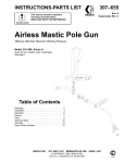
1. Lock the spray gun trigger safety to avoid accidentally triggering the gun. See Fig. 2.
Trigger Safety
Unlocked or in OFF
SAFE Position
2. Shut off the power to the pump.
3. Close the bleed-type master air valve (required in
the system).
Trigger Safety Locked
or in ON SAFE Position
4. Unlock the gun trigger safety.
5. Hold a metal part of the gun firmly to the side of a
grounded metal waste container and trigger the
gun to relieve the fluid pressure.
Fig. 2
Operation
How the Air-Assisted Airless Spray Gun
Operates
The air-assisted airless spray gun combines airless
and air spraying concepts. The spray tip shapes the
fluid into a fan pattern, as does a conventional airless
spray tip. Air from the air cap further atomizes the fluid
and completes the atomization of the paint tails into
the pattern to produce a more uniform pattern. The
pattern adjustment valve controls the width of the
pattern.
Note that the air-assisted airless spray gun differs from
an air spray gun in that increasing the pattern air
reduces the pattern width. To increase the pattern
width, less pattern air or a larger size tip must be used.
The spray gun has a built-in lead and lag operation.
When triggered, the gun begins emitting air before the
fluid is discharged. When the trigger is released, the
fluid stops before the air flow stops. This helps assure
the spray is atomized and prevents fluid buildup on the
air cap.
Select a Spray Tip and Air Cap
The fluid output and pattern width depend on the size
of the spray tip, the fluid viscosity, and the fluid pressure. Use the Spray Tip and Air Cap Selection
Charts, on pages 18 and 19, as a guide for selecting
an appropriate spray tip and air cap for your application.
NOTE:
When spraying at fluid pressures below 500 psi (35
bar) or spraying light viscosity fluids, use optional
fluid needle 220–413 (see page 20). The standard
needle may not provide positive shut off at those
pressures or for such fluids.
When spraying acid catalyzed varnishes, use
optional fluid needle 222–497 (see page 20). Using
a standard needle may decrease needle life and
leakage may occur.
Install a Spray Tip
WARNING
INJECTION HAZARD
To reduce the risk of a fluid injection
injury, follow the Pressure Relief Procedure on page 7 before removing or
installing a spray tip.
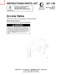
Install a spray tip in the gun. The air cap and spray tip
position determines the direction of the spray pattern.
Rotate the air cap (the spray tip rotates with it) as
needed for the desired spray pattern direction. See
Fig. 3.
Vertical Spray Pattern
Using a Fine Finish Spray Tip may improve the
finish of certain urethanes, clearcoats, or lightweight air-dry enamels. Refer to the Fine Finish
Spray Tip Selection Chart on page 19.
If you are applying a solid stream of fluid, such as
mastics or sealants, refer to the Solid Stream
Spray Tip Selection Chart on page 19.
Fig. 3
Horizontal Spray Pattern
Operation
Pattern
Adjustment
Knob
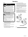
Adjust the Spray Pattern
WARNING
INJECTION HAZARD
To reduce the risk of component rupture
and serious injury, including injection, do
not exceed the gun’s maximum fluid
working pressure of 950 psi (66 bar) or the maximum working pressure of the lowest rated component in the system.
Fig. 4
NOTE: Optional gun parts are available for special
applications. See page 20.
1. Set the fluid pressure at 300 psi (21 bar) with the
fluid regulator.
2. Trigger the gun to check the atomization; do not be
concerned about the pattern shape yet.
3. Increase the fluid pressure just to the point where
a further increase in fluid pressure does not significantly improve fluid atomization.
4. Close the pattern adjustment valve by turning the
knob (see Fig. 4) counterclockwise all the way.
This sets the gun for its widest pattern.
No Air
Too Little Air
Right Amount
of Air
Fig. 5
5. Set the atomizing air pressure at about 20 psi (1.4
bar). Check the spray pattern, then adjust the air
pressure until the tails are completely atomized
and pulled into the spray pattern. See Fig. 5. Do
not exceed 100 psi (7 bar) air pressure to the gun.
For a narrower pattern, turn the pattern adjustment
valve knob clockwise. If the pattern is still not
narrow enough, increase the air pressure to the
gun slightly or use a different size tip.
RIGHT
NOTE: For some spray tips, when the line air pressure
to the gun is increased to a certain level, the spray
pattern will become round. This is the smallest pattern
width. Further increases in air pressure will force the
pattern to turn from horizontal to vertical or from vertical to horizontal.
Apply the Fluid
When applying the fluid, keep the gun a consistent
distance, 8 to 10 inches (200 to 250 mm), from the
surface of the object being sprayed. Always hold the
gun at a right angle from the surface. Do not make an
arc with the gun as it causes an uneven coat of fluid.
See Fig. 6.
WRONG
Fig. 6
Operation
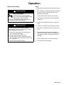
Clean the Spray Gun and System Daily
Check the Diffuser-seat Operation Weekly
WARNING
INJECTION HAZARD
To reduce the risk of an injection injury
or splashing fluid in the eyes or on the
skin:
Follow the Pressure Relief Procedure on page
7 before cleaning, removing, or installing a
spray tip and whenever you are instructed to
relieve pressure.
Do not wipe fluid buildup off the gun or spray tip
until pressure is relieved.
CAUTION
WARNING
INJECTION HAZARD
The gun diffuser-seat breaks up spray
when the gun is sprayed without the
spray tip installed, such as during flushing. This reduces the risk of an injection injury.
Check the diffuser-seat operation weekly.
1. Relieve the pressure as instructed on page 7.
2. Remove the tip guard and spray tip.
3. Start the pump and operate it at its lowest pressure.
To avoid damaging the gun:
Never immerse the gun in solvent as this could
damage packings and allow solvent in the air
passages.
Do not use metal tools to clean holes in the air
cap or spray tip.
4. Hold a metal part of the gun firmly against a
grounded metal waste container, and trigger the
gun. See Fig. 7. If the fluid coming from the gun is
not diffused into an irregular stream, replace the
diffuser-seat immediately.
NOTE: Clean the front of the tip frequently during the
day to help reduce buildup.
1
1. Relieve the pressure as instructed on page 7.
ÄÄÄÄ
ÄÄÄÄ
ÄÄÄÄ
2. Clean the outside of the gun and the tip guard with
a soft cloth dampened with compatible solvent.
3. To avoid damaging the spray tip and air cap, clean
them with a compatible solvent and soft brush. To
clean the air cap passages, use a soft brush or
other soft tool, with an air blow gun.
4. If using an in-line filter, remove and clean it
thoroughly in a compatible solvent.
5. Clean the system’s fluid filter and air line filter.
1
Maintain firm metal-to-metal contact between the gun and a
grounded metal container.
Fig. 7
Operation
Flush the Gun Daily
WARNING
INJECTION HAZARD
To reduce the risk of a fluid injection
injury, follow the Pressure Relief Procedure on page 7 before cleaning,
removing, or installing a spray tip and whenever
you are instructed to relieve pressure.
NOTE:
Flush the pump and gun before the fluid can dry in
it.
If it is available, the flushing procedure provided in
the pump or sprayer manual should be used
instead of this procedure.
1. Relieve the pressure as instructed on page 7.
2. Disconnect the atomizing air hose and the fluid
supply line.
3. Remove the tip guard and spray tip. Clean the
parts.
WARNING
4. Connect a compatible solvent supply to the gun.
To reduce the risk of serious injury, including
splashing fluid in the eyes or on the skin, or static
electric discharge when flushing:
5. Start the pump and operate it at its lowest pressure.
Be sure the entire system, including flushing
pails, are properly grounded.
Remove the tip guard and spray tip.
Maintain metal-to-metal contact between the
gun and a grounded metal waste container. See
Fig. 7, page 10.
Use the lowest possible pressure.
6. Hold a metal part of the gun firmly against a
grounded metal waste container, and trigger the
gun until all the paint is removed from the gun
passages.
7. Relieve the pressure as instructed on page 7.
8. Disconnect the solvent supply.
307-586 11
Troubleshooting
WARNING
INJECTION HAZARD
To reduce the risk of a fluid injection
injury, follow the Pressure Relief Procedure on page 7 before checking or
servicing any of the system equipment and whenever you are instructed to relieve pressure.
NOTE:
Check all possible remedies in the troubleshooting
charts before disassembling the gun.
Some improper patterns are caused by the
improper balance between air and fluid.
General Troubleshooting
Problem
Cause
Solution
Fluid leakage from back of fluid
needle
Worn packings (47) or needle (5)
shaft
Replace packings or needle. See
page 14.
Air leakage from front of gun
Air valve (52) not seating properly
Clean/service air valve. See page 14.
Fluid leakage from front of gun
Fluid needle (5) worn or damaged
Replace fluid needle. See page 14.
Worn diffuser-seat (30) housing
Replace the diffuser-seat and gasket
(33). The gasket must be replaced
whenever the diffuser-seat is removed. See page 14.
Fluid tip (28) seal leaking
Tighten or replace fluid tip.
Leaking around diffuser-seat (30)
housing
Replace the diffuser-seat gasket (33).
The gasket must be replaced whenever the diffuser-seat is removed.
See page 14.
Fluid inlet fitting (67) leaking
Replace the fluid fitting gasket (33).
The gasket must be replaced whenever the fluid fitting is removed. See
page 15.
Fluid in air passages
Spray Pattern Troubleshooting
Problem
Cause
Solution
Fluttering or spitting spray
Insufficient fluid supply
Adjust fluid regulator or fill fluid supply
tank.
Air in paint supply line
Check, tighten siphon hose connections, bleed air from paint line.
Fluid build-up or spray tip partially
plugged
Clean spray tip. See page 10.
On defective side of pattern, air horn
holes are partially or totally plugged
Clean air horn holes with solvent and
soft brush. See page 10.
Air horn holes partially or totally
plugged
Clean air horn holes with solvent and
soft brush. See page 10.
Irregular pattern
Pattern pushed to one side, same
side of air cap gets dirty
12ą307-586
Notes
307-586 13
Service
WARNING
INJECTION HAZARD
To reduce the risk of a fluid injection
injury, follow the Pressure Relief Procedure on page 7 before checking or
servicing any of the system equipment and whenever you are instructed to relieve pressure.
Fluid Packing Replacement
Follow the procedure below to remove the fluid packings for cleaning or replacement and to inspect the
needle shaft when there is leakage from the back of
the needle.
1. Relieve the pressure as instructed on page 7.
NOTE:
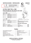
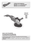
2. Remove the air cap retainer (25), air cap (27),
spray tip (28), and air separator (32). See Fig. 8.
D Follow the Service Notes in Fig. 8 when reassembling the gun. Also refer to the parts drawing on
page 16 for parts not shown in Fig. 8.
3. Trigger the gun to back the fluid needle ball off the
seat. Remove the diffuser-seat (30*) and gasket
(33*). Install a new gasket.
D Gun Repair Kit 224–949 is available. See page 17.
The reference numbers with asterisks in the service
procedures are included with the kit.
4. Remove the trigger (3). See the Parts Drawing,
page 16.
Air Valve Service
5. Remove the hex nut (21*) from the fluid needle
(5*), while holding the square part of the fluid
needle.
1. Relieve the pressure as instructed on page 7.
2. Remove the trigger (3) and valve cap (11). See the
parts drawing and Fig. 8.
3. Unscrew the needle nut (49) while holding the flats
of the air valve (52*) stem with a long nose pliers.
CAUTION
To avoid leakage, be careful not to scratch the air
valve stem.
4. Remove the spring (10*) and air valve (52*).
5. If there is air leakage at the air valve (52), unscrew
the packing nut (50) and carefully remove the
u-cup packing (51*). Replace the packing if it is
worn or damaged. When re-installing, be sure the
u-cup faces inward.
6. If leakage occurs internally or the front of the gun
leaks air when it is not triggered, clean and inspect
the air valve and the spring for wear or damage.
Replace as needed.
7. For the best air valve life, lubricate the external air
valve shaft (point A) with light oil after each day’s
use.
14ą307-586
6. Pull the fluid needle (5) and compression spring
(24*) from the front of the gun.
7. To remove the old packings (47*), insert the packing tool (55*) into the front of the gun and screw it
into the packings. Pull the packings from the front
of the gun.
8. Clean the parts with a compatible solvent and a
soft brush. Inspect the fluid needle (5) for wear or
damage, and replace it if necessary.
9. Insert the new packings (47) onto the fluid needle
(5) shaft as shown in Detail D of Fig. 8.
10. Install the fluid needle (5). Do not damage the
packings.
11. Screw the hex nut (21) all the way onto the fluid
needle (5). Do not over-tighten it.
12. Install the trigger.
13. Trigger the gun while screwing the diffuser-seat
(30) back into the gun. Torque the diffuser-seat to
23 to 27 ft-lbs (31 to 37 NSm).
14. Install the air separator (32), spray tip (28), air cap
(27), and air cap retainer (25).
Service
11
4
7
7
11
5
11
4
10
52
51
25
8
32
6
A
26
50
49
21
28
47
See DETAIL D
24
27
33
1
3
9
30
2
2
33
5
FLUID
9
67
DETAIL D
10
4
AIR
Fluid Needle
Packings (47)
SERVICE NOTES:
1
Diffuser-seat gasket (33) must be replaced if diffuser-seat (30)
is removed or replaced to avoid fluid leakage
2
Fluid fitting gasket (33) must be replaced if fluid fitting (67) is
removed or replaced to avoid fluid leakage
3
Lubricate threads
4
Apply anaerobic pipe sealant to threads
5
Apply high strength sealant to threads
6
Do not lubricate
7
Lubricate with light-weight oil
8
U-cup lips face inward
9
Torque to 23–27 ft-lb (31–37 Nm)
10
Torque to 20–24 ft-lb (27–32 Nm)
11
Torque to 15–19 ft-lb (20–26 Nm)
Fig. 8
307-586 15
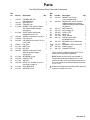
Parts
7
*62
18
*26
*63
11
28
10*
*21
27
52*
25
19
*51
*47
*24
20
*5
4
50
*33
2
49
67
3
33*
30*
3
2
1
32
66
55*
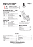
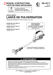
SERVICE NOTES (See Fig. 8 for additional information):
33
1
5
For Direct Hose Connection
(Parts shipped unassembled)
1
Lubricate threads
2
Torque to 23–27 ft-lb (31–37 Nm)
3
Diffuser-seat gasket (33) must be replaced if diffuser-seat (30) is removed or
replaced to avoid fluid leakage.
4
Fluid fitting gasket (33) must be replaced if fluid fitting (67) is removed or
replaced to avoid fluid leakage.
5
Torque to 10–14 ft–lb (14–19 Nm)
Parts
Use Only Genuine Graco Parts and Accessories
Ref.
No.
Part No.
1
178–415
2
3
5*
7
10*
11
18
19
20
21*
24*
25
26*
27
28
30*
32
Description
Qty.
CONNECTOR, fluid
(not assembled)
106–917 ADAPTER, air
178–454 TRIGGER, gun
217–488 NEEDLE, fluid; Optional Plastic
Ball Tipped Needle available,
see page 20
217–489 VALVE, pattern adjustment;
Includes items 62 & 63
106–903 SPRING, compression, air valve
178–408 CAP, valve, air
203–953 CAP SCREW, hex head, 10–24 x
0.375” long
160–217 PIN, pivot
217–516 BODY, gun
177–528 NUT, hex
109–022 SPRING, compression, fluid;
Optional Spring available,
see page 20
217–526 RETAINER, air cap
107–079 O-RING, PTFE r
217–303 AIR CAP
182–XXX SPRAY TIP; Customer’s choice.
See Chart on page 18.
217–300 DIFFUSER-SEAT
178–414 SEPARATOR, air
1
1
1
1
1
1
1
1
1
1
1
Ref.
No.
Part No.
Description
33*
178–422
47*
218–042
49
50
51*
52*
55*
62*
178–767
178–765
105–452
217–487
178–798
168–110
63*
105–456
64Y
66
67
179–960
218–566
180–547
GASKET, fluid, Delrinr;
(1 sent unassembled)
PACKING KIT, needle, Delrin &
UHMW polyethylene; Optional
UHMW Polyethylene Kit available,
see page 20
NUT, needle, air
NUT, packing, air
U-CUP, PTFE
VALVE, air
TOOL, packing
O-RING, nitrile rubber;
Included with item 7
RETAINER, clip; Included with
item 7
WARNING CARD (not shown)
GUARD, trigger
CONNECTOR, fluid
*
1
1
1
1
1
1
1
Qty.
3
1
1
1
1
1
1
1
1
1
1
1
These parts are included in Repair Kit 217–525,
which must be purchased separately.
NOTE: Repair Kit 238–224 is also available. It
includes the same parts as Repair Kit 217–525
except it includes a fine-finish diffuser-seat, part no.
223–139, instead of the standard diffuser-seat, part
no. 217–300.
Y Replacement Danger and Warning labels, tags and
cards are available at no cost.
307-586 17
Spray Tip and Air Cap Selection Charts
STANDARD SPRAY TIPS
Orifice
Size
inches
(mm)
Inches (mm)
Fan Width
at 12”
(300 mm)
*Light to
Medium
Viscosity
fl oz/min
(liters/min)
*Heavy
Viscosity
fl oz/min
(liters/min)
Part
No.
0.007
(0.178)
2–4 (50–100)
4–6 (100–150)
6–8 (150–200)
4.0
(0.1)
182–107
182–207
182–307
0.009
(0.229)
4–6 (100–150)
6–8 (150–200)
8–10(200–250)
7.0
(0.2)
182–209
182–309
182–409
0.011
(0.279)
4–6 (100–150)
6–8 (150–200)
8–10 (200–250)
10–12 (250–300)
12–14 (300–350)
10.0
(0.3)
4–6 (100–150)
6–8 (150–200)
8–10 (200–250)
10–12 (250–300)
12–14 (300–350)
13.0
(0.4)
4–6 (100–150)
6–8 (150–200)
8–10 (200–250)
10–12 (250–300)
12–14 (300–350)
17.0
(0.5)
0.017
(0.432)
4–6 (100–150)
6–8 (150–200)
8–10 (200–250)
10–12 (250–300)
12–14 (300–350)
22.0
(0.7)
17.0
(0.5)
182–217
182–317
182–417
182–517
182–617
0.019
(0.483)
6–8 (150–200)
8–10 (200–250)
10–12 (250–300)
12–14 (300–350)
14–16 (350–400)
28.0
(0.8)
21.0
(0.6)
182–319
182–419
182–519
182–619
182–719
0.021
(0.533)
8–10 (200–250)
10–12 (250–300)
12–14 (300–350)
14–16 (350–400)
16–18 (400–460)
35.0
(1.0)
27.0
(0.8)
182–421
182–521
182–621
182–721
182–821
0.023
(0.584)
8–10 (200–250)
10–12 (250–300)
12–14 (300–350)
14–16 (350–400)
16–18 (400–460)
40.0
(1.2)
34.0
(0.97)
182–423
182–523
182–623
182–723
182–823
0.025
(0.635)
8–10 (200–250)
10–12 (250–300)
12–14 (300–350)
14–16 (350–400)
16–18 (400–460)
50.0
(1.5)
42.0
(1.2)
182–425
182–525
182–625
182–725
182–825
0.013
(0.330)
0.015
(0.381)
182–211
182–311
182–411
182–511
182–611
182–213
182–313
182–413
182–513
182–613
182–215
182–315
182–415
182–515
182–615
Orifice
Size
inches
(mm)
Inches (mm)
Fan Width
at 12”
(300 mm)
*Light to
Medium
Viscosity
fl oz/min
(liters/min)
*Heavy
Viscosity
fl oz/min
(liters/min)
Part
No.
**0.027
(0.689)
8–10 (200–250)
12–14 (300–350)
58.5
(1.7)
50.0
(1.4)
182–427
182–627
**0.029
(0.737)
8–10 (200–250)
12–14 (300–350)
14–16 (350–400)
68.0
(1.9)
59.0
(1.7)
182–429
182–629
182–729
**0.031
(0.787)
8–10 (200–250)
12–14(300–350)
78.0
(2.2)
69.0
(2.0)
182–431
182–631
**0.035
(0.889)
8–10 (200–250)
10–12 (250–300)
12–14 (300–350)
98.0
(2.8)
89.0
(2.5)
182–435
182–535
182–635
**0.039
(0.991)
8–10 (200–250)
10–12 (250–300)
12–14 (300–350)
118.0
(3.4)
109.0
(3.1)
182–439
182–539
182–639
**0.041
(1.041)
8–10 (200–250)
10–12 (250–300)
12–14 (300–350)
138.0
(4.0)
129.0
(3.7)
182–441
182–541
182–641
**0.043
(1.092)
8–10 (200–250)
10–12 (250–300)
12–14 (300–350)
158.0
(4.6)
149.0
(4.3)
182–443
182–543
182–643
* Fluid output at 600 psi (41 bar).
** Requires air cap 218–336.
Fluid output (Q) at other pressures (P) can be calculated by this
formula: Q = (0.041) (QT) (
P ).
Where QT = Fluid output (fl oz/min) from the above table for
the selected orifice size.
NOTE: Other tips are available on special work order. Allow 4
to 6 weeks for delivery.
Spray Tip and Air Cap Selection Charts
SOLID STREAM SPRAY TIPS
FINE FINISH SPRAY TIPS
For use in applications requiring a solid stream of fluid such
as with mastics or sealers. All these tips require Air Cap
218–336.
Orifice Size
inches (mm)
Part No.
0.027 (0.689)
182–027
0.029 (0.737)
182–029
0.031 (0.787)
182–031
0.033 (0.838)
182–033
0.035 (0.889)
182–035
0.037 (0.940)
182–037
0.039 (0.991)
182–039
0.041 (1.041)
182–041
0.043 (1.092)
182–043
0.045 (1.143)
182–045
0.047 (1.194)
182–047
For use in application of certain urethanes, clearcoats, and
light-weight air-dry enamels. All these tips require replacement of standard diffuser-seat with Diffuser-seat part no.
223–139.
Pattern
Solid stream,
approximately
0.25" (6.35 mm)
*
Orifice Size
inches (mm)
Light Viscosity
fl oz/min*
(liters/min)
Fan Width at
12” (300 mm)
inches (mm)
Fine Finish
Spray Tip
Part No.
0.012 (0.305)
10.0 (0.3)
6–8
(152–203)
182–312
0.014 (0.356)
13.6 (0.4
6–8
(152–203)
182–314
0.012 (0.305)
10.0 (0.3)
10–12
(250–300)
182–512
0.014 (0.356)
13.6 (0.4
10–12
(250–300)
182–514
0.016 (0.406)
17.0 (0.5)
10–12
(250–300)
182–516
0.018 (0.457)
20.9 (0.6)
10–12
(250–300)
182–518
0.020 (0.508)
25.8 (0.8)
10–12
(250–300)
182–520
Fluid output at 600 psi (41 bar).
AIR CAPS
Application
Tip Size
Used With
inches (mm)
Standard
smaller than
0.025 (0.635)
3–5 scfm
217–303{
Standard
0.027 (0.689)
and larger
3–5 scfm
218–336
Fine Finish
smaller than
0.025 (0.635)
5–7 scfm
219–093{{
High Solids
smaller than
0.025 (0.635)
5–7 scfm
219–094
Fine Finish
with Pattern
Adjustment
smaller than
0.025 (0.635)
5–7 scfm
222–507
High
Atomization
smaller than
0.025 (0.635)
5–7 scfm
222–607
High Efficiency Low
Pressuret
smaller than
0.025 (0.635)
5–7 scfm
222–608
Air
Consumption
Part No.
{ Air cap provided with spray gun.
{{ The pattern adjustment valve must be open (turned fully
clockwise) when using this air cap.
307-586 19
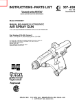
Accessories
Use Only Genuine Graco Parts and Accessories
Four Finger Trigger 183–104
Longer than standard trigger. Reduces trigger pull
when spraying mastics and heavy fluids. Replaces
item 3, in the parts list, page 17.
Plastic Ball Tipped Fluid Needle 220–413
For fluid pressures below 500 psi (35 bar) and light
viscosity fluid. Replaces item 5, in the parts list,
page 17.
Ruby Ball Tipped Fluid Needle 222–497
For use with acid catalyzed finishes. Replaces item 5,
in the parts list, page 17.
Fluid Needle Compression Spring 106–452
For spraying higher solids or heavier viscosity fluids.
Replaces item 24, in the parts list, page 17.
Ultra High Molecular Weight Polyethylene Needle
Packing Kit 221–150
Use to replace needle packings (item 47, in the parts
list, page 17) when spraying urethane fluids. Helps
eliminate isocyanate crystallization in packing area.
Grounding Clamp and Wire 222–011
12 ga, 25 ft (7.6 m) wire
Brush 101–892
For cleaning the gun.
High Pressure Ball Valves, Viton Seals
5000 psi (350 bar) Maximum Working Pressure
Can be used as fluid drain valve.
210–657 1/2 npt(m)
210–658 3/8 npt(m)
210–659 3/8 x 1/4 npt(m)
In-line Fluid Filter 210–500
5000 psi (350 bar) Maximum Working Pressure
100 mesh. Fits onto the gun’s fluid connector. 1/4–18
npsm.
168–517
210–501
Filter
164–075
Bleed-type Master Air Valve
300 psi (21 bar) Maximum Working Pressure
Relieves air trapped in the air line between the pump
air inlet and this valve when closed.
107–141 3/4 npt(m x f) inlet & outlet
107–142 1/2 npt(m x f) inlet & outlet
205–264
Dimensions
Technical Data
Maximum Working Fluid Pressure . . . 950 psi (66 bar)
Maximum Working Air Pressure . . . . . . . 100 psi (7 bar)
Maximum Working Fluid Temperature . 120_ F (49_ C)
Weight (less filter) . . . . . . . . . . . . . . . . . . 1.2 lb (0.55 Kg)
Wetted Parts . . . . . . Stainless Steel, Carbide, Ultra
High Molecular Weight Polyethylene, PTFE,rDelrinr
6.7 in.
(170 mm)
Delrinrris a registered trademark of the DuPont
Company.
6.9 in.
(175 mm)
1/4–18 npsm (R1/4–19)
Compound Thread
307-586 21
Notes
Notes
307-586 23
The Graco Warranty and Disclaimers
WARRANTY
Graco warrants all equipment manufactured by it and bearing its name to be free from defects in material and workmanship on
the date of sale by an authorized Graco distributor to the original purchaser for use. As purchaser’s sole remedy for breach of this
warranty, Graco will, for a period of twelve months from the date of sale, repair or replace any part of the equipment proven
defective. This warranty applies only when the equipment is installed, operated and maintained in accordance with Graco’s
written recommendations.
This warranty does not cover, and Graco shall not be liable for, any malfunction, damage or wear caused by faulty installation,
misapplication, abrasion, corrosion, inadequate or improper maintenance, negligence, accident, tampering, or substitution of
non–Graco component parts. Nor shall Graco be liable for malfunction, damage or wear caused by the incompatibility with Graco
equipment of structures, accessories, equipment or materials not supplied by Graco, or the improper design, manufacture,
installation, operation or maintenance of structures, accessories, equipment or materials not supplied by Graco.
This warranty is conditioned upon the prepaid return of the equipment claimed to be defective to an authorized Graco distributor
for verification of the claim. If the claimed defect is verified, Graco will repair or replace free of charge any defective parts. The
equipment will be returned to the original purchaser transportation prepaid. If inspection of the equipment does not disclose any
defect in material or workmanship, repairs will be made at a reasonable charge, which charges may include the costs of parts,
labor and transportation.
DISCLAIMERS AND LIMITATIONS
The terms of this warranty constitute purchaser’s sole and exclusive remedy and are in lieu of any other warranties (express or
implied), including warranty of merchantability or warranty of fitness for a particular purpose, and of any non–contractual
liabilities, including product liabilities, based on negligence or strict liability. Every form of liability for direct, special or consequential damages or loss is expressly excluded and denied. In no case shall Graco’s liability exceed the amount of the purchase price.
Any action for breach of warranty must be brought within two (2) years of the date of sale.
EQUIPMENT NOT COVERED BY GRACO WARRANTY
Graco makes no warranty, and disclaims all implied warranties of merchantability and fitness for a particular purpose, with
respect to accessories, equipment, materials, or components sold but not manufactured by Graco. These items sold, but not
manufactured by Graco (such as electric motor, switches, hose, etc.) are subject to the warranty, if any, of their manufacturer.
Graco will provide purchaser with reasonable assistance in making any claim for breach of these warranties.
Graco Phone
Number
TO PLACE AN ORDER, contact your Graco distributor, or call this number to identify the distributor closest
to you: 1–800–367–4023 Toll Free
Manual Change
Summary
1. Added “do” and “do not” lubricate notes to Service
section drawing.
2. Added Repair Kit 238–224.
Sales Offices: Atlanta, Chicago, Detroit, Los Angeles
Foreign Offices: Belgium, Canada, England, Korea, Switzerland, France, Germany, Hong Kong, Japan
GRACO INC.
24ą307-586
P.O. BOX 1441 MINNEAPOLIS, MN
55440–1441
PRINTED IN U.S.A. 307–586 October 1992, Revised December 1995