1
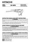
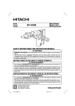
2
1
3
2
5
A
6
1
4
1
3
4
5
6
7
7
8
9
0
8
A
9
10
12
11
C
B
1
D
13
15
14
J
G
E
E
H
F
K
I
16
18
17
M
J
19
J
L
N
20
21
O
K
K
J
22
P
73
7 mm
17 mm
2
Q
English
GENERAL OPERATIONAL PRECAUTIONS
WARNING! When using electric tools, basic safety
precautions should always be followed to reduce the risk
of fire, electric shock and personal injury, including the
following.
Read all these instructions before operating this product
and save these instructions.
For safe operations:
1. Keep work area clean. Cluttered areas and benches
invite injuries.
2. Consider work area environment. Do not expose
power tools to rain. Do not use power tools in
damp or wet locations. Keep work area well lit.
Do not use power tools where there is risk to
cause fire or explosion.
3. Guard against electric shock. Avoid body contact
with earthed or grounded surfaces. (e.g. pipes,
radiators, ranges, refrigerators).
4. Keep children away. Do not let visitors touch the
tool or extension cord. All visitors should be kept
away from work area.
5. Store idle tools. When not in use, tools should
be stored in a dry, high or locked up place, out
of reach of children.
6. Do not force the tool. It will do the job better and
safer at the rate for which it was intended.
7. Use the right tool. Do not force small tools or
attachments to do the job of a heavy duty tool.
Do not use tools for purposes not intended; for
example, do not use circular saw to cut tree
limbs or logs.
8. Dress properly. Do not wear loose clothing or
jewellery, they can be caught in moving parts.
Rubber gloves and non-skid footwear are recommended when working outdoors. Wear protecting
hair covering to contain long hair.
9. Use eye protection. Also use face or dust mask
if the cutting operation is dusty.
10. Connect dust extraction equipment.
If devices are provided for the connection of dust
extraction and collection facilities ensure these are
connected and properly used.
11. Do not abuse the cord. Never carry the tool by
the cord or yank it to disconnect it from the
receptacle. Keep the cord away from heat, oil and
sharp edges.
12. Secure work. Use clamps or a vise to hold the
work. It is safer than using your hand and it frees
both hands to operate tool.
13. Do not overreach. Keep proper footing and balance
at all times.
14. Maintain tools with care. Keep cutting tools sharp
and clean for better and safer performance. Follow
instructions for lubrication and changing accessories. Inspect tool cords periodically and if damaged, have it repaired by authorized service center.
Inspect extension cords periodically and replace,
if damaged. Keep handles dry, clean, and free
from oil and grease.
15. Disconnect tools. When not in use, before servicing, and when changing accessories such as
blades, bits and cutters.
16. Remove adjusting keys and wrenches. Form the
habit of checking to see that keys and adjusting
17.
18.
19.
20.
21.
22.
wrenches are removed from the tool before turning
it on.
Avoid unintentional starting. Do not carry a
plugged-in tool with a finger on the switch. Ensure
switch is off when plugging in.
Use outdoor extension leads. When tool is used
outdoors, use only extension cords intended for
outdoor use.
Stay alert. Watch what you are doing. Use common sense. Do not operate tool when you are tired.
Check damaged parts. Before further use of the
tool, a guard or other part that is damaged should
be carefully checked to determine that it will
operate properly and perform its intended function. Check for alignment of moving parts, free
running of moving parts, breakage of parts,
mounting and any other conditions that may affect
its operation. A guard or other part that is damaged
should be properly repaired or replaced by an
authorized service center unless otherwise
indicated in this handling instructions. Have
defective switches replaced by an authorized
service center. Do not use the tool if the switch
does not turn it on and off.
Warning
The use of any accessory or attachment, other
than those recommended in this handling
instructions, may present a risk of personal injury.
Have your tool repaired by a qualified person.
This electric tool is in accordance with the relevant
safety requirements. Repairs should only be carried
out by qualified persons using original spare parts.
Otherwise this may result in considerable danger
to the user.
PRECAUTIONS ON USING HAMMER DRILL
䡬 Wear earplugs to protect your ears during operation.
䡬 Do not touch the bit during or immediately after
operation. The bit becomes very hot during operation
and could cause serious burns.
䡬 Before starting to break, chip or drill into a wall,
floor or ceiling, thoroughly confirm that such items
as electric cables or conduits are not buried inside.
䡬 Always hold the body handle and side handle of
the power tool firmly. Otherwise the counterforce
produced may result in inaccurate and even
dangerous operation.
4
English
SPECIFICATIONS
Voltage (by areas)*
(110V, 115V, 120V, 127V, 220V, 230V, 240V)
Power input
950 W*
Capacity
Drill bit: 40 mm
Core bit: 105 mm
No load speed
360/min.
Full-load impact rate
2800/min.
Weight (without cord, side handle)
6.5 kg
•Be sure to check the nameplate on product as it is subject to change by areas.
䡬 Large dia. hole boring (Rotation + Striking)
STANDARD ACCESSORIES
(1) Case (Molded plastic) .............................................. 1
(2) Side Handle ............................................................... 1
(3) Stopper ....................................................................... 1
(4) Hexagon Bar Wrench (for 6 mm screw) ............ 1
(5) Hexagon Bar Wrench (for 5 mm screw) ............ 1
(6) Hammer Grease A ................................................... 1
(7) Dust cup ..................................................................... 1
Standard accessories are subject to change without
notice.
OPTIONAL ACCESSORIES (sold separately)
䡬 Through-hole drilling (Rotation + Striking)
(1) Drill bit (hexagon shank)
Overall length: 280, 400, 505 mm
External dia.: 16, 19, 22, 25, 28, 32, 38 mm
䡬 Anchor hole drilling (Rotation + Striking)
Application drill bit
Morse taper
(No. 1)
Drill bit (taper shank)
11, 12, 14.3, 14.5, 17.5 mm
Morse taper
(No. 2)
Drill bit (tape shank)
21.5 mm
B-taper
5
(2) Taper shank
adapter
Taper shank
adapter
A-taper
(Guide
plate)
(2) Core
bit
(3) Core bit
shank
(1) Center pin
䢇 Applied to core bits from 38 mm to 105 mm
䢇 Applied to core bits 32 mm and 35 mm
NOTE
Do not use core bits 25 mm or 29 mm.
(2) Core bit
䢇 External dia. 25, 29, 32, 35, 38, 45, 54, 64, 79, 94,
105 mm
(with guide plate, not applicable to cores 25 mm
or 29 mm)
(3) Core bit shank
䢇 Applied to core bits above 38 mm
䢇 Applied to core bits below 35 mm
䡬 Anchor work (for self-drilling anchors)
(1) Anchor adapter (for Rotation + Striking)
Anchor sizes:
W1/4, W5/16, W3/8, W1/2, W5/8
(No. 20) (No. 25) (No. 30) (No. 40) (No. 50)
(3) Cotter
(1) Drill bit (taper shank)
External dia.: 11, 12, 14.
3, 14.5, 17.
5, 21.5 mm
(1) Center
pin
Taper shank adapter formed Ataper or B-taper is provided as
optional accessory, but drill bit for
it is not provided.
(2) Drift key
䡬 Crushing (Striking)
(1) Bull point
Overall length: 280, 450 mm
䡬 Groove digging and edging (striking)
(1) Cold chisel
Overall length: 280, 450 mm
English
䡬 Asphalt cutting (striking)
(3) Insert the drill bit until it hits the end of the hole,
and make sure that the dust cup is not in contact
with the tool holder. If the dust cup is found to be
in contact with the tool holder, shift it a little forward.
(1) Cutter
䡬 Syringe (for chip removal)
䡬 Hammer grease A
500 g (in a can)
30 g (in a green tube)
Optional accessories are subject to change without
notice.
APPLICATIONS
䡬 Drilling holes in concrete
䡬 Drilling anchor holes
䡬 Crushing concrete, chipping, digging, and squaring
(by applying optional accessories)
PRIOR TO OPERATION
1. Power source
Ensure that the power source to be utilized conforms
to the power requirements specified on the product
nameplate.
2. Power switch
Ensure that the power switch is in the OFF position.
If the plug is connected to a power receptacle while
the power switch is in the ON position, the power
tool will start operating immediately, which could
cause a serious accident.
3. Extension cord
When the work area is removed from the power
source, use an extension cord of sufficient thickness
and rated capacity. The extension cord should be
kept as short as practicable.
4. How to install tool
NOTE
For tools such as a bull point and a cold chisel, use
only Hitachi genuine parts.
(1) Clean, then smear the tool shank with the grease
provided in the green tube (Fig. 1).
(2) The grip can be rotated manually at an 60° angle.
Fully turn the grip in the direction of the arrow A
mark on the grip
as shown in Fig. 2 so that the
mark on the front sleeve.
is aligned with the
(Fig. 2)
(3) Insert the shank of the tool until it makes contact
with the back side of the hole. (Fig. 2)
” so that
(4) Turn the grip in the direction of “Lock
the
mark on the grip is aligned with the
mark on the front sleeve. The tool is locked.
Remove the drill bit in the reverse order. (Fig. 2)
5. Fixing Dust cup
When a worker is engaged in an operation with the
main body faced upward, if a dust cup is fixed to
a drill bit, the inside of a tool holder can be prevented
from any possible invasion of dust. The dust cup
should be fixed as explained below.
(1) Insert the dust cup into the drill bit. (Fig. 3)
(2) Fix the drill bit to the tool holder. (Fig. 4)
HOW TO USE THE HAMMER DRILL
1. How to drill holes (Fig. 5)
(1) Pull the switch trigger after applying the drill bit tip
to the drilling position.
(2) It is unnecessary to forcibly press the hammer drill
main body. It is sufficient to slightly press the
hammer drill to an extent that shavings are freely
discharged.
CAUTION
Although this machine is equipped with a safety
clutch, if the drill bit becomes bound in concrete
or other material, the resultant stoppage of the drill
bit could cause the machine body to turn in reaction.
Ensure that the main handle and side handle are
gripped firmly during operation.
2. How to chip or crush (Fig. 6)
By applying the drill bit tip to the chipping or
crushing position, operate the hammer drill by
utilizing its empty weight.
Forcible pressing or thrusting is unnecessary.
3. Install the stopper (Fig. 7)
(1) Loosen the side handle and insert the straight portion
of the stopper into the handle bolt hole.
(2) Move the stopper to the specified position and rotate
the side handle clockwise to fix the stopper.
4. Warming up (Fig. 8)
The grease lubrication system in this unit may require
warming up in cold regions.
Position the end of the bit so makes contact with
the concrete, turn on the switch and perform the
warming up operation. Make sure that a hitting
sound is produced and then use the unit.
CAUTION
When the warming up operation is performed, hold
the side handle and the main unit securely with both
hands to maintain a secure grip and avoid being
turned around by the drill.
DRILLING AND DRIVING-IN OPERATIONS FOR
ANCHORS
Use the optional accessories for anchors, such as anchor
adapter and taper shank adapter.
1. When a rotation striking anchor adapter is used.
(1) Install the self-drilling anchor in the anchor adapter
(Fig. 9).
(2) Turn ON the switch and drill a base hole with the
self-drilling anchor. (Fig. 10)
At the start of the hole-drilling slightly tilt the hammer
drill to determine the hole position.
(3) After cleaning out dust with a syringe, attach the
plug to the anchor tip and drive in the anchor with
a manual hammer.
(4) After driving in the anchor, use the drift key to
separate the anchor. (Fig. 11)
(5) By employing a manual hammer or pliers, snap off
the tapered portion of the anchor. (Fig. 12)
CAUTION
Since the snapped-off tapered portion will fly out,
pay attention to the snapping direction.
6
English
2. When a taper shank adapter is used. (Fig. 13)
(1) Install drill bit with taper shank in the taper shank
adapter.
(2) Turn the power on and drill a base hole to the depth
sounded by indicating groove on the drill bit.
(3) After cleaning out dust with a syringe, attach the
plug to the anchor tip and drive in the anchor with
a manual hammer.
(4) To remove the drill bit (taper shank), insert the
cotter into the slot of the taper shank adapter and
strike the head of the cotter with a hammer
supporting on a rest. (Fig. 14)
HOW TO HANDLE A CORE BIT
When a core bit is used, large caliber holes and blind
holes can be drilled. In this case, use optional accessories
for core bits (such as a center pin and core bit shank) for
more rational operation.
1. Mounting
CAUTION
Prior to mounting a core bit, always disconnect the
plug from the power supply receptacle.
(1) Mount the core bit on the core bit shank. (Fig. 15)
Before that, feed oil to the screw portion of core
bit shank for easy dismount.
(2) Mount the core bit shank on the drill main body
in the same manner as in mounting the drill bit and
the bull point. (Fig. 16)
(3) Insert the center pin into the guide plate until it
reaches the extremity.
(4) Fit in the guide plate by aligning its concaved
portion with the core bit tip. When the position of
the concave is shifted by turning the guide plate
right or left, the guide plate never slips off even
when the drill is used in a downward direction.
(Fig. 17)
2. Drilling holes
(1) Insert the plug into a power supply receptacle.
(2) A spring is built in the center pin. By straightly and
gently pressing it to the wall or floor surface, the
entire surface of the core bit tip attains contact to
start the hole drilling job. (Fig. 18)
(3) When the hole depth reaches approximately 5 mm,
the hole position can be determined. Then remove
the center pin and guide plate from the core bit and
continue the hole drilling job.
CAUTION
When removing the center pin and guide plate,
always disconnect the plug from the power supply
receptacle.
3. How to dismount the core bit
䡬 By holding the drill (with the core bit inserted) in
an upward position, drive the drill to repeat impact
operation two or three times, whereby the screw
is loosened and the drill becomes ready for
disassembly. (Fig. 19)
䡬 Remove the core bit shank from the drill, hold the
core bit with one hand, and strongly strike the head
of the hexagonal portion of the core bit shank with
a manual hammer two or three times, whereby the
round head screw is loosened and the drill is ready
for disassembly. (Fig. 20)
7
HOW TO REPLACE GREASE
This machine is of full air-tight construction to protect
against dust and to prevent lubricant leakage. Therefore,
the machine can be used without lubrication for long
periods. Replace the grease as described below.
1. Grease replacement period
After purchase, replace grease after every 6 months
of usage. Ask for grease replacement at the nearest
authorized Hitachi Service Agent. Proceed for
replacement of grease.
2. Grease replacement
CAUTION
Before replacing the grease, turn the power off and
pull out the power plug.
(1) Remove the crank case cover and wipe off the
grease inside. (Fig. 21)
(2) Supply 20g of Hitachi Electric Hammer Grease A
(Standard accessory, contained in tube) to the crank
case.
As the tube contain 30g of grease, supply 2/3 of
the contained grease.
(3) After replacing the grease, install the crank case
cover securely.
NOTE
The Hitachi Electric Hammer Grease A is of the low
viscosity type. If necessary purchase from an
authorized Hitachi Service Agent.
MAINTENANCE AND INSPECTION
1. Inspecting the tool
Since use of a dull tool will degrade efficiency and
cause possible motor malfunction, sharpen or replace
the tool as soon as abrasion is noted.
2. Inspecting the mounting screws:
Regularly inspect all mounting screws and ensure
that they are properly tightened. Should any of the
screws be loose, retighten them immediately. Failure
to do so could result in serious hazard.
3. Maintenance of the motor
The motor unit winding is the very “heart” of the
power tool. Exercise due care to ensure the winding
does not become damaged and/or wet with oil or
water.
4. Inspecting the carbon brushes (Fig. 22)
The Motor employs carbon brushes which are
consumable parts. When they become worn to or
near the “wear limit”, it could result in motor trouble.
When an auto-stop carbon brush is equipped, the
motor will stop automatically. At that time, replace
both carbon brushes with new ones which have the
same carbon brush Numbers shown in the figure.
In addition, always keep carbon brushes clean and
ensure that they slide freely within the brush holders.
5. Replacing carbon brushes
Loosen the two set screws and remove the tail
cover. Remove the brush caps and carbon brushes.
After replacing the carbon brushes, tighten the brush
caps securely and install the tail cover with securely
tightening two set screws.
NOTE
Due HITACHI’s continuing program of research and
development, the specifications herein are subject to
change without prior notice.
Español
PRECAUCION ES GENERAL ES PARA
OPERACIÓN
¡ADVERTENCIA! Cuando utilice herramientas eléctricas,
tome las medidas de seguridad básicas para reducir el
riesgo de incendios, descargas eléctricas, y lesiones,
incluyendo lo siguiente. Lea todas todas estas
instrucciones antes de utilizar este producto y guárdelas.
Para realiza roperaciones seguras:
1. Mantener el área de trabajo limpia, áreas y bancos
de trabajo desordenados son causa de da ños
personales.
2. Considerar el medio ambiente del área de trabajo.
No exponer las herramientas eléctricas a la lluvia.
No usar herramientas eléctricas en lugares mojados o húmedos. Mantener el área de trabajo bien
iluminada.
No utilice herramientas eléctricas cuando exista el
riesgo de incendios o de explosión.
3. Protegerse contra descargas eléctricas. Evitar el
contacto del cuerpo con las superficies puestas
a tierra. (p. ej., tubos, radiadores, hornos de
microondas, o refrigeradores.)
4. Mantener a los ni ños alejados. No dejar que los
visitantes toquen las herramientas ni los cables
de extensión. Todos los visitantes deberán
mantenerse alejados del área de trabajo.
5. Guardar las herramientas que no se usen y
ponerlos en lugares secos, altos o cerrados, fuera
del alcance de los ni ños.
6. No forzar las herramientas, éstas trabajarán más
y con mayor seguridad cuando cumplan con las
especificaciones para las cuales fueron diseñadas.
7. Usar las herramientas apropiadas. No forzar
pequeñas herramientas o accesorios a realizar el
trabajo de herramientas de mayor potencia. No
utilizar herramientas para otros propósitos para
los cuales no fueron dise ñadas, por ejemplo, no
utilizar sierras circulares para cortar ramas de
árboles o troncos.
8. Vestir apropiadamente. No ponerse ropas que
queden flojas ni tampoco joyas. Estas podrian
quedar atrapadas en las partes móviles de las
herramientas. Cuando se trabaje en exteriores, se
recomienda el uso de guantes de goma y calzado
que no resbale.
9. Usar gafas de protección. Usar también mascarillas
contra el polvo si las condiciones de corte fuesen
polvorientas.
10. Conecte un equipo colector de polvo.
Si existen dispositivos para la conexión de equipos
de extracción y recolección de polvo, cerciórese
de queéstos estén conectados adecuadamente, y
de utilizarlos en la forma correcta.
11. Cuidar del cable. Nunca lleve las herramientas
colgando del cable, tampoco tire del cable para
efectuar la desconexión de las herramientas.
Mantener el cable alejado del calor, aceite y bordes
agudos.
12. Asegurar la pieza de trabajo usando para ello
abrazaderas o un tornillo. Esto es más seguro que
usar las manos, ademas, ambas manos quedan
libres para operar la herramienta.
13. No extenderse excesivamente para efectuar un
trabajo. Mantener en todo momento un buen
balance y base de apoyo.
14.
15.
16.
17.
18.
19.
20.
21.
22.
Mantener cuidadosamente las herramientas.Tener
las siempre limpias y afiladas para obtener un
mejor rendimiento y un funcionamiento más
seguro. Seguir siempre las instrucciones para la
lubricación y el cambio de accesorios. Inspeccionar
periódicamente los cables de las herramientas y
si estuviesen da nãdos, hacer que los reparen
técnicos ó expertos. Inspeccionar periodicamente
los cables de extensión y cambiarlos si estuviesen
da ñados. Mantener los mangos secos, limpios,
y libres de aceite y grasa.
Desconectar las herramientas cuando no se usen,
antes de repararlas, y cuando se cambien
accesorios como por ejemplo, cuchillas, brocas,
cortadores, etc.
Quitar las cuñas y las llaves de tuercas.
Acostumbrarse a comprobar si se han quitado las
cu ñas y las llaves de tuercas antes de poner las
harramientas en funcionamiento.
Evitar puestas en funcionamiento sin fin alguno.
No llevar las herramientas con los dedos en los
inerruptores mientras que éstas cstán conectadas.
Cuando se conecten las herramientas, cerciorarse
de que los interruptores esten en la posición de
desconectados.
Para usos en exteriores usar cables de extensión.
Cuando las herramientas vayan a ser usadas en
exteriores, usar solamente cables de extensión
diseñados para tal propósito.
Estar siempre alerta y poner atención a lo que se
está haciendo, usar el sentido común y no operar
con la herramienta cuando se esté cansado.
Comprobar las piezas dañadas. Antes de seguir
con el funcionamiento de las herramientas, las
piezas que estén dañadas deberán comprobarse
cuidadosamente para determinar si pueden
funcionar apropiadamente y cumplir con la función
para las que fueron dise ñadas. Comprobar el
alineamiento y agarrotamiento de piezas móviles,
rotura de piezas, montura, y cualiquier otra
anomalia que pudiese afectar al rendimiento de
la herramienta. Cualquier pieza que estuviese da
ñada deberá repararse apropiadamente o
cambiarse en un centro de reparaciones autorizado,
al menos que se indique, lo contrario en este
manual de instrucciones. Procurar que los
interruptores defectuosos los cambie un centro de
reparaciones autorizado.
No usar las herramientas si sus interruptores no
funcionasen apropiadamente.
Advertencia
La utilización de cualquier accesorio o aditivo no
recomendado en este manual de instrucciones
puede conducir al riesgo de lesiones.
En caso de avería, haga que su herramienta sea
reparada por un técnico cualificado.
Esta herramienta eléctrica está de acuerfdo con
los requisitos de seguridad pertinentes. Las
reparaciones solamente deberán realizarlas
técnicos cualificadosutilizando piezas de repuesto
originales. De lo contrario, el usuario podría
lesionarse.
8
Español
PRECAUCIONES AL USAR EL MARTILLO
ROTO-PERCUTOR
䡬 Usar protectores de oídos durante el trabajo.
䡬 No tocar la broca durante ni inmdiatamente después
de trabajar, puesto que se pone ardiente y puede
causar quemaduras serias.
䡬 Antes de empezar a romper, picar o perforar en una
pared, suelo o techo, comprobar cuidadosamente
que no hayan objetos empotrados, tales como cables
o conductos eléctricos.
䡬 Sujetar siempre firmemente al asidero del cuerpo
y el asidero lateral de la harrmienta. De lo contrario,
la contrafuerza producida podría causar un
funcionamiento impreciso e incluso peligroso.
ESPECIFICACIONES
Voltaje (por áreas)*
(110V, 115V, 120V, 127V, 220V, 230V, 240V)
Entrada
950 W*
Capacidad
Barrena: 40 mm
Barrena tubular: 105 mm
Velocidad sin carga
360/min.
Impacto a carga plena
2800/min.
Peso (sin cable ni mango lateral)
6,5 kg
* Verficar indefectiblemente los datos de la placa de características de la máquina, pues varían de acuerdo al país
de destino.
ACCESORIOS ESTANDAR
(1)
(2)
(3)
(4)
Caja (Plástica) ............................................................. 1
Mango lateral ............................................................. 1
Tope ............................................................................. 1
Llave de barra hexagonal ........................................ 1
(para tornillos de 6 mm)
(5) Llave de barra hexagonal ....................................... 1
(para tornillos de 5 mm)
(6) Grasa A para martillo ............................................. 1
(7) Copa para el polvo ................................................... 1
Los accesorios estándar están sujetos a cambios sin
previo aviso.
Adaptador de
espiga cónica
Barrena aplicable
Cono Morse
(N°. 1)
Barrena (espiga cónica)
11 12 14,3 14,5 17,5 mm
Cono Morse
(N°. 2)
Barrena (espiga cónica)
21,5 mm
Cono A
Cono B
Adaptador de espiga cónica
formada por el dispositivo
ahusador A o el B, provisto como
accesorio opcional, pero no se
provee barrena de perforar.
䡬 Perforación de orificio de diámetro grande (Rotación
+ percusión)
ACCESORIOS FACULTATIVOS
(de venta por separado)
䡬 Perforación por orificio (Rotación + percusión)
(Placa guía)
(1) Barrena (espiga hexagonal)
Longitud total: 280 400 505 mm
Diámetro externo: 16 19 22 25 28 32 38 mm
䡬 Perforación de orificio de anclaje (Rotación +
percusión)
(3) Cortadora
(1) Barrena
Diàmetro externo: 11
12 14,3 14,5 17,5
21,5 mm
9
(2) Adaptador
de espiga
cónica
(1) Pasador
contral
(2) Barrena
(3) Espiga de
barrena tubular
(1) Pasador central
䢇 Aplicable a barrenas de 38 mm ~ 105 mm
䢇 Aplicable a barrenas de 32 mm y 35 mm
NOTA
No usar barrenas de 25 y 29 mm
(2) Barrena
䢇 Diámetro externo
25 29 32 35 38 45 54 64 79 94 105 mm
(Con placa guía no aplicable a barrenas de 25 y
29 mm)
(3) Espiga de barrena tubular
䢇 Aplicable a barrenas de más de 38 mm
䢇 Aplicable a barrenas de menos de 35 mm
䡬 Trabajo de anclaje (para anclajes de perforado
propio)
Español
(1) Adaptador de anclaje (para rotación + percusión)
Tamaño de anclaje:
W1/4, W5/16, W3/8, W1/2, W5/8
(N°. 20) (N°. 25) (N°. 30) (N°. 40) (N°. 50)
(2) Cuña sacabarrenas
䡬 Romper (Percusión)
(1) Puntero
Largo total: 280 450 mm
䡬 Excavar, ranurado y rebordes (percusión)
(1) Cortafrio
Largo total: 280 450 mm
䡬 Corte de asfalto (percusión)
(1) Cortadora
䡬 Jeringa (extracción de resíduos)
䡬 Grasa A para martillo
500 g (en una lata)
30 g (en un tubo naranja)
Los accesorios facultativos están sujetos a cambios sin
previo aviso.
APLICACIONES
䡬 Perforación de orificios en concreto
䡬 Perforación de orificios de anclaje
䡬 Romper hormigón, picar, cavar y cuartear (con
accesorios opcionales).
ANTES DE LA PUESTA EN MARCHA
1. Alimentación
Asegurarse de que la alimentacion de red que ha
de ser utilizada responda a las exigencias de corriente
especificadas en la placa de características del
producto.
2. Conmutador de alimentación
Asegurarse de que el conmutador de alimentación
esté en la posición OFF (desconectado). Si la clavija
está conectada en la caja del enchufe mientras el
conmutador de alimentación esté en posición ON
(conectado) las herramientas eléctricas empezarán
a trabajar inmediatamente, provocando un serio
accidente.
3. Cable de prolongación
Cuando está alejada el área de trabajo de la red
de alimentación, usar un cable de prolongación de
un grosor y potencia normal suficiente. El cable de
prolongación debe ser mantenido lo más corto
posible.
4. Montaje de la herramienta
NOTA
Para usar herramientas tales como el puntero y
cortafrío, usar siempre piezas genuinas Hitachi.
(1) Limpiar y engrasar la espiga con la grasa provista
(Fig. 1)
(2) El sujetador podrá girarse manualmente con un
ángulo de 60° en cualquier sentido.
Gire completamente el sujetador en el sentido de
la flecha A como se muestra en la Fig. 2 de forma
del mismo quede alineada con
que la marca
del manguito frontal. (Fig. 2)
la marca
(3) Inserte el vástago de la herramienta hasta que entre
en contacto con la parte posterior del orificio.
(Fig. 2)
(4) Gire el sujetador en el sentido de “Lock
” de
del sujetador quede alineado
forma que la marca
del manguito frontal. La
con la marca
herramienta quedará bloqueada. Quite la broca en
orden inverso. (Fig. 2)
5. Fijación de la copa para el polvo
Cuando el operario trabaje sobre el nivel de los
ojos, si fija una copa para el polvo en la broca, se
impedirá que entre polvo en el interior del
portabrocas. La copa para el polvo deberá fijarse
como se explica a continuación.
(1) Inserte la copa para el polvo en la broca. (Fig. 3)
(2) Fije la broca al protabrocas. (Fig. 4)
(3) Inserte la broca hasta que toque el extremo del
orificio, y cerciórese de que la copa para el polvo
no quede en contacto con el protabrocas. Si la copa
para el polvo está en contacto con el portabrocas,
deslícela un poco hacia adelante.
MODO DE UTILIZACION
1. Taladrar orificios (Fig. 5)
(1) Oprimir el interruptor de operación luego de apoyar
la punta de la barrena en la posición de taladrar.
(2) No es necesario presionar el cuerpo principal del
martillo perforador. Es suficiente con empujar
ligeramente el martillo de taladrar teniendo en cuenta
que los materiales saltan libremente, al taladrar.
PRECAUCION
Aunque este aparato se equipa con un embrague
de seguridad, si se atasca la barrena de taladrar en
el hormigón u otro material semejante, puede pasar
que, al atascarse la barrena, el cuerpo del martillo
gire en dirección opuesta.
Asegurarse entonces de que el mango principal y
el lateral están bien empuñados durante el uso de
esta herramienta.
2. Forma de picar o romper (Fig. 6)
Aplicando la punta de la barrena en posición de
picar o romper, hacer funcionar el martillo perforador
aplicando su propio peso.
No es necesario presionar o empujar excesivamente.
3. Instalar el tope (Fig. 7)
(1) Alfojar el mango lateral e insertar la parte recta del
tope en el orificio del perno de manija.
(2) Aflojar el mango lateral, y mover el tope a la posición
especificada y rotar el mango lateral a la derecha
para fijar el tope.
4. Calentamiento (Fig. 8)
El sistema de lubricación de esta unidad puede
requerir calentamiento en ciertas regiones.
10
Español
Coloque el extremo de la broca de forma que entre
en contacto con el hormigón, ponga en ON el
interruptor de alimentación principal de la unidad,
y realice la operación de calentamiento. Cerciórese
de que se produzca un sonido de martilleo, y después
utilice la unidad.
PRECAUCION
Cuando haya realizado la operación de
calentamiento, sujete con seguridad el mango lateral
y la unidad principal con ambas manos para asegurar
una buena sujeción y evitar que la m†quina le haga
girar.
PERFORACION E INCRUSTACION DE
ANCLAJES
Usar los accesorios opcionales para los anclajes, tales
como adaptador de anclaje y adaptador de espiga cónica.
1. Cuando se use adaptador de anclaje de rotaciónpercusión.
(1) Instalar el anclaje de perforación propia en el
adaptador de anclaje. (Fig. 9)
(2) Poner el interruptor en “ON” y perforar un agujero
base con el anclaje de auto-perforación (Fig. 10)
Al comienzo de la perforación del orificio, inclinar
ligeramente la herramienta para determinar bien la
posición del orificio.
(3) Después de limpiar el polvo con una jeringa, colocar
el tapón en la punta del anclaje y meterlo con un
martillo manual.
(4) Luego de insertar el anclaje, usar la cuña
sacabarrenas para separar el anclaje. (Fig. 11)
(5) Empleando un martillo manual sacar de un glope
la parte cónica del anclaje. (Fig. 12)
PRECAUCION
Debido a que esta parte sobrante saltará al golpearla,
prestar atención a su dirección.
2. Cuando se use un adaptador de espiga cónica
(Fig. 13)
(1) Instalar la barrena en el adaptador de espiga cónica.
(2) Conectar el aparato y perforar un orificio base a una
profundidad correspondiente a la ranura indicadora
del tope en el orificio del perno de manija por la
de la barrena.
(3) Luego, limpiar el polvo con una jeringa, colocar el
tapón en la punta del anclaje e instertar éste con
un martillo manual.
(4) Para quitar la broca (espiga ahusada), insertar la
chaveta en la ranura del adaptador de la espiga
ahusada y golperar la cabeza de la chaveta con un
martillo. Usar apoyos como se muestra en la
Fig. 14.
USO DE BARRENA TUBULAR
Cuando se usa una barrena tubular, pueden perforarse
orificios grandes y orificios ciegos. En este caso, hay que
emplear los accesorios opcionales para barrenas
tubulares (tales como el pasador central y la espiga de
barrena tubular) para trabajar de modo más racional.
1. Montaje
PRECAUCION
Antes de montar una barrena tubular, siempre hay
que desenchufar el aparato del tomacorriente de la
pared.
11
(1) C o l o c a r l a b a r r e n a t u b u l a r e n l a e s p i g a
correspondiente (Fig. 15). Antes de ello, agregar
aceite en la parte de rosca de la barrena tubular
para facilitar el desmontaje.
(2) Colocar la barrena tubular en el cuerpo principal del
taladro del mismo modo que se hizo con la barrena
y el puntero (Fig. 16)
(3) Insertar el pasador central en la placa guía gasta
que alcance la extremidad.
(4) Colocar la placa quía alineando su parte cóncava
con la punta de la barrena tubular.
Cuando la posición de la parte cóncava se cambia,
girando la placa guía a derecha o izquierda, ésta
nunca debe salirse, aún cuando el taladro se use
en dirección hacia abajo (Fig. 17).
2. Perforación
(1) Enchufar el aparato en el tomacorriente de pared.
(2) El pasador central tiene un resorte incluido y,
presionándolo levemente y en forma recta, se pone
en contacto toda la superficie de la punta de la
barrena para comenzar a taladrar. (Fig. 18)
(3) Cuando el orificio alcanza una profundidad de 5 mm
la posición del orificio puede determinarse
perfectamente. Luego, quitar el pasador central y
la placa guía de la barrena tubular y continuar
taladrando.
PRECAUCION
Cuando se quita el pasador central y la placa guía,
siempre hay que desenchufar el aparato del
tomacorriente.
3. Desmontaje de la barrena tubular
䡬 Sosteniendo el taladro (con la barrena tubular puesta)
en posición invertida, accionar el taladro para que
repita la operación de impacto dos o tres veces con
ello, se afloja el tornillo y el taladro queda listo para
desarmarse. (Fig. 19)
䡬 Quitar la espiga de la barrena tubular del taladro,
sosteniendo la barrena tubular con una mano y
golpear con fuerza la cabeza de la parte hexagonal
de la espiga de la barrena tubular, con la mano dos
o tres veces, para aflojar el tornillo de cabeza
redonda, con lo cual, el taladro queda listo para
desarmarse. (Fig. 20)
CAMBIO DE GRASA
Esta máquina es de construcción completamente
cerrada, para evitar que entre polvo y haya fugas de
lubricante. Por ello, la herramienta puede usarse sin
lubricarse por largos periodos.
Cuando so requiere cambiar la grasa, proceder como
sigue:
1. Período de cambio de grasa:
Luego de adquirir la herramienta, cambiarle la grasa
cada 6 meses de uso.
Consultar para ello con el agente de servicio Hitachi
autorizado.
Procedimiento de cambio de grasa.
2. Cambio de grasa
PRECAUCION
Antes de cambiar la grasa, desconectar el aparato
y desenchufarlo del tomacorriente.
(1) Quitar la cubierta del cigüeñal y limpiar la grasa
interna. (Fig. 21)
Español
(2) Aplicar 20g de grasa para martillo eléctrico Hitachi
tipo A (accesorio normales, contenida en tubo) en
el cárter.
Como el tubo contiene 30g de grasa, proveer 2/3
de la grasa contenida.
(3) Luego de cambiar la grasa, instalar la cubierta del
cigüeñal firmemente.
NOTA
La grasa A del martillo eléctrico Hitachi es del tipo
de baja densidad. Si es necesario, siempre adquirir
la grasa a un agente de servicio Hitachi autorizado.
MANTENIMIENTO E INSPECCION
1. Inspección d la herramienta
Ya que la utilización de una herramienta de corte
embotada disminuirá la eficiencia de trabajo y podría
causar desperfectos en el motor, afilar o cambiar
las herramientas de corte tan pronto como se note
abrasión en éstas.
2. Inspeccionar los tornillos de montaje:
Regularmente inspeccionar todos los tornillos de
montaje y asegurarse de que estén apretados
firmemente. Si cualquier tornillo estuviera suelto,
volver a apretarlo inmediatamente. El no hacer esto
provocaría un riesgo serio.
3. Mantenimiento de motor:
La unidad de bobinado del motor es el verdadero
“corazón” de las herramientas eléctricas. Prestar el
mayor cuidado y asegurarse de que el bobinado no
se dañe y/o se humedezca con aceite o agua.
4. Inspeccionar los carbones de contacto (Fig. 22)
El motor emplea escobillas de carbón que son partes
consumibles. Cuando se gastan o están cerca del
“limite de desgaste” pueden causar problemas al
motor.
Al equiparse la escobilla de carbón de parada
automática, el motor se detendrá automáticamente
en ese momento hay que proceder a cambiar ambas
escobillas de carbón por la nuevas, que tienen los
mismos números de escobillas de carbón como se
muestra en la figura. Además siempre hay hay que
mantener las escobillas de carbón limpias y
asegurarse de que se muevan libremente en sus
porta-escobillas.
5. Cambio de escobillas de carbón
Quitar la cubierta de cola y luego aflojar el tornillo
de fijación.
Aflojando la tapa de escobilla, pueden quitarse las
escobillas de carbón, al colocar las escobillas, apretar
firmemente la tapa de escobillas y recolocar la
cubierta de con dos tornillos.
OBSERVACION
Debido al programa continuo de investigación y desarollo
de HITACHI estas especificaciones están sujetas a cambio
sin preaviso.
12
18
The exploded assembly drawing should be used only for authorized service center.
Item
No.
1
2
3
4
5
6
7
8
9
10
11
12
13
14
15
16
17
18
19
20
21
23
24
25
26
27A
28
29
30
31
32
33
35
36
37
38
39
40
41
42
43
44
45
46
47
48
49
50A
51
52
53
54
55
56
Part Name
C-Type Spring
Steel Ball
Front Cap
Retaining Ring
Front Washer (A)
Damper Ring
Front Washer (B)
Grip
Saddle Key
Saddle Key Holder
Retaining Ring For D38 Shaft
Rubber Ring
Nylock High Tension Bolt
Front Sleeve
Front Cover
O-Ring (1AS-60)
O-Ring (C)
Second Hammer
Damper Washer
Damper
Washer
Feather Key
Oil Seal (A)
Ball Bearing (6002DDUCMP2S)
Washer
Washer (A)
Gear Holder
Spring (C)
Needle Pin
Second Gear
Spacer
Ball Bearing (629VVMC2EPS2L)
Nylock Bolt (W/Flange)
Distance Piece (B)
Crank Case Cover Ass’y
Rubber Seal
Crank Case
Retaining Ring For D12 Shaft
Crank Shaft
Feather Key
Ball Bearing (6204VVCMPS2S)
Oil Seal (B)
Bearing Cover
Nylock Hex. Socket Hd. Bolt
Needle Bearing (M661)
First Gear
Seal Packing
Gear Cover Ass’y
Feather Key
Sylinder
Valve Band
Striker
O-Ring
Piston
D7.0
D32
M7×25
3×3×8
D6×6
M5×16
3×3×10
M5×16
3×3×20
Item
No.
57
58
59
60
61
62
63
65
66
67
68
69
70
71
72
73
74
75
76
77
78A
79
80
81
82
83
84
85
86
87
88
89
90
91
92
93
94
95
96
97
98
99
100
101
102
103
104
105
106
501
502
503
504
505
Part Name
Piston Pin
Connecting Rod Ass’y
Needle Bearing (NSK AJ50 1203)
Nylock Bolt (W/Flange)
M6×25
Cylinder Case
O-Ring (1AS-60)
Needle Bearing (B) (NTN HMK4520)
Side Handle
Handle Holder
Handle Bolt
Stopper Rod
Ball Bearing (6202VVCMPS2S)
Dust Washer
O-Ring
Hex. Hd. Tapping Screw
D5×55
Dust Washer (A)
Ball Bearing (629VVMC2EPS2L)
Housing
HITACHI Label
Brush Cap
Carbon Brush (Auto Stop Type)
Brush Holder
Nylock Bolt (W/Flange)
M5×25
Hex. Socket Set Screw
M5×8
Bearing Holder
Tail Cover
Tapping Screw (W/Flange)
D5×20
Fan
Armature Ass’y
Stator Ass’y
Brush Terminal
Handle
Switch (C)
Handle Cover
Tapping Screw (W/Flange)
D4×20
Terminal
Cord Clip
Tapping Screw (W/Flange)
D4×16
Cord
Tapping Screw (W/Flange)
D5×25
Name Plate
Cord Armor
Plug (A)
Plug (B)
Connector (50092)
Pillar Terminal
Bearing Washer (C)
Bevel Gear Pinion Set
Bevel Gear Clutch Ass’y
Case
Grease (A)
Hex. Bar Wrench
4MM
Hex. Bar Wrench
5MM
Dust Cup
Parts are subject to possible modification without
notice due to improvements.
20
901
Code No. C99075332 N
Printed in Japan