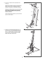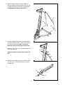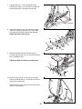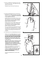
1
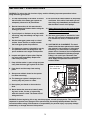
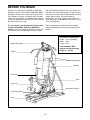
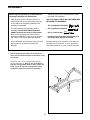
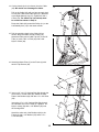
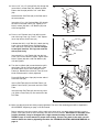
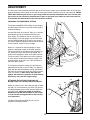
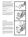
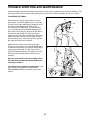
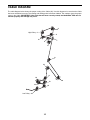
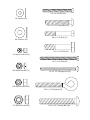
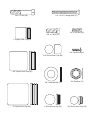
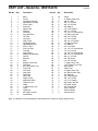
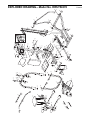
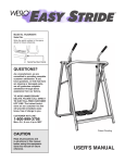
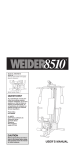
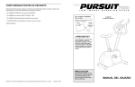
¨
Model No. HRSY54370
Serial No.
(Write the serial number in the space
above for reference.)
Serial Number Decal
QUESTIONS?
As a manufacturer, we are committed to providing complete
customer satisfaction. If you have
questions, or find there are missing or damaged parts, we will
guarantee you complete satisfaction through direct assistance
from our factory.
TO AVOID UNNECESSARY
DELAYS, PLEASE CALL DIRECT
TO OUR TOLL-FREE CUSTOMER
HOT LINE. The trained technicians on our customer hot line
will provide immediate assistance, free of charge to you.
CUSTOMER HOT LINE:
1-800-999-3756
Mon.ÐFri., 6 a.m.Ð6 p.m. MST
Patent Pending
CAUTION
Read all precautions and instructions in this manual before using
this equipment. Save this manual
for future reference.
USER'S MANUAL
TABLE OF CONTENTS
LIMITED WARRANTY . . . . . . . . . . . . . . . . . . . . . . . . . . . . . . . . . . . . . . . . . . . . . . . . . . . . . . . . . . . . . . . . . . .2
IMPORTANT PRECAUTIONS . . . . . . . . . . . . . . . . . . . . . . . . . . . . . . . . . . . . . . . . . . . . . . . . . . . . . . . . . . . . .3
BEFORE YOU BEGIN . . . . . . . . . . . . . . . . . . . . . . . . . . . . . . . . . . . . . . . . . . . . . . . . . . . . . . . . . . . . . . . . . . .4
ASSEMBLY . . . . . . . . . . . . . . . . . . . . . . . . . . . . . . . . . . . . . . . . . . . . . . . . . . . . . . . . . . . . . . . . . . . . . . . . . . .5
ADJUSTMENT . . . . . . . . . . . . . . . . . . . . . . . . . . . . . . . . . . . . . . . . . . . . . . . . . . . . . . . . . . . . . . . . . . . . . . . .12
TROUBLE-SHOOTING AND MAINTENANCE . . . . . . . . . . . . . . . . . . . . . . . . . . . . . . . . . . . . . . . . . . . . . . . .14
CABLE DIAGRAMS . . . . . . . . . . . . . . . . . . . . . . . . . . . . . . . . . . . . . . . . . . . . . . . . . . . . . . . . . . . . . . . . . . . .15
ORDERING REPLACEMENT PARTS . . . . . . . . . . . . . . . . . . . . . . . . . . . . . . . . . . . . . . . . . . . . . . . .Back Cover
Note: An EXPLODED DRAWING/PART LIST and a PART IDENTIFICATION CHART are attached to the center
of this manual. Remove the EXPLODED DRAWING/PART LIST and the PART IDENTIFICATION CHART before
beginning assembly.
HealthRider is a registered trademark of HealthRider Corp., a subsidiary of ICON Health & Fitness, Inc.
LIMITED WARRANTY
ICON Health & Fitness, Inc. (ICON), warrants this product to be free from defects in workmanship and
material, under normal use and service conditions, for a period of ninety (90) days from the date of purchase. This warranty extends only to the original purchaser. ICON's obligation under this warranty is limited to replacing or repairing, at ICON's option, the product through one of its authorized service centers.
All repairs for which warranty claims are made must be pre-authorized by ICON. This warranty does not
extend to any product or damage to a product caused by or attributable to freight damage, abuse, misuse, improper or abnormal usage or repairs not provided by an ICON authorized service center, products
used for commercial or rental purposes, or products used as store display models. No other warranty
beyond that specifically set forth above is authorized by ICON.
ICON is not responsible or liable for indirect, special or consequential damages arising out of or in connection with the use or performance of the product or damages with respect to any economic loss, loss
of property, loss of revenues or profits, loss of enjoyment or use, costs of removal, installation or other
consequential damages of whatsoever nature. Some states do not allow the exclusion or limitation of incidental or consequential damages. Accordingly, the above limitation may not apply to you.
The warranty extended hereunder is in lieu of any and all other warranties and any implied warranties of
merchantability or fitness for a particular purpose is limited in its scope and duration to the terms set forth
herein. Some states do not allow limitations on how long an implied warranty lasts. Accordingly, the above
limitation may not apply to you.
This warranty gives you specific legal rights. You may also have other rights which vary from state to state.
ICON HEALTH & FITNESS, INC., 1500 S. 1000 W., LOGAN, UT 84321-9813
2
IMPORTANT PRECAUTIONS
WARNING: To reduce the risk of serious injury, read the following important precautions before
using the home gym system.
1. It is the responsibility of the owner to ensure
that all users of the home gym system are
adequately informed of all precautions.
13. Be sure that the cable remains on the pulleys
at all times. If the cable binds while you are
exercising, stop immediately and make sure
that the cable is on all of the pulleys.
2. Read all instructions in this manual and in
the accompanying literature before using the
home gym system.
14. Always disconnect the lat bar from the home
gym system when performing an exercise
that does not use the lat bar.
3. If you feel pain or dizziness at any time while
exercising, stop immediately and begin cooling down.
15. The home gym system is intended for home
use only. Do not use the home gym system
in a commercial, rental, or institutional setting.
4. Use the home gym system only on a level
surface. Cover the floor or carpet beneath
the home gym system for protection.
16. CAUTION DECAL PLACEMENT: The decal
shown below has been placed on the home
gym system in two locations. If either decal
is missing, or if either decal is not legible,
please call our Customer Service Department
toll-free at 1-800-999-3756, Monday through
Friday, 6 a.m. until 6 p.m. Mountain Time
(excluding holidays), to order a replacement
decal. Apply the replacement decal to the
location shown.
5. The home gym system is intended for use by
one person at a time and designed to support a maximum user weight of 250 pounds.
6. Inspect and tighten all parts often. Replace
any worn parts immediately. Replace the
cable every two years.
7. Keep children under 12 years of age and pets
away from the home gym system at all times.
Decal is shown at
75% actual size
8. Keep hands and feet away from moving
parts.
9. Always wear athletic shoes for foot protection when exercising.
10. The home gym system is designed to be
used by only one person at a time.
11. Never place your hands or feet under the
deck.
12. Never release the press arm, butterfly arms,
leg lever, lat bar, row bar, or nylon strap
while the frame is raised. The frame will fall
with great force.
WARNING: Before beginning this or any exercise program, consult your physician. This is especially
important for persons over the age of 35 or persons with pre-existing health problems. Read all
instructions before using. ICON assumes no responsibility for personal injury or property damage
sustained by or through the use of this product.
3
BEFORE YOU BEGIN
Thank you for selecting the HealthRider¨ BRS Body
Resistance System. The versatile HealthRider¨ BRS is
designed to develop every major muscle group of the
body. Whether your goal is a shapely figure, dramatic
muscle size and strength, or a healthier cardiovascular
system, the HealthRider¨ BRS will help you to achieve
the specific results you want.
999-3756, Monday through Friday, 6 a.m. until 6 p.m.
Mountain Time (excluding holidays). To help us assist
you, please note the product model number and serial
number before calling. The model number is
HRSY54370. The serial number can be found on a
decal attached to the HealthRider¨ BRS (see the front
cover of this manual).
For your benefit, read this manual carefully before
using the HealthRider¨ BRS Body Resistance
System. If you have additional questions, please call
our Customer Service Department toll-free at 1-800-
Before reading further, please review the drawing
below and familiarize yourself with the parts that are
labeled.
ASSEMBLED DIMENSIONS:
Height: 90 in. (Extended)
Width: 48 in.
Length: 59 in.
High Pulley Station
The HealthRider¨ BRS
requires a minimum ceiling
height of 7 1/2 feet.
Lat Bar
Butterfly Arms
Backrest
Press Arm
Seat
Leg Lever
Resistance Selector
Low Pulley Station
Deck
4
ASSEMBLY
Before beginning assembly, carefully read the
following information and instructions:
¥ Tighten all parts as you assemble them, unless
instructed to do otherwise.
¥ Place all parts of the home gym system in a
cleared area and remove the packing materials;
do not dispose of the packing materials until
assembly is completed.
THE FOLLOWING TOOLS (NOT INCLUDED) ARE
REQUIRED FOR ASSEMBLY:
¥ For help identifying the small parts used in
assembly, use the PART IDENTIFICATION
CHART located in the center of this manual.
Note: Some small parts may have been preattached for shipping. If a part is not in the parts
bag, check to see if it has been pre-attached.
¥ One (1) phillips screwdriver
¥ As you assemble the home gym system, be sure
that all parts are oriented as shown in the
drawings.
Assembly will be more convenient if you have the
following tools: A socket set, a set of open-end or
closed-end wrenches, or a set of ratchet wrenches.
¥ Two (2) adjustable wrenches
¥ One (1) rubber mallet
¥ Lubricant, such as grease or petroleum jelly,
and soapy water will also be needed.
1. Before beginning assembly, be sure that you
have read and understand the information in the
box above.
1
Insert four 3/8Ó x 2 1/2Ó Carriage Bolts (60) up
through the Base (1). Note: It may be helpful to
tape the Carriage Bolt heads in place under the
Base. If you do tape the Carriage Bolt heads,
remove the tape once you finish assembly.
1
60
60
5
2. Press four 2Ó Square Inner Caps (68) into the
Frame (2).
2
68
Identify the Left Wheel Channel (3) and the Right
Wheel Channel (4) by comparing the welded
brackets on the bottom of each Wheel Channel.
68
2
Slide the Left Wheel Channel (3) onto the indicated
Small Wheels (40) attached to the Frame (2).
Note: This will be easier to do if you lie the
Frame on the floor.
4
Slide the Right Wheel Channel (4) onto the Frame
(2) in the same manner.
40
3
68
40
68
3. Slide the Left and Right Wheel Channels (3, 4)
onto the 3/8Ó x 2 1/2Ó Carriage Bolts (60) in the
Base (1). Partially tighten a 3/8Ó Nylon Locknut
(39) onto each Carriage Bolt but do not fully
tighten the Nylon Locknuts yet.
3
4
3
39
39
60
60
1
6
4. Slide the Support Tube (32) onto the Base (1).
Attach the Support Tube to the Base with two 3/8Ó
x 2Ó Bolts (43) and two 3/8Ó Nylon Locknuts (39).
Do not tighten the Nylon Locknuts yet.
4
32
39
39
43
43
1
5. Attach the Support Tube (32) to the Right Wheel
Channel (4) with two 3/8Ó x 1Ó Bolts (16) and two
3/8Ó Nylon Locknuts (39). Note: You need to
attach the lower Bolt and Nylon Locknut first.
5
Attach the Tube (32) to the Left Wheel Channel (3)
in the same manner.
39
16
Tighten the Nylon Locknuts used in steps 3Ð5
now.
39
16
4
32
3
6. Attach the Large Wheel (19) to the Inner Lift Tube
(17) with 1/2Ó x 2 1/2Ó Bolt (52) and a 1/2Ó Nylon
Jam Nut (50).
6
17
50
52
19
7
7. Lubricate the 1/2Ó x 3 1/2Ó Carriage Bolt (49).
Attach the Lift Tube (11) to the Frame (2) with the
Carriage Bolt and a 1/2Ó Nylon Jam Nut (50).
7
11
50
49ÑLubricate
2
8. Attach the Platform Cover (34) and the Crossbar
(18) to the Frame (2) with two 3/8Ó x 2 3/4Ó Bolts
(45) and two 3/8Ó Nylon Locknuts (39). Do not
tighten the Nylon Locknuts yet.
8
39
68
2
34
39
18
68
45
9. Attach the Platform (8) to the Frame (2) and
Crossbar (18) with four 1/4Ó x 2 3/4Ó Bolts (63) and
four 1/4Ó Washers (55).
9
8
Tighten the Nylon Locknuts from step 8 now.
2
55
63
55
18
63
10. Attach a Press Arm (6) to one side of the Press
Frame (5) with two 3/8Ó x 2 1/2Ó Bolts (51) and two
3/8Ó Nylon Locknuts (39).
10
Attach the other Press Arm (6) to the Press Frame
(5) in the same manner.
6
39
6
51
8
5
11. Press a 1Ó Round Inner Cap (36) into one of the
Press Arms (6). Press a 1 3/4Ó Square Inner Cap
(65) into the Press Arm.
11
65
36
65
Repeat this step for the other Press Arm (6).
6
36
6
12. Identify the Right Butterfly Arm (15) and the Left
Butterfly Arm (14). Note the position of the welded
bracket on each Arm. Butterfly Arm identification
is very important for step 13.
12
39
65
Attach a Pulley (41) and a Cable Trap (67) to the
Right Butterfly Arm (15) with a 3/8Ó x 2Ó Bolt (43)
and a 3/8Ó Nylon Locknut (39) but do not fully
tighten the Nylon Locknuts yet.
15
Attach a Pulley (41) and a Cable Trap (67) to the
Left Butterfly Arm (14) with a 3/8Ó x 2Ó Bolt (43)
and a 3/8Ó Nylon Locknut (39) but do not fully
tighten the Nylon Locknuts yet.
41
67
43
24
Press 1 3/4Ó Square Inner Caps (65) into the ends
of the Right and Left Butterfly Arms (15, 14). Wet
the lower end of each Arm with soapy water. Slide
a Butterfly Foam Pad (23) onto the lower end of
each Arm.
14
65
24
65
13. Lubricate the axle on the Right Butterfly Arm (15) .
13
69
Slide the axle on the Right Butterfly Arm (15) into
the Frame (2). Note: Be careful not to confuse
the Right Butterfly Arm with the Left Butterfly
Arm (14); refer to step 12 to identify the Right
Butterfly Arm. Be sure that the upper end of
the Right Arm is behind the indicated bracket
on the Frame (2).
70
71
70
Bracket
71
15
2
IMPORTANT NOTE: Before assembling the 3/4Ó
Retainers (70) be sure that you thoroughly
understand the step. The Retainers can be
assembled only once. If they must be removed,
you will need to order new Retainers.
Lubricate
Axles
14
69
Slide a 3/4Ó Large Washer (71) onto the axle on
the Right Butterfly Arm (15). Tap two 3/4Ó
Retainers (70) and a 3/4Ó Round Cover Cap (69)
onto the axle. Be sure that the teeth on the
Retainers bend toward the Cover Cap, as
shown in the inset drawing.
70
71
Axle
Attach the Left Butterfly Arm (14) in the same
manner.
9
14. Cut the plastic zip tie (not shown) from the Cable
(35). Be careful not to damage the Cable.
14
35
Pull on the Cable (35) until you have enough slack
to route the Cable around the Pulley (41) attached
to the Right Butterfly Arm (15). Tighten the 3/8Ó x
2Ó Bolt (43). The Cable Trap (not shown) must
be oriented as shown in step 12.
15
43 41
14
Route the Cable (35) around the Pulley (41) on the
Left Butterfly Arm (14) in the same manner.
15. Pull the remaining slack in the Cable (35) as
shown. Wrap the Cable around a Pulley (41).
Attach the Pulley and a Cable Trap (67) to the Lift
Tube (11) with a 3/8Ó x 2Ó Bolt (43) and a 3/8Ó
Nylon Locknut (39).
15
35
39
41
43
67
11
16. Attach the Name Plate (7) to the Frame (2) with
two 3/4Ó Tap Screws (62).
16
7
2
62
17. Insert a 1/4Ó x 3 1/2Ó Carriage Bolt (59) through the
center hole in a Seat Plate (29). Attach the Seat
Plate to the Backrest (22) with two 1/4Ó x 3/4Ó Bolts
(56).
17
55
58
Insert the 1/4Ó x 3 1/2Ó Carriage Bolt (59) through
the indicated hole in the Frame (2). Tighten a 1/4Ó
Nylon Locknut (54) with a 1/4Ó Washer (55) onto
the Carriage Bolt.
22
55
29 56
Attach the other end of the Backrest (22) to the
Frame (2) with a 1/4Ó Washer (55) and a 1/4Ó x
3.1/2Ó Bolt (58).
59
10
54
18. Insert a 1/4Ó x 2 1/2Ó Carriage Bolt (57) through the
center hole in a Seat Plate (29). Attach the Seat
Plate to the Seat (23) with two 1/4Ó x 3/4Ó Bolts
(56).
18
23
57
Attach another Seat Plate (29) to the Seat (23) in
the same manner.
57
29
29
Insert the 1/4Ó x 2 1/2Ó Carriage Bolts (57) through
the holes in the Seat Frame (13). Tighten a 1/4Ó
Nylon Locknut (54) with a 1/4Ó Washer (55) onto
each Carriage Bolt.
56
56
13
55
54
19. Press a 1 3/4Ó Square Inner Cap (65) into each
end of the Leg Lever (12). Press a 1 3/4Ó Square
Inner Cap into the Seat Frame (13)
19
65
Lubricate the 3/8Ó x 2 1/2Ó Bolt (51). Attach the Leg
Lever (12) to the Seat Frame (13) with the Bolt
and a 3/8Ó Nylon Jam Nut (74). Do not overtighten the Nylon Jam Nut. The Leg Lever must be
able to pivot freely.
13
74
51ÑLubricate
12
Insert the 3/8Ó x 2 1/2Ó Eyebolt (53) into the Leg
Lever (12) from the direction shown. Tighten a 3/8Ó
Nylon Locknut (39) with a 3/8Ó Flat Washer (46)
onto the Eyebolt.
53
39
46
65
20. Turn the Lock Knob (28) counterclockwise until it
turns freely. Pull the Lock Knob and hold it. Rest
the Seat Frame (13) on one of the pins in the
Frame (2). Release the Lock Knob. Turn the Lock
Knob clockwise until it is firmly tightened.
20
2
13
28
Press 3/4Ó Round Inner Caps (26) into the ends of
each Pad Tube (25).
27
26
Insert a Pad Tube (25) into the Seat Frame (13).
Slide a Foam Pad (27) onto each end of the Pad
Tube.
25
26
12
27
Insert the other Pad Tube (25) into the Leg Lever
(12). Slide a Foam Pad (27) onto each end of the
Pad Tube.
21. Make sure that all parts have been properly tightened. The use of the remaining parts will be explained in
ADJUSTMENT, beginning on page 12 of this manual.
Before using the home gym system, pull the cable a few times to be sure that it moves smoothly over the
pulleys. If the cable does not move smoothly, find and correct the problem. IMPORTANT: If the cable is not
properly installed, it may be damaged when a high resistance setting is used. See the CABLE DIAGRAM on page 15 of this manual for proper cable routing. If there is any slack in the cable, you will
need to remove the slack by tightening the cable. See TROUBLE-SHOOTING AND MAINTENANCE on
page 14.
11
ADJUSTMENT
The instructions below describe how each part of the home gym system can be adjusted. Refer to the exercise
guide accompanying this manual to see how the home gym system should be set up for each exercise. IMPORTANT: When attaching the lat bar or nylon strap, make sure that the attachments are in the correct starting position for the exercise to be performed. If there is any slack in the cables or chain as an exercise
is performed, the effectiveness of the exercise will be reduced.
CHANGING THE RESISTANCE SETTING
The unique HealthRider¨ BRS utilizes its own weight
and the weight of the user to provide a wide range of
resistance settings.
Use the Dial Knob (9) on the Lift Tube (11) to find the
approximate amount of resistance based on your
body weight. The window on the far end of the Lift
Tube displays your body weight. Turn the Dial Knob
until the weight displayed is closest to your weight. If
you will be using the low pulley station and will not be
on the machine, select Ò0Ó as your weight.
9
When Ò0Ó is selected as the body weight, a single
number is displayed in each of the other windows.
This is the pounds of resistance at the low pulley station. When you select any other body weight, two
numbers are displayed in each of the other windows.
The first number, in the white area, is the resistance
at every station except the bench press station. The
second number, in the red area, is the resistance at
the bench press station.
11
33
Body Weight
Window
Resistance
Windows
To change the resistance setting, first pull back the
Adjustment Knob (33) on the Lift Tube (11). Align the
Knob with the desired resistance setting and release
the Knob. Be sure that the Knob fully locks into place
when you release it. Note: Due to the cable and
pulleys, the amount of resistance at each exercise
station may vary from the weight setting.
35
ATTACHING THE LAT BAR, ROW BAR, OR
NYLON STRAP TO THE HIGH PULLEY STATION
38
31
Attach the Lat Bar (21) to the Cable (35) with a Cable
Clip (38). For some exercises, the Chain (37) should
be attached between the Lat Bar and the Cable with
two Cable Clips. Adjust the length of the Chain
between the Lat Bar and the Cable so the Lat Bar
is in the correct starting position for the exercise
to be performed.
37
21
The Nylon Strap (66) and Row Bar (31) can be
attached in the same manner.
12
66
ATTACHING THE LAT BAR, ROW BAR, OR NYLON
STRAP TO THE LOW PULLEY STATION
35
Attach the Lat Bar (21) to the Cable (35) with a Cable
Clip (38). For some exercises, the Chain (37) should
be attached between the Lat Bar and the Cable with
two Cable Clips. Adjust the length of the Chain
between the Lat Bar and the Cable so the Lat Bar
is in the correct starting position for the exercise
to be performed.
38
31
37
21
The Nylon Strap (66) and Row Bar (31) can be
attached in the same manner.
66
ATTACHING THE LEG LEVER TO THE LOW
PULLEY STATION
To use the Leg Lever (12), the seat must be attached
to the front upright (see SEAT ADJUSTMENT below).
Attach the Cable (35) with a Cable Clip (38) to the
Eyebolt (53). Always remove the Cable (35) from
the Eyebolt (53) before removing the seat.
53
38 35
12
SEAT ADJUSTMENT
The Seat Frame (13) can be set at three different
heights. To move the Seat Frame, turn the Lock Knob
(28) counterclockwise until it turns freely. Pull the
Lock Knob and hold it. Lift the Seat Frame and move
it to on one of the other pins in the Frame (2). Be sure
the Seat Frame is securely on the pins. Release the
Lock Knob. Turn the Lock Knob clockwise until it is
firmly tightened.
2
13
28
For some exercises the Seat Frame (13) must be
removed. Turn the Lock Knob (28) counterclockwise
until it turns freely. Pull the Lock Knob and hold it. Lift
the Seat Frame (36) and set it aside. Always disconnect the Cable (35) before removing the Seat
Frame.
35
To reattach the Seat Frame (13), turn the Lock Knob
(28) counterclockwise until it turns freely. Pull the
Lock Knob and hold it. Rest the Seat Frame (36) on
one of the pins in the Frame (2). Release the Lock
Knob. Turn the Lock Knob clockwise until it is firmly
tightened.
13
TROUBLE-SHOOTING AND MAINTENANCE
Inspect and tighten all parts each time you use the home gym system. Replace any worn parts immediately. The
home gym system can be cleaned using a damp cloth and mild non-abrasive detergent. Do not use solvents.
TIGHTENING THE CABLE
1
39
Woven cable, the type of cable used on the home
gym system, can stretch slightly when it is first used.
If there is slack in the cables before resistance is felt,
the cables should be tightened. Slack can be
removed from the Cable (35) by moving the Pulley
(41) to the next hole in the indicated bracket on the
upper end of the Frame (2). Remove the 3/8Ó Nylon
Locknut (39) and the 3/8Ó x 2Ó Bolt (43) from the
Cable Trap (67) and Pulley. Re-attach the Pulley and
Cable Trap to the next hole in the bracket. Be sure
that the Cable Trap is in the proper position and that
the Cable and Pulley move smoothly.
35
2
41
43
67
Additional slack can be removed by moving the
Pulley (41) to the upper hole in the indicated bracket
on the back of the Frame (2). Remove the 3/8Ó Nylon
Locknut (39) and the 3/8Ó x 2Ó Bolt (43) from the
Pulley. Re-attach the Pulley to the upper hole in the
bracket. Be sure that the Cable and Pulley move
smoothly.
2
39
Note: If a cable tends to slip off the pulleys often,
the cable may have become twisted. Remove the
cable and re-install it.
41
35
2
The cable must be replaced every two years. If the
cable needs to be replaced, see ORDERING
REPLACEMENT PARTS on the back cover of this
manual.
43
14
CABLE DIAGRAM
The cable diagram below shows the proper routing of the Cable (35). Use this diagram to be sure that the Cable
has been assembled correctly. The starting and ending points have been labeled. The numbers show the proper
route for the Cable. IMPORTANT: If the Cable has not been correctly routed, the HealthRider¨ BRS will not
function properly and damage may occur.
2
High PulleyÑ1
3
4
7
5
6
8
10
11
14
13
12
15
Low PulleyÑ16
15
9
1/4" x 2 3/4" Bolt (63)
1/4" Washer (55)
3/8" x 2 1/2" Carriage Bolt (60)
3/8" x 2 1/2" Bolt (51)
3/8" Washer (46)
1/2" x 2 1/2" Bolt (52)
1/4" Nylon Locknut (54)
1/4" x 3 1/2" Bolt (58)
3/8" Nylon Jam Nut (74)
1/4" x 3 1/2" Carriage Bolt (59)
3/8" Nylon Locknut (39)
3/8" x 2 1/2" Eyebolt (53)
1/2" Nylon Jam Nut (50)
1/2" x 3 1/2" Carriage Bolt (49)
3/8" x 2" Bolt (43)
1/4" x 2 1/2" Carriage Bolt (57)
1/4" x 3/4" Bolt (56)
3/8" x 1" Bolt (16)
1" Square Inner Cap (64)
3/4" Tap Screw (62)
3/4" Round Outer Cap (69)
1 3/4" Square Inner Cap (65)
3/4" Large Washer (71)
2" Square Inner Cap (68)
1" Round Inner Cap (36)
3/4" Retainer (70)
3/4" Round Inner Cap (26)
PART LISTÑModel No. HRSY54370
Key No.
Qty.
1
2
3
4
5
6
7
8
9
10
11
12
13
14
15
16
17
18
19
20
21
22
23
24
25
26
27
28
29
30
31
32
33
34
35
36
37
38
39
40
1
1
1
1
1
2
1
1
2
1
1
1
1
1
1
4
1
1
1
2
1
1
1
2
2
4
4
1
3
6
1
1
1
1
1
2
1
3
30
4
Description
Base
Frame
Left Wheel Channel
Right Wheel Channel
Press Frame
Press Arm
Name Plate
Platform
Dial Knob
Inner Dial Tube
Lift Tube
Leg Lever
Seat Frame
Left Butterfly Arm
Right Butterfly Arm
3/8Ó x 1Ó Bolt
Inner Lift Tube
Crossbar
Large Wheel
Butterfly Arm Bushing
Lat Bar
Backrest
Seat
Butterfly Foam Pad
Pad Tube
3/4Ó Round Inner Cap
Foam Pad
Lock Knob
Seat Plate
Hand Grip
Row Tube
Support Tube
Adjustment Knob
Platform Cover
Cable
1Ó Round Inner Cap
Chain
Cable Clip
3/8Ó Nylon Locknut
Small Wheel
R1197A
Key No.
Qty.
41
42
43
44
45
46
47
48
49
50
51
52
53
54
55
56
57
58
59
60
61
62
63
64
65
66
67
68
69
70
71
72
73
74
75
76
#
#
#
16
4
8
1
6
9
8
3
1
2
5
1
1
3
8
6
2
1
1
4
2
2
4
1
9
1
6
6
2
4
2
2
4
4
1
4
1
1
2
Description
Pulley
2Ó Square Outer Cap
3/8ÓÕ x 2Ó Bolt
3/8Ó x 1 3/4Ó Bolt
3/8Ó x 2 3/4Ó Bolt
3/8Ó Washer
1/2Ó x 5/8Ó Spacer
3/8Ó x 7 1/4Ó Bolt
1/2Ó x 3 1/2Ó Carriage Bolt
1/2Ó Nylon Jam Nut
3/8Ó x 2 1/2Ó Bolt
1/2Ó x 2 1/2Ó Bolt
3/8Ó x 2 1/2Ó Eyebolt
1/4Ó Nylon Locknut
1/4Ó Washer
1/4Ó x 3/4Ó Bolt
1/4Ó x 2 1/2Ó Carriage Bolt
1/4Ó x 3 1/2Ó Bolt
1/4Ó x 3 1/2Ó Carriage Bolt
3/8Ó x 2 1/2Ó Carriage Bolt
3/8Ó x 1 1/2Ó Bolt
3/4Ó Tap Screw
1/4Ó x 2 3/4Ó Bolt
1Ó Square Inner Cap
1 3/4Ó Square Inner Cap
Nylon Strap
Cable Trap
2Ó Square Inner Cap
3/4Ó Round Outer Cap
3/4Ó Retainer
3/4Ó Large Washer
3/8Ó x 5 1/4Ó Bolt
1/2Ó x 1/2Ó Spacer
3/8ÓÕ Nylon Jam Nut
#10 x 3/4Ó Screw
3/8Ó Thin Washer
UserÕs Manual
Exercise Guide
Caution Decal
Note: Ò#Ó indicates a non-illustrated part. Specifications are subject to change without notice.
39
27
65
30
38
65
26
26
25
53
37
66
12
46
51 55
54
29
56
65
57
74
27
21
30
26
13
56
29
57
35
41
27
25
55
54
23
51
26
28
30
31
39
27
30
39
36
24
15
65
65
5
30
6
43
67
41
71
70
48
39
30
39
43
67
41
65
20
69
24
45
14
39
34
68
36
65
65
71
70
69
63
55
55
18
63
8
22
62
39
68
68
19
7
50
46
55
73
46
9
40
39
29
52
2
47
47
39
17
68
10
73
75
41
54
47
42
46
41
43
33
72
76
67
41
43
43
39
49
11
60
39 67
41
45
73
61
40
58
72
41
41
46
67
41
44 61
41 67
68
55
50
47
55
74
46
45
40 76
47
40
56 73
39
41
46
76
74
35
47
63
76
39
74
64
39
59
68
39
43
42
9
39
39
4
60
42
16
3
1
39
43
16
32
39
42
43
EXPLODED DRAWINGÑModel No. HRSY54370
R1197A
ORDERING REPLACEMENT PARTS
To order replacement parts, simply call our Customer Service Department toll-free at 1-800-999-3756, Monday
through Friday, 6 a.m. until 6 p.m. Mountain Time (excluding holidays). To help us assist you, please be prepared to give the following information:
1. The MODEL NUMBER of the product (HRSY54370).
2. The NAME of the product (HealthRider¨ BRS Body Resistance System).
3. The SERIAL NUMBER of the product (see the front cover of this manual).
4. The KEY NUMBER and DESCRIPTION of the part(s) (see the PART LIST and EXPLODED DRAWING at the
center of this manual).
Part No. 143553 G04263-C R1197A
Printed in Canada © 1997 ICON Health & Fitness, Inc.