1
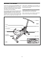
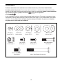
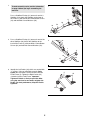
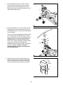
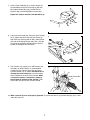
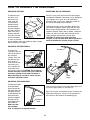
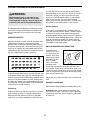
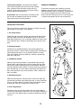
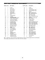
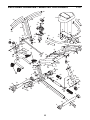
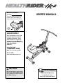
Model No. HRCR4896.0
Serial No.
USER'S MANUAL
The serial number is found in the
location shown below. Write the
serial number in the space above.
Serial
Number
Decal
QUESTIONS?
As a manufacturer, we are committed to providing complete
customer satisfaction. If you
have questions, or if parts are
damaged or missing, PLEASE
CONTACT OUR CUSTOMER SERVICE DEPARTMENT
DIRECTLY.
CALL TOLL-FREE:
1-888-922-4222
Mon.–Fri., 6 a.m.–6 p.m. MST
ON THE WEB:
www.healthriderservice.com
CAUTION
Read all precautions and instructions in this manual before using
this equipment. Keep this manual
for future reference.
Visit our website at
www.healthrider.com
new products, prizes,
fitness tips, and much more!
TABLE OF CONTENTS
IMPORTANT PRECAUTIONS . . . . . . . . . . . . . . . . . . . . . . . . . . . . . . . . . . . . . . . . . . . . . . . . . . . . . . . . . . . . . . . .2
BEFORE YOU BEGIN . . . . . . . . . . . . . . . . . . . . . . . . . . . . . . . . . . . . . . . . . . . . . . . . . . . . . . . . . . . . . . . . . . . . . .3
ASSEMBLY . . . . . . . . . . . . . . . . . . . . . . . . . . . . . . . . . . . . . . . . . . . . . . . . . . . . . . . . . . . . . . . . . . . . . . . . . . . . . . .4
HOW TO OPERATE THE EXERCISER . . . . . . . . . . . . . . . . . . . . . . . . . . . . . . . . . . . . . . . . . . . . . . . . . . . . . . . . .8
MAINTENANCE AND TROUBLESHOOTING . . . . . . . . . . . . . . . . . . . . . . . . . . . . . . . . . . . . . . . . . . . . . . . . . . .10
CONDITIONING GUIDELINES . . . . . . . . . . . . . . . . . . . . . . . . . . . . . . . . . . . . . . . . . . . . . . . . . . . . . . . . . . . . . . .11
PART LIST . . . . . . . . . . . . . . . . . . . . . . . . . . . . . . . . . . . . . . . . . . . . . . . . . . . . . . . . . . . . . . . . . . . . . . . . . . . . . .14
EXPLODED DRAWING . . . . . . . . . . . . . . . . . . . . . . . . . . . . . . . . . . . . . . . . . . . . . . . . . . . . . . . . . . . . . . . . . . . .15
ORDERING REPLACEMENT PARTS . . . . . . . . . . . . . . . . . . . . . . . . . . . . . . . . . . . . . . . . . . . . . . . . . .Back Cover
LIMITED WARRANTY . . . . . . . . . . . . . . . . . . . . . . . . . . . . . . . . . . . . . . . . . . . . . . . . . . . . . . . . . . . . . .Back Cover
IMPORTANT PRECAUTIONS
WARNING:
To reduce the risk of serious injury, read the following important precautions before using the exerciser.
1. Read all instructions in this manual and all
warnings on the exerciser before using the
exerciser.
7. When exercising, do not wear loose clothes
that could become caught on the exerciser.
Always wear athletic shoes to protect your
feet.
2. It is the responsibility of the owner to ensure
that all users of the exerciser are adequately
informed of all precautions.
8. Keep children under the age of 12 and pets
away from the exerciser at all times.
3. Use the exerciser only as described in this
manual.
9. The exerciser should not be used by persons
weighing more than 400 pounds.
4. The exerciser is intended for home use only.
Do not use the exerciser in a commercial,
rental, or institutional setting.
10. Do not operate the exerciser without the
cylinder shields in place.
11. Keep your back straight while using the
exerciser; do not arch your back.
5. Keep the exerciser indoors, away from moisture and dust. Place the exerciser on a level
surface, with a mat beneath it to protect the
floor or carpet. Make sure that there is
enough clearance around the exerciser to
mount, dismount, and use it.
12. If you feel pain or dizziness while exercising,
stop immediately and cool down.
13. The decal shown on page 3 has been placed
on the exerciser. If the decal is missing or
illegible, call the toll-free telephone number
on the front cover of this manual and order a
free replacement decal. Apply the decal in
the location shown.
6. Regularly inspect and tighten all parts of the
exerciser.
WARNING:
Before beginning this or any exercise program, consult your physician.
This is especially important for persons over the age of 35 or persons with pre-existing health problems. Read all instructions before using. ICON assumes no responsibility for personal injury or
property damage sustained by or through the use of this product.
HEALTHRIDER is a registered trademark of ICON IP, Inc.
2
BEFORE YOU BEGIN
Thank you for selecting the new HEALTHRIDER® HR2
exerciser. The HEALTHRIDER HR2 exerciser offers a
unique form of low-impact exercise that uses both the
upper body and the lower body for greater cardiovascular benefits and increased toning.
model number is HRCR4896.0. The serial number can
be found on a decal attached to the exerciser (see the
front cover of this manual).
To avoid a registration fee for any service needed
under warranty, you must register the exerciser at
www.healthriderservice.com/registration.
For your benefit, read this manual carefully before
you use the exerciser. If you have questions after
reading this manual, please see the front cover of this
manual. To help us assist you, note the product model
number and serial number before contacting us. The
Before reading further, please familiarize yourself with
the parts that are labeled in the drawing below.
Handlebar
FRONT
Console
Handlebar Knob
Collar
Seat Handlebar
Seat
Upper Pedal
Seat Knob
(beneath Seat)
Lower Pedal
REAR
3
ASSEMBLY
To hire an authorized service technician to assemble the exerciser, call toll-free 1-800-445-2480.
Assembly requires two persons. Place all parts of the exerciser in a cleared area and remove the packing
materials. Do not dispose of the packing materials until assembly is completed. In addition to the included hex
keys, assembly requires a phillips screwdriver
and an adjustable
wrench
.
As you assemble the exerciser, use the drawings below to identify small parts. The number in parentheses below
each drawing is the key number of the part, from the PART LIST on page 14. The second number is the quantity
needed for assembly. Note: Some small parts may have been pre-assembled. If a part is not in the parts
bag, check to see if it has been pre-assembled.
M6 Spring
Washer (56)–1
M8 Nylon
Locknut (40)–4
M8 Curved
Washer (60)–4
M10 Spring
Washer (57)–2
M6 x 10mm
Screw (55)–1
M10 x 15mm Button
Screw (48)–2
M10 Washer
(58)–2
M6 x 16mm
Screw (41)–4
M10 Curved
Washer (59)–4
M8 x 40mm Button
Bolt (39)–4
M10 x 75mm Button Screw (42)–4
4
1.
1
To make assembly easier, read the information
on page 4 before you begin assembling the
exerciser.
Press a Stabilizer Endcap (11) onto each end of a
Stabilizer (10). Attach the Stabilizer to the front of
the Frame (1) with two M10 x 75mm Button Screws
(42) and two M10 Curved Washers (59).
11
10
59
42
59
2. Press a Stabilizer Endcap (11) onto each end of the
other Stabilizer (10). Attach the Stabilizer to the
back of the Frame (1) with two M10 x 75mm Button
Screws (42) and two M10 Curved Washers (59).
1
11
2
1
11
10
59
11
59
3. Identify the Left Pedals (24), which are marked with
“L” stickers. Using an adjustable wrench, firmly
tighten the Left Pedals counterclockwise into the
Pedal Frame (5). Tighten the Right Pedals (25)
clockwise into the Pedal Frame. Important:
Tighten all Pedals as firmly as possible. After
using the exerciser for one week, retighten the
Pedals. For best performance, keep the Pedals
tightened.
3
5
25
24
5
42
4. Orient the Pedal Frame (5) as shown, and then
insert the Pedal Frame into the Pivot Frame (6).
Attach the Pedal Frame with two M10 x 15mm
Button Screws (48), two M10 Spring Washers (57),
and two M10 Washers (58).
4
58 57
6
48
5
5. Orient the Handlebar (7) as shown. Next, slide the
Handlebar Sleeve (31) downward until the tab on
the Handlebar Sleeve is covering the indicated hole
in the Handlebar.
5
Loosen and remove the Handlebar Knob (28). Next,
press the tab on the Handlebar Sleeve (31) and
insert the Handlebar (7) and the Handlebar Sleeve
into the Frame (1); make sure that the tab on the
Handlebar Sleeve is in the indicated slot in the
Frame. Then, slide the Handlebar upward or downward to the desired height, and tighten the
Handlebar Knob into the Frame and an adjustment
hole in the Handlebar. Make sure that the
Handlebar Knob is engaged in an adjustment
hole in the Handlebar.
6. Orient the Seat (8) and the Seat Carriage (3) as
shown. Attach the Seat to the Seat Carriage with
four M6 x 16mm Screws (41). Note: The Screws
may be preattached to the underside of the Seat.
7
31
Tab
Hole
28
Slot
1
6
8
3
41
41
6
7. Orient a Seat Handlebar (9) as shown. Attach the
Seat Handlebar to the Seat Carriage (3) with two
M8 x 40mm Button Bolts (39), two M8 Curved
Washers (60), and two M8 Nylon Locknuts (40).
7
9
Repeat this step for the other Seat Handlebar (9).
3
60
60
40
9
8. Loosen the Seat Knob (29). Orient the Seat Carriage
(3) as shown and slide it onto the Seat Frame (2).
Attach the Seat Carriage with an M6 x 10mm Screw
(55) and an M6 Spring Washer (56). Then, slide the
Seat Carriage forward or backward to the desired
position and retighten the Seat Knob.
39
8
2
29
56
55
9. The Console (12) requires one “AAA” battery (not
included); an alkaline battery is recommended.
Carefully pry the Console away from the Upper
Console Shroud (13) as shown. Be careful not to
dislodge the reed switch wire. Insert the battery
into the holder on the back of the Console. Make
sure that the battery is oriented as shown by
the diagram on the back of the Console. Then,
reinsert the Console into the Console Shroud.
3
9
12
Reed Switch Wire
13
10. Make sure that all parts are properly tightened. To protect the floor or carpet from damage, place a mat
under the exerciser.
7
HOW TO OPERATE THE EXERCISER
ADJUSTING THE SEAT
EXERCISING ON THE EXERCISER
To adjust the position of the seat,
Seat
loosen the seat
knob, move the
seat forward or
backward to the
desired position,
and then retighten
the knob. To determine if the seat is
properly adjusted,
Seat
sit on the seat and
Knob
pull the handlebar
as close as possible
to your stomach. Your legs should be almost straight,
with your knees bent slightly.
Sit on the seat, place your feet on the lower pedals,
and hold the handlebar. Your hands can be positioned
close together or far apart, or in an overhand or
underhand grip. If necessary, adjust the position of
the seat or the height of the handlebar.
To begin exercising, pull the handlebar toward your
waist while pushing the pedals away with your legs.
Return to the starting position. This completes one
repetition. Repeat, moving with a smooth, continuous
motion. For the best results, move through the full
range of motion and maintain a steady pace.
CAUTION: To avoid injury, keep your back
straight; do not arch your back. Do no operate the
exerciser without the cylinder shields in place.
ADJUSTING THE RESISTANCE
Handlebar
To change the
resistance, turn the
Collar
collar at the front of
Resistance
the resistance
Cylinder
cylinder. There are
ten different resistance levels. A
small arrow on the
side of the resistance cylinder will
show which resistance level is selected. CAUTION: The resistance
cylinder becomes very hot during use. Allow the
resistance cylinder to cool before touching it.
When adjusting the resistance, touch only the
resistance adjustment collar.
Seat
Upper
Pedals
Lower
Pedals
ADJUSTING THE HANDLEBAR
To adjust the height
of the handlebar,
loosen the handlebar knob, move the
handlebar upward
or downward to the
desired position,
Handlebar
and then retighten
the knob into an
Handlebar
adjustment hole in
Knob
the handlebar.
Make sure that
the handlebar
knob is engaged in an adjustment hole.
To focus on the muscles of the upper body, place your
feet on the upper pedals as you exercise.
Note: The console will automatically turn on when you
begin exercising on the exerciser. The operation of
the console is described on the following page.
8
DESCRIPTION OF THE CONSOLE
HOW TO OPERATE THE CONSOLE
The console offers five modes that provide instant
exercise feedback:
1. To turn on the
power, press the
console button or
simply begin
exercising.
• Time—This mode displays the elapsed time. Note: If
you stop exercising for a few seconds, the Time
mode will pause.
Arrow
2. Select the
desired mode:
• Reps/Min—This mode displays your exercise pace,
in repetitions per minute.
To select the
Time, Reps/Min,
Count, or
Calories mode,
Button
press the console
button repeatedly
until an arrow points to the name of the desired
mode. Make sure that the Scan mode is not selected.
• Count—This mode displays the total number of repetitions you have completed, up to 9,999 repetitions.
• Calories—This mode displays the approximate number of calories you have burned.
• Scan—This mode displays the Time, Reps/Min,
Count, and Calories modes, for a few seconds
each, in a repeating cycle.
To select the Scan mode, press the console button
repeatedly. While the Scan mode is selected, an
arrow will show which mode is currently displayed.
To reset the Time, Count, and Calories modes to
zero, hold down the console button for a few seconds.
3. The console has an “auto-off” feature. If the
pedals are not moved and the console button is
not pressed for a few minutes, the power will turn
off automatically to conserve the battery.
9
MAINTENANCE AND TROUBLESHOOTING
Inspect and tighten all parts of the exerciser regularly.
Replace any worn parts immediately.
WHEEL MAINTENANCE
Clean the wheel
and the frame track
on a regular basis.
Use a damp cloth
and mild soap to
remove dust and
debris from the
wheel and the track
on which it travels.
To clean the exerciser, use a damp cloth and a small
amount of mild soap. Important: To prevent damage to
the console, keep liquid away from the console and
keep the console out of direct sunlight. When storing the exerciser, remove the battery from the console.
HOW TO REPLACE THE BATTERY
If the display of the console becomes dim, the “AAA”
battery should be replaced. See step 9 on page 7 and
replace the old battery.
10
Wheel
Track
CONDITIONING GUIDELINES
gy. Only after the first few minutes of exercise does
your body begin to use stored fat calories for energy. If
your goal is to burn fat, adjust your pace until your
heart rate is near the lowest number in your training
zone as you exercise. For increased fat burning,
adjust your pace until your heart rate is near the middle number in your training zone as you exercise.
WARNING:
Before beginning this or any exercise program, consult your physician. This is especially important for persons over the age of 35
or persons with pre-existing health problems.
Aerobic Exercise
The following general guidelines will help you to plan
your exercise program. Remember that proper nutrition and adequate rest are essential for successful
results.
If your goal is to strengthen your cardiovascular system, your exercise must be “aerobic.” Aerobic exercise
is activity that requires large amounts of oxygen for
prolonged periods of time. This increases the demand
on the heart to pump blood to the muscles, and on the
lungs to oxygenate the blood. For aerobic exercise,
adjust your pace until your heart rate is near the highest number in your training zone.
EXERCISE INTENSITY
Whether your goal is to burn fat or to strengthen your
cardiovascular system, the key to achieving the
desired results is to exercise with the proper intensity.
The proper intensity level can be found by using your
heart rate as a guide. The chart below shows recommended heart rates for fat burning, maximum fat burning, and cardiovascular (aerobic) exercise.
HOW TO MEASURE YOUR HEART RATE
To measure your
heart rate, first exercise for at least four
minutes. Then, stop
exercising and place
two fingers on your
wrist as shown.
Take a six-second
heartbeat count,
and multiply the result by 10 to find your heart rate.
For example, if your six-second heartbeat count is 14,
your heart rate is 140 beats per minute. (A six-second
count is used because your heart rate will drop rapidly
when you stop exercising.)
To find the proper heart rate for you, first find your age
at the bottom of the chart (ages are rounded off to the
nearest ten years). Next, find the three numbers above
your age. The three numbers are your “training zone.”
The lower two numbers are recommended heart rates
for fat burning; the highest number is the recommended heart rate for aerobic exercise.
Adjust your pace until your heart rate is at the desired
level.
WORKOUT GUIDELINES
Each workout should include the following three parts:
Fat Burning
A warm-up, with 5 to 10 minutes of stretching and
light exercise. A proper warm-up increases your body
temperature, heart rate, and circulation in preparation
for exercise.
To burn fat effectively, you must exercise at a relatively low intensity level for a sustained period of time.
During the first few minutes of exercise, your body
uses easily accessible carbohydrate calories for ener-
11
Training zone exercise, consisting of 20 to 30 minutes of exercising with your heart rate in your training
zone. (During the first few weeks of your exercise
program, do not keep your heart rate in your training
zone for longer than 20 minutes.)
EXERCISE FREQUENCY
To maintain or improve your condition, plan three
workouts each week, with at least one day of rest
between workouts. After a few months of regular exercise, you may complete up to five workouts each
week, if desired. The key to success is make exercise
a regular and enjoyable part of your everyday life.
A cool-down, with 5 to 10 minutes of stretching. This
will increase the flexibility of your muscles and will
help to prevent post-exercise problems.
SUGGESTED STRETCHES
1
The correct form for several basic stretches is shown at the right.
Move slowly as you stretch—never bounce.
1. Toe Touch Stretch
Stand with your knees bent slightly and slowly bend forward from
your hips. Allow your back and shoulders to relax as you reach
down toward your toes as far as possible. Hold for 15 counts, then
relax. Repeat 3 times. Stretches: Hamstrings, back of knees and
back.
2
2. Hamstring Stretch
Sit with one leg extended. Bring the sole of the opposite foot
toward you and rest it against the inner thigh of your extended leg.
Reach toward your toes as far as possible. Hold for 15 counts,
then relax. Repeat 3 times for both legs. Stretches: Hamstrings,
lower back and groin.
3
3. Calf/Achilles Stretch
With one leg in front of the other, reach forward and place your
hands against a wall. Keep your back leg straight and your back
foot flat on the floor. Bend your front leg, lean forward and move
your hips toward the wall. Hold for 15 counts, then relax. Repeat 3
times for both legs. To cause further stretching of the achilles tendons, bend your back leg as well. Stretches: Calves, achilles tendons and ankles.
4
4. Quadriceps Stretch
With one hand against a wall for balance, reach back and grasp
one foot with your other hand. Bring your heel as close to your buttocks as possible. Hold for 15 counts, then relax. Repeat 3 times
for both legs. Stretches: Quadriceps and hip muscles.
5. Inner Thigh Stretch
Sit with the soles of your feet together and your knees outward.
Pull your feet toward your groin area as far as possible. Hold for 15
counts, then relax. Repeat 3 times. Stretches: Quadriceps and hip
muscles.
12
5
NOTES
13
PART LIST—Model No. HRCR4896.0
Key No. Qty.
1
2
3
4
5
6
7
8
9
10
11
12
13
14
15
16
17
18
19
20
21
22
23
24
25
26
27
28
29
30
31
32
1
1
1
1
1
1
1
1
2
2
4
1
1
1
1
1
1
1
1
1
1
1
1
2
2
1
2
1
1
4
1
1
Description
Key No. Qty.
Frame
Seat Frame
Seat Carriage
Wheel Frame
Pedal Frame
Pivot Frame
Handlebar/Post
Seat
Seat Handlebar
Stabilizer
Stabilizer Endcap
Console/Reed Switch Wire
Upper Console Shroud
Left Console Shroud
Right Console Shroud
Left Side Shield
Right Side Shield
Left Frame Shield
Right Frame Shield
Resistance Cylinder
Mounting Bracket
Wheel
Emblem Mount
Left Pedal/Strap
Right Pedal/Strap
Pivot Rod
Bumper
Handlebar Knob
Seat Knob
Handlebar Endcap
Handlebar Sleeve
Handlebar Bushing
33
34
35
36
37
38
39
40
41
42
43
44
45
46
47
48
49
50
51
52
53
54
55
56
57
58
59
60
61
62
#
#
1
1
2
2
1
4
4
4
4
4
8
2
2
2
2
2
1
1
2
2
11
6
1
1
2
8
4
4
1
1
1
3
R1206A
Description
Clamp
Post Foam
Long Handlebar Foam
Short Handlebar Foam
Magnet
M3.5 x 10mm Screw
M8 x 40mm Button Bolt
M8 Nylon Locknut
M6 x 16mm Screw
M10 x 75mm Button Screw
Bushing
M10 x 50mm Union Bolt
Wheel Spacer
Cylinder Spacer
Pivot Bushing
M10 x 15mm Button Screw
M10 x 37mm Union Bolt
M10 x 104mm Union Bolt
M10 x 120mm Button Bolt
M10 Nylon Locknut
M4 x 16mm Screw
M4 x 8mm Screw
M6 x 10mm Screw
M6 Spring Washer
M10 Spring Washer
M10 Washer
M10 Curved Washer
M8 Curved Washer
Long Cylinder Shield
Short Cylinder Shield
User’s Manual
Hex Key
Note: “#” indicates a non-illustrated part. Specifications are subject to change without notice. For information
about ordering replacement parts, see the back cover of this manual.
14
EXPLODED DRAWING—Model No. HRCR4896.0
R1206A
30
12
35
8
36
35
54
34
30
13
7
3
9
30
43
27
27
6
52
58
49
26
37
58 57
48
25
58 57
58
51
56
55
30
54
54
28
40
15
14
9
31
60
41
32
38
40
41
41
53
36
51
58
2
53
50
17
52
43
49
39
40 60
58
50
5
33
29
53
53
53
24
11
53
53
47
4
19
23
43
59
54
44
58
21
20
43
44
59
58
45
45
1
18
42
62
54
10
42
43
47 16
53
22
46
11
61
10
11
11
59
59
42
15
ORDERING REPLACEMENT PARTS
To order replacement parts, see the front cover of this manual. To help us assist you, please be prepared to give
the following information:
• the MODEL NUMBER of the product (HRCR4896.0)
• the NAME of the product (HEALTHRIDER HR2 exerciser)
• the SERIAL NUMBER of the product (see the front cover of this manual)
• the KEY NUMBER and DESCRIPTION of the part(s) (see the PART LIST and the EXPLODED DRAWING on
pages 14 and 15)
LIMITED WARRANTY
ICON Health & Fitness, Inc. (ICON) warrants this product to be free from defects in workmanship and
material, under normal use and service conditions, for a period of ninety (90) days from the date of purchase. This warranty extends only to the original purchaser. ICON's obligation under this warranty is limited to replacing or repairing, at ICON's option, the product through one of its authorized service centers.
All repairs for which warranty claims are made must be pre-authorized by ICON. If the product is shipped
to a service center, freight charges to and from the service center will be the customer’s responsibility. For
in-home service, the customer will be responsible for a minimal trip charge. This warranty does not extend
to any product or damage to a product caused by or attributable to freight damage, abuse, misuse,
improper or abnormal usage or repairs not provided by an ICON authorized service center; products used
for commercial or rental purposes; or products used as store display models. No other warranty beyond
that specifically set forth above is authorized by ICON.
ICON is not responsible or liable for indirect, special or consequential damages arising out of or in connection with the use or performance of the product or damages with respect to any economic loss, loss
of property, loss of revenues or profits, loss of enjoyment or use, costs of removal or installation or other
consequential damages of whatsoever nature. Some states do not allow the exclusion or limitation of incidental or consequential damages. Accordingly, the above limitation may not apply to you.
The warranty extended hereunder is in lieu of any and all other warranties and any implied warranties of
merchantability or fitness for a particular purpose is limited in its scope and duration to the terms set forth
herein. Some states do not allow limitations on how long an implied warranty lasts. Accordingly, the above
limitation may not apply to you.
This warranty gives you specific legal rights. You may also have other rights which vary from state to state.
ICON HEALTH & FITNESS, INC., 1500 S. 1000 W., LOGAN, UT 84321-9813
Part No. 248844 R1206A
Printed in China © 2006 ICON IP, Inc.