1
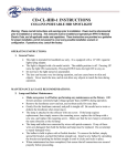
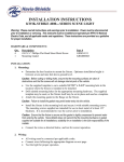
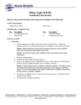
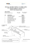
LED Gooseneck Map Light
Installation Instructions
Warning: Please read all instructions and warnings prior to installation of the LED Gooseneck Map Light.
TOOLS REQUIRED:
Phillips Screw Driver
Wire Cutter/Stripper
HARDWARE: (Supplied in Kit)
Qty.
2
2
Description
#6 Machine Screw
#6 Thread Forming Screw
Qty.
2
2
Description
#6 Split Lock Washer
#6 Flat Washer
INSTALLATION:
1. Mounting:
•
A drill template is provided on the back of this instruction sheet. Detach the
template, position it on the desired location for installation, and mark drill locations.
Caution: Before drilling holes, ensure that the mounting surfaces are clear and that the
screws will not damage the internal parts of the console or vehicle.
Caution: Ensure that the Gooseneck Map Light is installed in areas recommended by the
vehicle manufacturer—outside of the airbag zone.
•
•
•
Drill the mounting holes.
Remove the template prior to installing the fixture. Secure the base of the fixture in
position using the supplied machine screws and washers.
The supplied super clip may be used to secure the gooseneck in position if desired.
Caution: Thread forming screws are supplied for alternate installations requiring the fixture to
be mounted from above. If the fixture needs to be disassembled for such installation, please
note that this will void your warranty.
2. Wiring:
•
•
Connect the black lead to negative (ground.)
Connect the red lead to hot (power.)
Note: It is recommended to install an in-line fuse holder and 1 Amp fuse on the red (hot) lead.
•
Test the light for proper operation.
3. Operation:
•
Power is supplied through a three-position switch. The center position is “off,” and
the up and down positions provide red or white light.
4. Troubleshooting:
•
•
•
Use a voltmeter to ensure that the fixture is receiving adequate power. The light
requires nominally 12 VDC for correct operation. Correct any faults found.
A bad ground connection can cause improper operation. Use a negative wire instead
of connecting power to the vehicle chassis to avoid any ground issues.
The light will not be able to turn on if polarity is reversed.
+12 VDC
Power
1A Fuse
(Recommended)
HOT - RED
COMMON - BLACK
Note:
Fuse, fuse holder, and connector are
not supplied by Havis-Shields.
User-Supplied
Connector
Ground
(Optional)
To Switch,
Circuit and
LEDs
Clip Here
Clip Here
TEMPLATE:
∅0.16 (5/32” Drill)
Mounting Holes
∅0.50 (1/2” Drill)
Wireway
21/32
1-23/32
H:\Cons\Misc\LED-Map-Light-Inst-8-08.doc