1
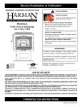
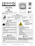
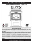
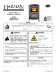
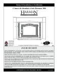
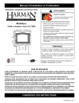
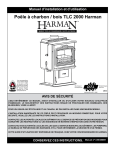
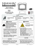
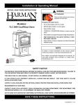
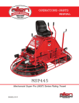
Installation & Operating Manual
The TL300 Top Loading Wood Stove
EPA Certified by
OMNI-Test Laboratories
R5
SAFETY NOTICE
Please read this entire manual before you install and use your new room heater. Failure
to follow instructions may result in property damage, bodily injury, or even death.
FOR USE IN THE U.S. AND CANADA. Suitable for installation in a mobile home(us only).
IF THIS wood-burning STOVE IS NOT PROPERLY INSTALLED, A HOUSE FIRE MAY RESULT. FOR YOUR SAFETY,
FOLLOW INSTALLATION DIRECTIONS.
CONTACT LOCAL BUILDING OR FIRE OFFICIALS ABOUT RESTRICTIONS AND INSTALLATION INSPECTION
REQUIREMENTS IN YOUR AREA.
Contact your local authority (such as municipal building department, fire department, fire
prevention bureau, etc.) to determine the need for a permit.
Cette guide d'utilisation est disponible en francais. Chez votre concessionnaire de Harman
HOME HEATING.
save these instructions.
Manual # 3-90-06901
2
Harman TL300
Index
Introduction
4
Specifications
5
Installation
8
Venting
10
Operation/Building a Fire 16
Maintenance
19
Options
21
Service Parts
22
Warranty
26
Please read this entire manual before you install and use your new heating
appliance. Failure to follow instructions may result in property damage,
bodily injury, or even death.
Hearth & Home Technologies, Inc.
352 Mountain House Road
Halifax, PA 17032 ~ U.S.A.
Harman TL300 3
Introduction
Thank you for purchasing the Harman TL300 Wood Stove. We are confident that you will enjoy the warmth and convenience
of your Harman Stove for decades to come.
With the TL300 you will notice even heat throughout your home and long burn times. This is possible because of
Harman’s special FireDome Non-Catalytic Combustion System, designed into the TL300 to promote clean burning and even
heat output. This equates to unvarying heat over a longer period of time without the temperature peaks and valleys of other
wood stoves. The FireDome continues Harman’s reputation of high efficiency while saving you the expense associated with
catalytic stoves. The top load door makes adding wood easier and allows more wood to fit into the large firebox. You can
view your beautiful fire through the extra large glass door. The glass stays cleaner because of the special IR coated glass and
the exclusive Harman Air Wash System.
The Harman TL300 has an ash pan with its own ash door which allows removal of ashes while the stove is in operation. This
means you can keep a fire all winter if you desire.
The Harman TL300 offers a cooking grill that can be placed in the top of the stove while in operation. This allows you to grill
your favorite meats all year long even when the weather is not suitable for outside grilling. If you haven't already purchased
the cooking grill, you can do so from your Authorized Harman Dealer.
Due to the fact that the TL300 is hot while in operation, gloves should be worn while tending to the fire.
Appliance Certification.
Model: TL300
Test Lab: Omni-Test Laboratories
Report #: 135-S-18-6
Type: Solid Fuel Fireplace Stove or Room Heater
Standard(s): UL 1482, UL 737, ULC-S627
For your reference, please copy
your serial number from the label
on your stove to the box below.
Note: This appliance is also approved for
installation into a shop.
sERIAL nUMBER
LISTED SOLID FUEL FIREPLACE STOVE OR ROOM HEATER
APPAREIL DE CHAUFFAGE OU POELE A COMBUSTIBLE SOLIDE
MODEL/MODELE: TL300
Report#/Rapport # 135-S-18-6
Tested to/Teste a: UL 1482, UL 737
PREVENT HOUSE FIRES: Install and use only in accordance with manufacturer’s installation
and operation instructions and local codes. In absence of any local codes, installation must meet
minimum requirements of NFPA 211 in USA. Refer to manufacturer’s instructions and local codes for
precautions required for passing chimney through a combustible wall or ceiling.
FOR USE WITH SOLID WOOD FUEL ONLY.
Do NOT connect this stove to a chimney serving another appliance.
Flue connector pipe must be 6” diameter, minimum 24 MSG black or 26 MSG blue steel.
Chimney must be factory built UL 103HT or masonry.
NOTE: Replace glass only with 5mm ceramic glass available from your dealer.
Inspect and clean chimney frequently. Under certain conditions of use, creosote buildup may occur
rapidly.
DO NOT OVERFIRE - IF HEATER OR CHIMNEY CONNECTOR GLOWS, IT IS BEING OVERFIRED.
Prevention des incendies:
Respectez scrupuleusement les instructions du constructeur pour l’installation et l’utilisation.
Respectez les regles et normes applicables dans votre region. Dans tous les cas, l’installation devra
au minimum satisfaire aux exigences de NFPA 211 AUX Etats-Unis.
Reportez vous aux instructions du fabricant et aux regles locales pour les precautions necessaires
lors du passage des tuyaux de fumee a travers un mur ou un plafond combustible. Controlez et
nettoyez frequemment la cheminee et les tuyaux de fumee selon les instructions du fabricant.
N’UTILISIXZ QUE DU BOIS EN BUCHES:
Ne pas raccorder ce poele a un conduit de fumee utilise pour un autre appareil.
Le tuyau de fumee doit avoir 6” de diametre minimum, et etre en acier de qualite 24 MSG noir ou
26 MSG bleu.
Le conduit de fumee peut etre maconne ou de fabrication industrielle type ULC S629.
Nota: Ne remplacer la vitre qu’avec une vitre ceramique de 45 mm disponible chez votre fournisseur.
Controlez et nettoyez frequemment la cheminee et les tuyaux de fumee. Dans certaines conditions
d’utilization, des accumulations de cresote peuvent se produire rapidement.
NE PAS SUR CHAUFFER - SI LE POELE OU LE TUYAU ROUGISSENT, VOUS SURCHAUFFEZ
Harman TL300
8” (200 mm)
B
C
SERIAL NUMbER/NUMERO DE SERIE:
Meets requirements of ULC S627-00/Selon les exigences de ULC S627-00
Certified for USA and Canada/Certifie pour les Etats-Unis et le Canada
Room Heater, Solid Fuel Type, Also For Use In Mobile Homes In US only
4
D
F
A
E
Manufactured by / Fabriqué par:
352 Mountain House Road
Halifax, PA 17032 (É.-U.)
ATTENTION:
8”
8”
200mm
200mm
18”
16”
450 mm
CLEARANCE TO COMBUSTIBLE SURFACES
A - Unit to Sidewall
20”
b - Unit to backwall
18”
C - Chimney Connector to Sidewall
31”
D - Chimney Connector to backwall
24”
E - Unit to Adjacent Wall
18”
F - Chimney Connector to Adjacent Wall 27”
DISTANCES MINIMALES DE SECURITE
A - Entre le mur lateral et l’appareil
500 mm
b - Entre le mur arriereet l’appareil
450 mm
C - Entre le tuyau et le mur lateral
775mm
D - Entre le tuyau et le mur arriere
600 mm
E - Entre le mur adjacent et l’appareil 450 mm
F - Entre le tuyau et le mur adjacent 675 mm
Floor protection must be a non-combustible material. Must
also be placed under any horizontal sections of flue connector,
extending 2” (51mm) beyond the measurement of the pipe.
Pour protéger le plancher, il faut sous le poêle un matériau.
Qui doit aussi être placé sous les parties horizontales du tuyau
de raccord à la cheminée et s’étendre à 51 mm (2 po) au-delà
de la mesure du tuyau.
REFER TO MANUFACTURER’S INSTRUCTIONS FOR CLEARANCES WITH ADDITIONAL VENT CONFIGURATIONS.
Veuillez vous référer au manuel d’instruction du manufacturier pour informations additionnels pour la configuration de la ventilation.
CHAUD LORS DU FONCTIONNEMENT.
NE TOUCHEZ PAS L’APPAREIL.GARDEZ LES ENFANTS ET LES
VÊTEMENTS ÉLOIGNÉS. TOUT CONTACT PEUT ENTRAÎNER
DES BRÛLURES DE LA PEAU. RÉFÉREZ-VOUS À LA PLAQUE
SIGNALÉTIQUE ET AU MODE D’EMPLOI. GARDEZ LE MOBILIER
ET LES AUTRES MATÉRIAUX COMBUSTIBLES BIEN À L’ÉCART
DE L’APPAREIL.
Made in U.S.A. of US and imported parts. / Fabriqué aux États-Unis-d’Amérique par des pièces
d’origine américaine et pièces importées.
CONTACT LOCAL BUILDING OR FIRE OFFICIALS ABOUT RESTRICTIONS AND INSTALLATION INSPECTION IN YOUR AREA.
CONSULTEX LES ADMINISTRATIONS ET ORGANISMES COMPETENTS POUR LA CONSTRUCTION ET LA PREVENTION DES
INCEDIES AFIN DE RESPECTER LES REGLES DE SECURITE EN VIGUEUR.
CAUTION:
HOT WHILE IN OPERATION. DO
NOT TOUCH. KEEP CHILDREN AND CLOTHING AWAY.
CONTACT MAY CAUSE SKIN BURNS. SEE NAMEPLATE
AND INSTRUCTIONS. KEEP FURNISHINGS AND OTHER
COMBUSTIBLE MATERIALS A CONSIDERABLE DISTANCE
AWAY FROM THIS APPLIANCE.
U.S. ENVIRONMENTAL PROTECTION AGENCY
Certified to comply with July 1990 particulate emission standards.
Date of Manufacture/Date de fabrication:
2011 2012 2013 JAN FEB MAR APR MAY JUN JUL AUG SEP OCT NOV DEC
326 mm
935 mm
583 mm
Specifications
734 mm
Weight
525 Lbs
Flue Size
6 inch
Log Length Recommended
18 in. / 20 in. Max
Heating Capacity
1,500 - 3000 sq. ft.
Average Emissions
1.1 Grams Per Hr.
Emissons on Low
0.8 Grams Per Hr.
Outside Air Size
3 or 4 inch
223 mm
675 mm
SAFETY NOTICE: IF THIS STOVE IS NOT PROPERLY INSTALLED,
A HOUSE FIRE MAY RESULT. FOR YOUR SAFETY, FOLLOW THE
INSTALLATION DIRECTIONS. CONTACT LOCAL BUILDING OR
FIRE OFFICIALS ABOUT RESTRICTIONS AND INSTALLATION
INSPECTION REQUIREMENTS IN YOUR AREA.
The Harman TL300 meets the U.S. Environmental Protection Agency’s
emission limits for wood heaters sold after July 1, 1990.
Harman TL300 5
Specifications
Top Load Door
Top Load Opening
Front Load Door
Grate
Top Load Door
Handle
Andirons
Air Control
Ash Door
Front Load Door Latch
Ash Door Latch
6
Harman TL300
Specifications
General Considerations
Draft
Before you install and/or operate your TL300 wood stove,
please read the entire contents of this manual. Pay particular
attention to the explanation of draft and its effect on stove
performance, in the installation section. By following the
installation and operating guidelines, you will ensure proper
draft and gain maximum efficiency and enjoyment from
your stove.
Fuel
Your TL300 burns wood very efficiently. Here are some
guidelines concerning log size and moisture content that will
help you obtain the best performance.
Select dry seasoned wood. For example, it should be
checked or cracked on the ends and not exposed to rain or
extremely damp conditions. Hardwoods are favored because
they are heavier and contain more heating capacity (BTU’s)
per load than do softwoods. Wood should be split and stored
under cover for “seasoning” - a year is recommended. Your
stove is not an incinerator - do not burn garbage, painted or
treated wood, plastics, or other debris.
Keep the area around the stove free from clutter. Keep
all combustibles, including fuel, beyond the code-required
clearance distance (48" or 1215 mm in the U.S., 1525 mm
or 60" in Canada). Never store fuel in front of the stove
where it could interfere with door operation, safe loading,
and ash removal.
Do not burn garbage or flammable fluids such
as gasoline, naptha, or engine oil.
CAUTION:
Always wear fire retardant gloves
when operating the stove.
SAFETY NOTICE
IF THIS HARMAN TL300 STOVE IS NOT
PROPERLY INSTALLED, OPERATED
AND MAINTAINED, A HOUSE FIRE MAY
RESULT. FOR YOUR SAFETY, FOLLOW
INSTALLATION DIRECTIONS. CONTACT
LOCAL BUILDING OR FIRE OFFICIALS
ABOUT RESTRICTIONS AND INSTALLATION INSPECTION REQUIREMENTS IN
YOUR AREA.
The Stove
Doors
Your stove has a large glass-paneled door for loading and
fire viewing, a separate smaller door for removing ashes, and
a top loading door.
Front Door
Before opening, always check for wood, embers, or ash
that may be ready to fall out of the door.
To open the glass door, open bypass damper first, by pulling
forward on the top load door handle, to the first position. Then
lift up on the front door handle to disengage the latch, and pull
out. To close the door, push door closed with handle in the
open position, then push handle down to engage the latch.
Ash Door
To open the ash door, open the bypass damper first. Lift up
on the ash door handle and pull it open. Close the door by
pushing in and pushing the handle all the way down.
Top Load Door
To open the top load door, pull forward on the top load
door handle. The first position tells you the bypass damper is
open. Continue pivoting the handle toward you until it locks
the top load door open.
All doors must be closed while the stove is in normal
operation, and the gaskets routinely examined for wear and
replaced when necessary. Good door seals are important for
maintaining control of the stove. Never operate with the ash
door open. Operating the stove with the ash door open, or with
a door improperly sealed, could create a serious overfiring
condition (discussed later in this section).
NEVER OPERATE WITH MORE THAN
ONE DOOR OPEN AT A TIME.
The glass used in your TL300 is manufactured to exact
standards to withstand the high heat of the fire, but like all
glass, it must be treated with common sense and care. Never
abuse the glass by slamming the door shut or striking the glass
with a heavy object. If the glass is broken or damaged, do not
operate the stove until it has been replaced (See instructions
in Maintenance section.)
Grates
The Harman TL300 has a unique grate system that consists
of one bottom grate, and two front andirons. The bottom grate
has slots which allow the ash to fall into the ash pan by passing
a poker back and forth across the grate. The andirons keep
the fuel from coming into direct contact with the glass, and
keep hot coals and embers from spilling out while reloading.
Never build a fire directly against the glass. Andiron extensions (included with each stove) clip onto the fixed andirons
and serve to protect the glass when top loading is used as
the primary loading method. The grates and andirons must
remain in place at all times. Do not tamper with or change
the configuration of this grate system.
Harman TL300
7
Installation
Clearances
Parallel versus Corner Installations
A parallel installation is one in which the back and sides of
the stove are parallel to the walls behind and to the side of the
stove. A corner installation is one in which the back of the
stove is positioned diagonally across a corner of the room.
Each installation requires its own set of clearances.
For parallel installations, the required clearance distances
from the stove are:
1) to the side wall, 20" (508 mm);
2) to the back wall, 18" (458 mm).
3) From the chimney connector to the wall, 31"(787 mm)
4) Hortizontal pipe to the ceiling, 15"(381 mm).
NOTE: For a vertical chimney connector in a parallel installation the distance from the connector to the side wall must
be 31"(787 mm), due to the required side clearance of the
stove itself. Fireplace installations must meet these same
clearance requirements; specifically follow these guidelines
for mantel and trim clearances.
For corner installations, the clearance distances from the
stove are 18"(458 mm) from each corner of the stove measured straight to the nearest combustible material, and 27"
(686 mm) from the chimney connector to the walls.
From the front of the stove, clearance to combustible materials such as furniture, curtains, fuel, etc.: 48"(1220 mm)
in the U.S. and 60"(1524 mm) in Canada. Due to excessive
heat build-up at the wall passthrough, using double wall
pipe, horizontal venting is only approved into a masonry
chimney.
See Detailed Clearances on Page 9
Floor Protection
Floor protection is required under your TL300. This floor
protection must be a minimum of 20 ga. sheet metal in thickness, it can also be stone or tile or other masonry material,
providing it is non-combustible. This floor protection must
extend 18 inches in front of the door opening and 8 inches to
each side and to the rear of the stove body. There must also
be floor protection under any horizontal sections of venting
regardless of their height from the floor.
8
Harman TL300
8" (200 mm)
51" (1275 mm)
Clearance is the empty space required between the stove
or chimney connector and the nearest combustible surface or
object, such as walls, ceilings, floors, or furniture. Clearance
distances may only be reduced by using methods approved
by either the CAN/CSA B365 standard (Canada) or NFPA
211 (U.S.) Contact your building authority for information
if you are interested in reducing clearance distances below
those presented here.
44" (1100 mm)
8"
8"
(200 mm)
(200 mm)
18" (450 mm)
floor protector/ protection de sol (Min. 51" x 44")
Mobile Home Installation
The TL300 is approved for mobile home installations in
the US only. Mobile Home installation should be done in accordance with the Manufactured Home and Safety Standard
(HUD), CFR 3280, part 24.
When installing the TL300 in a mobile home, several requirements must be met:
1. The unit must be bolted to the floor. This can be done
through the rear of the pedestal with 3" lag screws, using the
holes where the unit was bolted to the shipping pallet.
2. The unit must be connected to outside air. See Outside
air section on page 21.
3. Floor protection and specified clearances to combustibles must be followed.
4. Unit must be grounded to the metal frame of the mobile home.
5. Smoke detectors and/or smoke alarms are recommended on each floor of the house. Note that when loading
fire, some smoke seepage may occur, and set off the alarm.
Ventilate as necessary to eliminate the problem. If the alarm
should sound otherwise, cease the use of the appliance and
call your dealer for service.
MOBILE HOME REGULATIONS DO NOT
ALLOW INSTALLATION IN ANY ROOM
DESIGNATED FOR SLEEPING.
Installation/Clearances
Single Wall Pipe - Parallel Installation
15"* 375 mm
31"
(775 mm)
31"
2'(50 mm)
(775 mm)
23"
(575 mm)
20"
(500 mm)
17"
425 mm
Top Vent to vented out side wall
with 90o elbow
Top vent ceiling and sidewall
clearances
24"
(600 mm)
23"
18"
(450 mm)
(575 mm)
Damper Open
Top vent vented
out back wall
Damper Closed
with 90o elbow.
17"
425 mm)
31"
(775 mm)
20"
(500 mm)
Single Wall
PipeWall
- Top
Vent
- Parallel
Installation
Double
Pipe
- Parallel
Installation
11"*(275 mm)
28"
28"
(700 mm)
(700 mm)
2'(50 mm)
21"
17"
(425 mm)
15"
Top Vent vented out side wall
with 90 o elbow.*Masonry
Chimney Only.
Top vent ceiling and sidewall
clearances
18.5"
(925 mm)
21"
13"
(325 mm)
(525 mm)
Damper Open
15"
Top vent vented
out back wall
Damper Closed
with 90o elbow.* Masonry Chimney Only.
(375 mm)
28"
(700 mm)
17"
(425 mm)
18"
(450 mm)
27"
(675 mm)
27"
(675 mm)
18"
(450 mm)
Double Wall Pipe
Single Wall Pipe
Corner Installation with Single and Double Wall Pipe
18"
(450 mm)
27"
(675 mm)
27"
(675 mm)
18"
(450 mm)
*Check with your
local building codes
for clearance.
Harman TL300 9
Venting
Chimney Connectors and Chimneys
Draft
Draft is widely misunderstood. It is important that you,
the stove operator, realize that draft is a variable effect, not
a given quantity. Stoves and chimneys do not have draft, yet
draft is the key to your stove’s performance.
Draft is a force, produced by an operating stove and
the chimney to which it is attached. It is created by hot
gases rising up the chimney, creating a pressure difference
between the inside of your home and the outside air. It continually moves fresh combustion air into the stove, and hot
exhaust gases out of the stove; without this constant flow,
the fire will go out.
Other factors, such as barometric pressure, winds, the
tightness of the home, the total inside chimney volume,
chimney height and the presence of venting devices such
as exhaust fans also play a role in maintaining an adequate
draft. Low barometric pressures, super insulated homes,
and exhaust fans can reduce draft; winds can play havoc
with draft; and too large or too small a chimney volume
can cause reduced draft due to the excessive cooling or
not enough room to vent the exhaust gases. Introducing
outside air directly to the stove may help remedy a low
draft problem. Some signs of inadequate draft are smoking,
odor, difficulty in maintaining the fire, and low heat output.
Overdraft can be caused by a very tall chimney even if it
is the recommended size, and can cause overfiring of your
stove. Signs of an overdraft include rapid fuel consumption,
inability to slow the fire, and parts of the stove or chimney
connector glowing red. It is important that you follow the
chimney guidelines in this manual, including size, type, and
height to avoid draft problems.
When installed and operated according to this manual, the
TL300 will produce enough hot gases to keep the chimney
warm so that adequate draft is maintained throughout the
burn cycle.
Chimney Connectors
In general, following these guidelines will ensure compliance with all national and provincial codes; prior to beginning your installation, check with your local building code
official(s) regarding any additional local requirements or
regulations which may influence the design and placement
of your venting system.
The Harman TL300 may be installed with (.6 mm) 24
gauge chimney connector pipe. The size of the connector
should correspond to the size of the flue collar opening. Do
not use makeshift components.
10
Harman TL300
No part of the chimney connector may pass through an attic
or roof space, closet or other concealed space, or through a
floor or ceiling. Whenever possible, avoid passing the connector through a combustible wall; if you must, use an approved
wall pass-through, described later in this section.
Assemble the connector beginning at the flue collar, with
the crimped ends pointing towards the stove (to keep debris
and creosote flakes inside the system). Each joint, including
the one to the stove’s flue collar and the one to the chimney
itself should be secured with at least three sheet metal screws.
Screws may be a maximum of 3 inches apart. A 1-1/4" (32
mm) overlap is required at each joint, including the flue collar
attachment. No more than two 90 degree elbows should be
used, and the total length of connector should not exceed 10
feet (3m) All horizontal runs of connector must have a minimum upward slope of 1/4 inch per foot (20 mm per meter).
Wall Pass-thrus
Occasionally it is necessary to pass the chimney connector
through a combustible wall to reach the chimney. Depending
on your local building codes, and the pertinent provincial or
national codes, there are several choices for accomplishing
this safely. Before beginning your installation, contact local
officials, and also the chimney connector and chimney
manufacturer for specific requirements.
Canada. Three methods are approved by the Canadian
Standards Association. The diagram shows one method
requiring an 18" (460 mm) air space between the connector
and the wall. It allows use of one or two covers as described in
the diagram. The other two methods are described in detail in
the current issue of CAN/CSA B365, the national standard.
United States In the U.S., the national code is NFPA 211.
While many localities adopt this standard, be sure to check
with local authorities before beginning your installation.
The NFPA (National Fire Protection Association) permits
four methods for passing through a combustible wall. A
commonly used method to pass through a wall directly to a
masonry chimney is to clear a minimum 12"(305 mm) around
the entire chimney connector, and fill it with brick masonry
which is at least 3.5"(90 mm) thick. A fireclay liner, minimum
3/8" (9 mm) wall thickness must run through the brick wall
to the chimney liner (but not beyond the inner surface of the
liner). It must be cemented in place with refractory cement.
This method is illustrated. For details on the other three
options, refer to the most recent edition of the NFPA 211
code.
Venting
Closest
Combustible
Material
Minimum 2" (50mm)
Clearance to Brick
Liner
Chimney Flue
Hole with a minimum
clearance of 18" (450 mm)
between connector and wall.
Non-combustible cover, one
side only. If two covers are
used, each must be mounted
on non-combustible spacers
at least 7/8" (21mm) away
from the wall.
1" (25mm)
Clearance
AN APPROVED CANADIAN
WALL PASS-THROUGH
Minimum 12"
(300mm) to Brick
Fire Clay
Thimble
Chimney
Connector
Masonry Chimney Built to
NFPA 211 Specifications.
Minimum 12" (300mm)
to Combustibles
AN APPROVED U.S.
WALL PASS-THROUGH
The Chimney
The TL300 must be installed into a chimney approved for
use with solid-fuel appliances. In the U.S., the TL300 must
be connected to (1) a prefabricated chimney complying with
the requirements for Type HT chimneys in the Standard for
Chimneys, Factory-Built, Residential Type and Building
Heating Appliances, UL 103, or (2) a code-approved masonry
chimney with a flue liner.
In Canada, the TL300 is listed for use with prefabricated
chimneys tested and listed to the high temperature (650
degrees C) chimney standard, ULC S-629, or with a code
approved masonry chimney.
For mobile homes,(US only) the TL300 must only be
installed with prefabricated chimney systems, including
the installation components, tested to use in mobile homes;
the diameter should match the diameter of the flue collar
opening
The minimum recommended height for any chimney
is 16 ft (4.8 m) above flue collar height. For non-mobile
home installations, a round flue (either masonry or approved
prefabricated), of either 6" (150 mm), 7" (180 mm) or 8"
(200 mm) may be used. For square or rectangular masonry
chimneys, nominal sizes of 8" x 8" or 8"x 12" (200mm x
200 mm, 200 mm x 300 mm) may be used.
Codes require that solid-fuel chimneys extend 3 ft (0.9
m) above the highest point at which they exit from the roof.
Then, the chimney must extend 2 ft.(6 m) above the highest
point within a 10 ft (3 m) radius. Thus, the 3 foot, 2 foot, 10
foot rule: 3ft. - Above roof exit point
2ft. - Higher than anything within10ft. of the chimney.
Do not connect this unit to a chimney
flue servicing another appliance.
NOTE: The restriction of not venting more than one appliance
to the same flue applies to the U.S. specifically. While it is not
recommended that you use the same chimney for more than
one appliance, in Canada certain exceptions may be made.
Be sure to contact your building code inspection official to
see if this option is allowed in your area, and to find out the
specific requirements for such an installation.
More Than 10 ft. (3m)
10 ft. (3m)
2 ft. (0.6m) min.
Ridge
Height Necessary
Above Any Roof Surface Within 10ft. (3m)
3ft. (0.9m)
minimum
above
exit
point
Chimney
The 3-foot, 2-foot, 10 foot rule
Harman TL300 11
Venting
Existing Masonry Chimneys
If you plan on using a pre-existing masonry chimney, have
it thoroughly inspected and cleaned. Any faults which make
the chimney unsafe and unusable must be repaired prior to
use. These can include improper height, structural defects,
blockages, inadequate clearance to combustibles, unsealed
openings into other rooms of the house, signs of creosote or
smoke leakage, a loose or absent clean-out door, or absence
of a liner.
Do not connect to any air distribution
duct or system
Venting to a Masonry Chimney
When connecting to a masonry chimney, several provisions
are standard. First, whether the chimney connector is vented
to the chimney through a thimble or a breech pipe, neither
must pass beyond the inner surface of the chimney liner, and
both must be firmly cemented in place with refractory cement.
(A thimble is a masonry pipe which is inserted through the
chimney wall, and is frequently the preferred method; a breech
pipe is a piece of steel pipe used the same way.) In Canada,
a breech pipe has ridges or protrusions to lock it firmly into
the refractory cement. In either case, the chimney connector
vents to the chimney through the thimble or breech pipe.
Using a thimble, the connector slides completely inside the
masonry to the inner edge of the flue liner, and may be easily removed for chimney and connector inspection. A breech
pipe must extend at least 2" (50 mm) into the room, so the
connector can be attached with sheetmetal screws.
Venting to a Masonry Fireplace Chimney
In some situations, a code compliant chimney originally
used for a masonry fireplace may be used to install your
TL300. In addition to the requirements found in the previous paragraphs, it is important to be aware that all clearances
must be met, including those from the chimney connector to
combustibles. Do not forget to include floor protection in
your plans. (See Clearances and Floor Protection in this section.) Since many fireplaces have exposed wooden mantels
and trim, pay special attention to the clearances necessary to
these materials.
If your fireplace chimney is behind a combustible wall,
you must use an approved wall pass-through system to gain
access to the masonry chimney. The chimney connector must
enter the chimney at a place where it is lined, and the fireplace
must be made inoperable. For example, you might remove
the damper, replacing it with a secure, airtight, noncombustible seal (removable for inspection); this also satisfies the
requirement that no room air must be allowed to enter the
chimney.
12
Harman TL300
Do not burn any fuel other than wood, such as charcoal,
which can cause increased carbon monoxide production or
overfiring. Never use highly volatile substances in your stove,
such as gasoline, which could cause an explosion.
When solid fuels are burned completely, they produce water
and carbon dioxide. However, in long slow burns, a substantial
amount of carbon monoxide may be produced. If allowed
to build up, carbon monoxide (which is odorless) can prove
fatally poisonous. Proper ventilation and draft will prevent this
from happening. If you smell smoke, turn up the air control
lever setting, and thoroughly ventilate your dwelling. During
future burns, be careful not to overload the stove with fuel,
so you will not be tempted to constantly operate at a low air
control setting.
Other causes of poor ventilation or draft are icing, exhaust
fans, a blocked outside air inlet, and room air starvation. If
your stove is sluggish and you get occasional odor, check these
possibilities and increase the air flow in your home.
Installing to a Prefabricated Chimney
When venting your TL300 using a prefabricated chimney,
be sure to contact local building code authorities, and to follow the manufacturer’s instructions exactly. Use only the
manufacturer’s parts; do not use makeshift installation techniques. All prefabricated chimneys must be tested to either
the U.S. or Canadian high-temperature standards, UL 103 or
ULC S629.
The Harman TL300 was tested with the fuel
door open and closed. Keep door closed for
normal operating conditions. If you operate
with the door open, open the by-pass damper
and put a screen over the door opening.
Venting
Standard Ceiling Installation with
Factory Built Chimney
Cathedral Ceiling Installation with
Factory Built Chimney
Harman TL300 13
Venting
Chimney Breach Fireplace Conversion with Non-Combustible Wall
Minimum Clearance
to Unprotected Ceiling
18"
Chimney Connector
Sealed at Thimble
Flue Liner with Required Air Space
Minimum of three Sheet
Metal Screws per Joint of
Chimney Connector
Airtight
insulated
Clean-out
Mantel and Trim
Protection
Floor Protection*
Combustible Floor
* Floor Protection in Accordance
with Solid Fuel Appliance Listing
14
Harman TL300
Damper Closed
and Sealed with
Non-Combustible Material.
Venting
Chimney Breach Fireplace Conversion with Combustible Wall
Minimum Clearance from
Chimney Connector to Unprotected Ceiling
15"**
Flue Liner with Required Air Space
Listed or Approved Thimble Assembly
1" Clearance for Exterior
Chimney or 2" Clearance
for Interior Chimney and 2"
Clearance for NFPA 211-Type
Approved Thimbles
Combustible
Wall
Sheetrock
Airtight
insulated
Clean-out
Mantel &
Trim
Protection
Floor Protection*
Damper Closed
and Sealed with
Noncombustible
Material.
Combustible Floor
* Floor Protecion in Accordance with Solid Fuel Appliance Listing
** Check with your local building codes for clearance.
Harman TL300 15
Operation
The Combustion Process
Combustion in the Harman TL300 is precisely controlled and is divided into two parts.
During combustion, primary air enters at the bottom front of the stove and travels up channels at either
side of the front door. This pre-heated air then enters
the manifold, located above the front door, where it is
released into the firebox as a sheet of air between the
glass and the fire. This air-wash system cleans the glass
as it provides oxygen to the firebox.
Secondary combustion air enters the stove at the bottom rear of the stove. Here, in the "Firedome", it mixes
additional oxygen with the exhaust, causing it to be
re-burned. This secondary combustion is necessary to
achieve and sustain long, clean burning.
During combustion, the burning of wood proceeds
through several stages. The initial or evaporation stage
is where the moisture in the wood is driven off in the
form of steam. During the second stage, the volatile
gases contained in the wood are released and burned.
This represents most of the wood's heating capacity.
The final stage is the charcoal stage where the charcoal
burns the remaining heat content out of the fuel. Ash remains after the burning is complete. Within the primary
firebox, two or more of these stages of combustion are
occurring simultaneously.
Two important controls - the top load door handle and
the air control lever regulate the operation and output
of the stove.
Top loading door handle/damper interlock.The top
loading door handle is linked to the bypass damper and
serves two purposes. Move the handle forward one position (approximately 3") and the handle automatically
opens the bypass damper, you must open the bypass
damper, or smoke will come into the room. In this mode
of operation the combustion gases go directly from the
main combustion chamber to the flue collar and exit
into the chimney.
Continue moving and lifting the handle and it opens
the top loading door.
NOTE: The bypass damper must be open for smokeless loading. Open the bypass damper by pulling the
handle toward the front of the stove.
Damper
Open
Damper Open
Damper
Closed
Damper Closed
Top Load Door Open
16
Harman TL300
Building a Fire
Building and Maintaining the Fire
Do not use chemicals or fluids
to start the fire.
Never use gasoline, gasoline-type lantern fuel,
kerosene, charcoal lighter fluid, or similar liquids
to start or “freshen up” a fire in this heater. Keep
all such liquids well away from the heater while
it is in use.
Minimum
Primary Air
Maximum
Primary Air
Air Control
The air control lever is located directly below the
ash lip of the stove. Using this lever will enable you to
vary the amount of air delivered to the fire, creating a
range of heat outputs. The low heat output setting is to
the left, and high is to the far right. Do not, under any
circumstances, alter the configuration or operation of
the air control lever.
For low burn, slide the air control to the leftmost notch.
For medium burns, use notches 2 or 3. Maximum heat
is attained with the air control all the way to the right.
Do not burn the stove continuously at the maximum
setting. If maximum heat is required day after day,
the stove is too small for the area you are trying to
heat and damage will occur to the stove.
If your wood is not seasoned long enough or is high
in moisture, you may have to adjust the primary air 1
or 2 notches higher to sustain a low burn rate with the
cleanest possible exhaust.
Blower
To regulate the speed of the optional convection
blower, adjust the variable speed control from low to
high by turning the knob located on the blower. The
blower speed should be matched to the air control lever
setting. When the air setting is low, the blower should
always be at the minimum setting. At high settings,
above the first notch on the air control, the blower may
be set to your desired control level. Be sure the blower
cord does not run under, over, or in front of the stove.
Begin with the bypass damper open, and the air
control lever at the maximum setting, all the way to the
right. Be sure the ash pan door is closed and latched.
Start with a bed of crumpled paper and kindling sized
about finger width; place several 1" - 2" (25mm - 50mm)
split pieces of dry wood on top of the kindling, followed by
a few 2" - 3" (50 mm - 80 mm) split pieces. Lay the wood
in a crossed pattern to allow maximum air flow. Ignite
the paper and close the loading door(s). Allow this startup fire to burn for a few minutes, keeping the bypass
damper open. Add about five more pieces of wood in the
2 to 3 inch (50 - 80mm) size range, making sure that the
fuel bed is all the way across the firebox and staggered
to allow airflow. Close the door and allow this loading
to burn a few minutes.
Add increasingly larger pieces of wood to the fire
until you have a thick bed of hot embers, approximately
2 to 3 inches deep at the back of the grate and at least
an inch deep at the front. You must have this charcoal
bed established before you close the bypass damper.
Providing you have the charcoal bed described above,
close the bypass damper by pulling the handle toward
the front of the stove. This will begin the highly efficient mode of operation where the exhaust gases get
re-burned in the secondary combustion package. If you
cannot achieve a charcoal bed within the first 15 to 20
minutes, your wood is likely too wet, and you may need
to burn the fire longer and/or hotter to compensate for
the extra energy needed to drive out the moisture.
If, after five minutes of burning with the damper
closed, smoke is visible coming from the chimney,
you probably do not have the proper coal bed. Open
the bypass damper and continue with the process until
a significant coal bed is formed.
Harman TL300
17
Building a Fire
Building and Maintaining the Fire Cont.
Always remember to open the bypass damper when
you are loading, this allows the exhaust gases to pass
directly into the flue outlet and reduces the chance of
smoke spillage into the room.
Reloading: Once you have prepared and maintained
a thick charcoal bed, and the secondary combustion is
established, you should be able to reload the stove at
any time by simply opening the bypass damper, then
the load door, adding fuel and closing the door then the
damper. This depends on coal bed size, load size and
moisture content of fuel.
Removing Ashes: Before reloading, empty the ash
pan (remember to close the ash door while emptying
the pan). The ashes should be the coolest at this time.
Remove ashes from the fire chamber periodically by
raking a poker across the bottom grates.
Excessive ash buildup can prevent proper venting
of exhaust gases. Do not allow the ash pan to over-fill.
Ash buildup between the ash pan and the bottom of
the grate can cause the grate to overheat and wear out
prematurely.
The TL300 was designed to allow access to the ash
pan without the need for opening the main door. Before
opening the ash door and removing the ash pan, open
the bypass damper. Wearing heavy protective gloves,
open the ash door and remove the ash pan by pulling it
forward by the handle. Close the ash door and damper
bypass before taking the ashes outside for safe disposal.
Ashes should be placed in a metal container with
a tight fitting lid. The closed container of ashes
should be placed on a noncombustible floor or on the
ground, well away from all combustible materials,
pending final disposal. If the ashes are disposed of
by burial in soil or otherwise locally dispersed, they
should be retained in the closed container until all
cinders have thoroughly cooled. (This could take
days).
Never use the ash disposal container for other
trash. Wood ash can be added to your garden or
compost.g
Avoid overfiring your stove.
Overfiring is a potentially hazardous situation which
can lead to overheating of combustible materials, damage to the stove, and in extreme cases, cause a fire.
Overfiring is caused by:
1. Too much air flowing through the stove too quickly.
2. You may have positioned the primary air control lever
too far to the right.
3. Inadvertently leaving the damper or ash pan door open
4. Not keeping up with routine maintenance, such as
checking door gaskets for wear.
Overfiring results in excessive fuel consumption, and
may cause parts of the stove or chimney connector to
glow red. If you notice signs of overfiring, reduce the
air supply to the fire, and review the Maintenance section in this manual.
In the event of a chimney fire, call your
local fire department; make sure everyone is safely out
of the house. Reduce the air intake of the stove as much
as possible using the air control lever; close the bypass
damper to further restrict air flow. Do not throw water
on the fire; this can cause stove damage and create an
even more dangerous situation. Have your chimney
professionally cleaned and inspected before relighting
your stove.
As you begin to operate your stove at higher temperatures, you will notice a “hot” or unpleasant smell;
this is just the paint going through the curing process,
and will disappear after a few fires.
CAUTION
The stove is hot while in operation. Keep children,
clothing and furniture away. Contact may cause
skin burns.
Never leave the stove unattended if either the ash
or load door is open. Overfiring may result.
Risk of Excessive Temperatures. Keep Ash Door
Closed During Firing of the Heater.
CAUTION: Always wear fire-resistant
gloves to operate the stove. The air control
is hot while in operation.
18
Harman TL300
Maintenance
Like all fine equipment, your TL300 requires some
routine maintenance and inspection. Follow the guidelines in this section to assure safe, efficient operation.
The Stove
Surface
The stove’s exterior surface should be dusted
periodically with a soft cloth. For more thorough cleaning, wait until the stove is cool before using a damp
cloth to clean any blemishes.
Controls
To avoid a rust build-up on the inner surfaces of the
controls, work the controls back and forth several times
during the summer or any prolonged period when you
are not using your stove.
The Fire Chamber
The inside of the fire chamber should be examined
for damage to the refractory lining material, grates,
and casting. If any bricks have been damaged, replace
them with Harman replacement parts. Be sure that
all air holes in the refractory are open. The Firedome
combustion package can be examined and/or cleaned
with the bricks removed.
NOTE: Be sure not to insert anything such as a fire
poker into the Combustion Package. Doing this may
cause damage to the combustion package. See below.
Glass - Replacement
If the stove’s glass is cracked or broken, you must
replace it before operating your stove. Remove pieces
carefully. Replace glass only with Harman replacement
glass; do not use substitutes.
To replace the glass panel, you will need to
remove the door. To do this, open the door, lift it straight
up and place it on a soft surface.
Carefully remove damaged glass, gasket material, and
hold down clips (set aside).
Referring to the diagram, note how the various components of the door system fit together. Lay the load
door face down on the soft surface, and install the self
adhesive 1/4"” gasket material around the front face
of the glass. Note: this glass has a special IR coating
on one side. This coating must be to the outside of the
stove. The coated side has a label on it and/or will show
resistance on a ohm meter.
Set the glass panel and gasket gently onto the door.
Install the hold down clips and tighten with bolts as
shown. Reinstall door on stove.
Glass - Cleaning
Sometimes it will be necessary to clean accumulated
ash from the glass surface; allowing this ash to remain
on the glass for long periods can result in “etching” due
to the acidity of the ash. The creosote which accumulates
on the glass should burn off during hot fires.
Never clean the glass while it is hot, and do not use
abrasive substances. Wash the surface with cool water,
and rinse thoroughly. You may wish to use a non-abrasive
cleaner specifically designed for use on stove glass. In
any case, dry thoroughly before relighting your stove.
DO NOT use any
tools or fire poker
within this area.
Harman TL300 19
Maintenance
Gaskets
Gaskets are used at strategic positions when building
the Harman TL300 for controlling the path that incoming and outgoing air and gases take through the stove.
You must check these gaskets from time to time and
replace them when necessary. The gaskets are made
of fiberglass of different sizes (obtainable from your
Harman dealer) and some are fixed in place with a high
temperature stove gasket cement. To change a gasket,
first remove the worn fiberglass and clean the area with
a wire brush. Also clean any other surfaces that come
into contact with the gasket. Place a small bead of cement in the area under the gasket if required, then press
new gasket material into the channel; do not overlap
the ends. Seat the gasket firmly by applying pressure
when possible; for example, after changing the door
gasket, close the door. Allow the cement to dry before
using your stove.
Gaskets are located:
• On the doors to provide airtight closure.
• Between the damper and the damper frame.
• Rear cover
• Rear housing
Damper Ramp Adjustment
After the stove has been in operation for awhile, the
damper gasket may compress and allow the damper
handle to move from the open to the closed position
without the added ramp tension needed to keep the
damper held in the closed position.
To adjust the ramp, the stove MUST be allowed to
go out and cool down.
• After the stove has cooled off, remove the stove pipe
from the stove collar and close the damper.
• Using a flashlight, look into the collar. About midpoint of the damper plate on the backside you will see
the adjustment bolt for the ramp tension. (See figure
on right.)
• You will need (2) 7/16 " wrenches. Use one to hold the
bolt still while using the other to loosen the nut.
• Turn the bolt inward (clockwise facing the head) approximately 1/4 turn and retighten the locknut.
• Now open and close the damper to check for proper
tension on the damper lever while moving into the
closed direction.
• If the tension is incorrect, readjust the bolt.
20
Harman TL300
The Chimney System
Creosote
When wood is burned slowly, it produces tar and other
organic vapors, as well as soot, which combine with
expelled moisture to form creosote. The creosote vapors
condense in the relatively cool chimney flue (associated
with a slow burning fire). As a result, creosote accumulates on the flue lining. When ignited, this creosote can
result in an extremely hot fire.
The FireDome on the TL300 cuts creosote to almost
nothing when properly burned with dry seasoned
wood.
The chimney should be inspected at least once every
two months during the heating season to see if any creosote build-up has occurred. Checking your chimney and
chimney connector more frequently, especially while
you are getting used to your stove, is recommended. To
inspect this system, let the stove cool. Using a flashlight
and mirror, check the interior of the chimney connector,
and the chimney itself. If a significant layer of creosote
or soot has accumulated (1/8" or 3 mm) it should be
removed to reduce the risk of a chimney fire.
To clean deposits from the surface of the connector,
use a stiff wire brush after dismantling the connector assembly. To clean the chimney, use a specially designed
brush sized to fit your particular flue opening, or call an
established chimney cleaning service.
At the end of the heating season, perform a thorough
examination of your chimney system, and have it repaired if necessary.
Loosen nut
Turn bolt inward 1/4 turn.
Options
Cooking Grill- #1-00-08121
The TL300 offers a unique
stainless steel cooking grill that
can easily be taken in and out
of the stove for easy cleaning.
Note: Please use heat resistant
gloves when handling the
cooking grill. Surfaces will
be hot enough to cause physical harm.
Cozy Screen- #3-40-06960
Your Harman TL300 can be burned like a fireplace
with the optional Cozy Screen. The Cozy Screen can
be used with either the door in place or with the door
removed from the stove. When using the Cozy Screen,
the damper bypass must stay in the open position or
smoke spillage will occur.
The Cozy Screen can be used from the start of a fire or
can be used with an existing one. When starting a fire
with the Cozy Screen, smoke spillage may occur until
it develops a draft strong enough to pull all smoke back
into the flue.
Trim Kit- #1-00-06931-7
The brushed stainless steel trim kit adds elegance to the
TL300. The kit includes the
door frame, ash lip trim, and
tile frame.
Outside Air (optional)
The TL300 is designed to accommodate the use of
outside air introduced directly to the stove. The opening
is located at the back of the stove pedestal base. You'll
notice there is a rounded hole with the etching of a larger
hole. The size needed depends on the length of pipe being used.(see below)
Check with your local building inspector to find out
requirements determining if outside air is needed when
installing the TL300 in your area. Some signs to watch
for that indicate a possible need for outside air: Poor
performance of other heaters or of the TL300, including
smoke roll-out and odor; the disappearance of the same
symptoms when a window is opened near the stove;
and condensation on windows in the winter. Modern
homes with tight windows and doors, vapor barriers, and
particularly with exhaust systems are the most likely to
require outside air.
An outside air duct less than 5' (1525 mm) long may
be 3" [80mm] in diameter, and be made of masonry tile,
26 gauge (0.019) galvanized steel, or other approved
noncombustible material; it should have a 1" (25 mm)
clearance to combustibles. Systems longer than 5' (1525
mm), or containing more than two elbows, should have a
4" (100 mm) diameter duct to provide an adequate flow
of combustion air. The air duct must terminate outside
the dwelling and be screened to keep out debris, birds
or animals.
Blower- #1-00-08118
The optional 105 cfm blower helps
circulate heated air throughout the
home. It installs easily onto the
back of the stove, using the included
mounting plate.
3" Outside Air Duct
Harman TL300
21
TL300
Service Parts
beginning Manufacturing date: aug. 2007
ending Manufacturing date: active
Wood Stove
1-90-06900-1 (black), 1-90-06900-2 (charcoal), 1-90-06900-3 (goldenfire), 1-90-06900-4 (Metallic blue),
1-90-06900-5 (honey glo), 1-90-06900-10 (Mojave red), 1-90-06900-12 (Forest green)
1
2
3
8
7
6
5
4
9
14
10
13
11
12
Part number list on following page.
02/11
TL300
Service Parts
beginning Manufacturing date: aug. 2007
ending Manufacturing date: active
IMPORTANT: THIS IS DATED INFORMATION. When requesting service or replacement
parts for your appliance please provide model number and serial number. All parts listed
in this manual may be ordered from an authorized dealer.
iTeM
1
deScriPTion
coMMenTS
Rear Air Jacket
Stocked
at depot
ParT nuMber
1-10-06928P
1/4-20 x 1/2” Grade 8.2 Zinc SAE Flange Bolt
Pkg of 50
3-30-2001-50
Y
2
Combustion Package Cover
2-00-06922L
3
Combustion Package
3-40-06999
Y
Pkg of 2
3-44-06949-2
Y
Pkg of 4
3-44-2500202-4
Y
Combustion Package Base Gasket
4
Gasket, Brick Air
5
Outside Air Plate
2-00-06943P
5/16-18 x 1 1/4” Grade 5 Zinc Plated Hex Cap Screw
Pkg of 50
3-30-1129-50
6
Top Air Grill Assembly
1-10-06946P
7
Top Load Door Assembly
1-10-06921A
Dowel Pin, .250 x .375
Pkg of 15
Gasket. Top Load Door
Qty. 2 req.
Lid Hinge Set, Bottom
Y
3-30-2019-15
1-00-10050
Hinge Spacer
Y
Y
2-00-40021L
1-00-40022
Y
8
Left Side Shield
2-00-06926P
Y
9
Andrion and Andiron Extensions
2-00-05222-1
Y
10
Screw, 5/16-18 x 3/4” Grade 5 Zinc Plated Hex Cap
Pkg of 100
3-30-1125-100
Y
Washer, 5/16” Zinc Plated USS Flat
Pkg of 100
3-30-0204-100
Y
Front Load Door Assembly
1-10-06920A
1-00-249119
Y
Gasket, Glass
1-00-2312
Y
Gasket. Load Door
1-00-00888
Y
Glass, Load Door
3-40-06932
Y
Door Latch
11
Ash Door Assembly
1-10-06915A
Ash Door Latch
3-00-249149
Gasket, Ash door
1-00-10000
Y
12
Bolt on Ash Door Hinge
2-00-06952B
13
Ash Pan
1-10-06938
Y
14
Right Side Shield
2-00-06927P
Y
#15 Kit a
#16 Kit b
15
Kit A (Includes Screws, Steel Sleeve Bushing)
1-00-06902
16
Kit B (Includes Screws, Steel Sleeve Bushing, Latch
Adjuster Plate, Reverse Lock Nut).
1-00-06903
Additional service part numbers appear on following page.
02/11
TL300
Service Parts
beginning Manufacturing date: aug. 2007
ending Manufacturing date: active
IMPORTANT: THIS IS DATED INFORMATION. When requesting service or replacement
parts for your appliance please provide model number and serial number. All parts listed
in this manual may be ordered from an authorized dealer.
iTeM
deScriPTion
coMMenTS
#17 air Slide assembly
Stocked
at depot
ParT nuMber
17.3
17.2
17.1
17.1
Rod Bracket
2-00-06963B
17.2
Air Slide Adjuster
1-10-06964W
17.3
Air Slide Weldment
1-10-06950W
#18 damper arm assembly
18.5
18.6
18.1
18.4
18.7
18.2
18.3
18.8
18.1
Push-On Cap Lift Arm
3-31-500015
18.2
Wooden Knob
3-40-06956
Y
18.3
Damper Linkage Arm Weldment (Includes knob & cap)
1-10-06937W
Y
18.4
Damper Pivot Gear
18.5
Damper Idler Gear
2-00-06923L
Y
18.6
Damper Arm Gear Weldment
1-10-06916W
Y
18.7
Damper Shaft Cover Weldment
1-10-06918W
18.8
Damper Linkage Weldment
1-10-249146
Y
Hardware Package (Includes Drive Arm Washer, Pusher Block
Bushing, Wave Washer, Screws)
1-00-06901
Y
Pkg of 2
2-00-06924-2
Additional service part numbers appear on following page.
02/11
TL300
Service Parts
beginning Manufacturing date: aug. 2007
ending Manufacturing date: active
#19 Firebox assembly
19.1
19.2
19.8
19.7
19.6
19.5
19.3
19.4
19.13
19.11
19.9
19.12
19.10
IMPORTANT: THIS IS DATED INFORMATION. When requesting service or replacement
parts for your appliance please provide model number and serial number. All parts listed
in this manual may be ordered from an authorized dealer.
iTeM
deScriPTion
19.1
Damper Frame Assembly (Includes Damper)
19.2
Rear Brick Clip
19.3
coMMenTS
Stocked
at depot
ParT nuMber
1-10-249106
Y
1-00-249153
Y
Left Inside Plate Assembly
1-10-249117A
Y
19.4
Logo Brick
3-40-00101
Y
19.5
Inlet Brick Left
3-40-00103
Y
19.6
Side Brick Bracket
Pkg of 2
1-00-06945
Y
Pre #551
4-40-86125
Y
Post #551
3-40-86125
Y
Qty. 2 req.
3-40-06944
Y
Pkg of 2
19.7
Fire Brick 6” x 12” (Qty 4 req)
19.8
Brick Insulation
19.9
Grate
2-00-06925B
Y
19.10
Inlet Brick Right
3-40-00104
Y
19.11
Right Inside Plate Assembly
1-10-249118A
Y
19.12
Shoe Brick Gasket
3-44-06951
Y
19.13
Shoe Brick
3-40-00100
Y
Hardware Package (Includes Screws, Centerlock Nuts)
1-00-06900
Y
02/11
This page intentionally left blank.
26
Harman TL300
Hearth & Home Technologies Inc.
LIMITED LIFETIME WARRANTY
Hearth & Home Technologies Inc., on behalf of its hearth brands (”HHT”), extends the following warranty for
HHT gas, wood, pellet, coal and electric hearth appliances that are purchased from an HHT authorized dealer.
WARRANTY COVERAGE:
HHT warrants to the original owner of the HHT appliance at the site of installation, and to any transferee taking ownership
of the appliance at the site of installation within two years following the date of original purchase, that the HHT appliance
will be free from defects in materials and workmanship at the time of manufacture. After installation, if covered components manufactured by HHT are found to be defective in materials or workmanship during the applicable warranty period,
HHT will, at its option, repair or replace the covered components. HHT, at its own discretion, may fully discharge all of its
obligations under such warranties by replacing the product itself or refunding the verified purchase price of the product
itself. The maximum amount recoverable under this warranty is limited to the purchase price of the product. This warranty
is subject to conditions, exclusions and limitations as described below.
WARRANTY PERIOD:
Warranty coverage begins on the date of original purchase. In the case of new home construction, warranty coverage
begins on the date of first occupancy of the dwelling or six months after the sale of the product by an independent,
authorized HHT dealer/ distributor, whichever occurs earlier. The warranty shall commence no later than 24 months
following the date of product shipment from HHT, regardless of the installation or occupancy date. The warranty period for
parts and labor for covered components is produced in the following table.
The term “Limited Lifetime” in the table below is defined as: 20 years from the beginning date of warranty coverage for
gas appliances, and 10 years from the beginning date of warranty coverage for wood, pellet, and coal appliances. These
time periods reflect the minimum expected useful lives of the designated components under normal operating conditions.
Warranty Period
Parts
Labor
1 Year
2 years
HHT Manufactured Appliances and Venting
Gas
X
X
Wood
X
X
X
3 years
Pellet
EPA
Wood
Coal
X
X
X
X
X
X
X
X
X
Components Covered
Electric Venting
X
X
All parts and material except as
covered by Conditions,
Exclusions, and Limitations
listed
Igniters, electronic components,
and glass
Factory-installed blowers
Molded refractory panels
X
Firepots and burnpots
5 years
1 year
7 years
3 years
10
years
1 year
X
Limited
3 years
Lifetime
X
X
X
X
X
90 Days
X
X
X
X
X
X
X
X
Castings and baffles
X
X
Manifold tubes,
HHT chimney and termination
Burners, logs and refractory
Firebox and heat exchanger
X
X
All replacement parts
beyond warranty period
See conditions, exclusions, and limitations on next page.
4021-645C 12-29-10
Page 1 of 2
WARRANTY CONDITIONS:
•
•
•
•
This warranty only covers HHT appliances that are purchased through an HHT authorized dealer or distributor. A list of
HHT authorized dealers is available on the HHT branded websites.
This warranty is only valid while the HHT appliance remains at the site of original installation.
Contact your installing dealer for warranty service. If the installing dealer is unable to provide necessary parts, contact
the nearest HHT authorized dealer or supplier. Additional service fees may apply if you are seeking warranty service
from a dealer other than the dealer from whom you originally purchased the product.
Check with your dealer in advance for any costs to you when arranging a warranty call. Travel and shipping charges
for parts are not covered by this warranty.
WARRANTY EXCLUSIONS:
This warranty does not cover the following:
• Changes in surface finishes as a result of normal use. As a heating appliance, some changes in color of interior and
exterior surface finishes may occur. This is not a flaw and is not covered under warranty.
• Damage to printed, plated, or enameled surfaces caused by fingerprints, accidents, misuse, scratches, melted items,
or other external sources and residues left on the plated surfaces from the use of abrasive cleaners or polishes.
• Repair or replacement of parts that are subject to normal wear and tear during the warranty period. These parts
include: paint, wood, pellet and coal gaskets, firebricks, grates, flame guides, light bulbs, batteries and the discoloration of glass.
• Minor expansion, contraction, or movement of certain parts causing noise. These conditions are normal and complaints related to this noise are not covered by this warranty.
• Damages resulting from: (1) failure to install, operate, or maintain the appliance in accordance with the installation
instructions, operating instructions, and listing agent identification label furnished with the appliance; (2) failure to
install the appliance in accordance with local building codes; (3) shipping or improper handling; (4) improper operation, abuse, misuse, continued operation with damaged, corroded or failed components, accident, or improperly/
incorrectly performed repairs; (5) environmental conditions, inadequate ventilation, negative pressure, or drafting
caused by tightly sealed constructions, insufficient make-up air supply, or handling devices such as exhaust fans or
forced air furnaces or other such causes; (6) use of fuels other than those specified in the operating instructions; (7)
installation or use of components not supplied with the appliance or any other components not expressly authorized
and approved by HHT; (8) modification of the appliance not expressly authorized and approved by HHT in writing;
and/or (9) interruptions or fluctuations of electrical power supply to the appliance.
• Non-HHT venting components, hearth components or other accessories used in conjunction with the appliance.
• Any part of a pre-existing fireplace system in which an insert or a decorative gas appliance is installed.
• HHT’s obligation under this warranty does not extend to the appliance’s capability to heat the desired space. Information is provided to assist the consumer and the dealer in selecting the proper appliance for the application. Consideration must be given to appliance location and configuration, environmental conditions, insulation and air tightness of
the structure.
This warranty is void if:
•
•
•
The appliance has been over-fired or operated in atmospheres contaminated by chlorine, fluorine, or other damaging
chemicals. Over-firing can be identified by, but not limited to, warped plates or tubes, rust colored cast iron, bubbling,
cracking and discoloration of steel or enamel finishes.
The appliance is subjected to prolonged periods of dampness or condensation.
There is any damage to the appliance or other components due to water or weather damage which is the result of, but
not limited to, improper chimney or venting installation.
LIMITATIONS OF LIABILITY:
•
The owner’s exclusive remedy and HHT’s sole obligation under this warranty, under any other warranty, express or
implied, or in contract, tort or otherwise, shall be limited to replacement, repair, or refund, as specified above. In no
event will HHT be liable for any incidental or consequential damages caused by defects in the appliance. Some states
do not allow exclusions or limitation of incidental or consequential damages, so these limitations may not apply to you.
This warranty gives you specific rights; you may also have other rights, which vary from state to state. EXCEPT TO
THE EXTENT PROVIDED BY LAW, HHT MAKES NO EXPRESS WARRANTIES OTHER THAN THE WARRANTY
SPECIFIED HEREIN. THE DURATION OF ANY IMPLIED WARRANTY IS LIMITED TO DURATION OF THE
EXPRESSED WARRANTY SPECIFIED ABOVE.
4021-645C 12-29-10
Page 2 of 2
Notes
Harman TL300 29
Notes
30
Harman TL300
Proudly Printed On 100% Recycled Paper