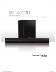
Download Harman Kardon SB 30 User's Manual
Transcript
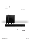
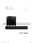
SB 30
Multichannel active soundbar speaker system
Owner’s Manual
SB 30
Important Safety Instructions
Important Safety Instructions
1.
2.
3.
4.
5.
6.
7.
8.
9.
Read these instructions.
Keep these instructions.
Heed all warnings.
Follow all instructions.
Do not use this apparatus near water.
Clean only with a dry cloth.
Do not block any ventilation openings. Install in accordance with the manufacturer’s instructions.
Do not install near any heat sources such as radiators, heat registers, stoves or other apparatus (including amplifiers) that produce heat.
Do not defeat the safety purpose of the polarized or grounding-type plug. A polarized plug has two blades with one wider than the other. A grounding-type
plug has two blades and a third grounding prong. The wide blade or the third prong is provided for your safety. If the provided plug does not fit into your outlet,
consult an electrician for replacement of the obsolete outlet.
10. Protect the power cord from being walked on or pinched, particularly at plugs, convenience receptacles and the point where they exit from the apparatus.
11. Only use attachments/accessories specified by the manufacturer.
12. Use only with the cart, stand, tripod, bracket or table specified by the manufacturer or sold with the apparatus. When a cart is used, use caution when moving the cart/apparatus combination to avoid injury from tip-over.
13. Unplug this apparatus during lightning storms or when unused for long periods of time.
14. Refer all servicing to qualified service personnel. Servicing is required when the apparatus has been damaged in any way, such as power supply cord or plug
is damaged, liquid has been spilled or objects have fallen into the apparatus, or the apparatus has been exposed to rain or moisture, does not operate normally
or has been dropped.
15. Do not expose this apparatus to dripping or splashing and ensure that no objects filled with liquids, such as vases, are placed on the apparatus.
16. To completely disconnect this apparatus from the AC Mains, disconnect the power supply cord plug from the AC receptacle.
17. The mains plug of the power supply cord shall remain readily operable.
18. Do not expose batteries to excessive heat such as sunshine, fire or the like.
CAUTION
RISK OF ELECTRIC SHOCK
DO NOT OPEN
THE LIGHTNING FLASH WITH AN ARROWHEAD SYMBOL, WITHIN AN EQUILATERAL
TRIANGLE, IS INTENDED TO ALERT THE USER TO THE PRESENCE OF UNINSULATED
“DANGEROUS VOLTAGE” WITHIN THE PRODUCT’S ENCLOSURE THAT MAY BE OF
SUFFICIENT MAGNITUDE TO CONSTITUTE A RISK OF ELECTRIC SHOCK TO PERSONS.
WARNING: TO REDUCE THE RISK OF FIRE OR ELECTRIC SHOCK, DO NOT EXPOSE THIS
APPARATUS TO RAIN OR MOISTURE.
THE EXCLAMATION POINT WITHIN AN EQUILATERAL TRIANGLE IS INTENDED TO
ALERT THE USER TO THE PRESENCE OF IMPORTANT OPERATING AND MAINTENANCE
(SERVICING) INSTRUCTIONS IN THE LITERATURE ACCOMPANYING THE PRODUCT.
SEE MARKING ON BACK OF PRODUCT.
FCC Regulations (USA only)
Instructions for Users on Removal and Disposal of Used Batteries.
FCC Information For Users
Specifications of Included Battery Types.
This device complies with Part 15 of the FCC Rules. Operation is subject to the following
two conditions: (1) This device may not cause harmful interference; and (2) this device
must accept any interference received, including interference that may cause undesired
operation.
Radio and Television Interference
This equipment has been tested and found to comply with the limits for a Class B digital
device, pursuant to Part 15 of the FCC Rules. These limits are designed to provide
reasonable protection against harmful interference in a residential installation. This
equipment generates, uses and can radiate radio frequency energy and, if not installed
and used in accordance with the instructions, may cause harmful interference to radio
communications. However, there is no guarantee that interference will not occur in a
particular installation. If this equipment does cause interference to radio or television
reception, which can be determined by turning the equipment off and then on, the user is
encouraged to try to correct the interference by one or more of the following measures:
•Increase the separation between the equipment and receiver.
•Connect the equipment to a different outlet so that the equipment and receiver are
on different branch circuits.
•Consult the dealer or an experienced radio/TV technician for help.
NOTE: Changes or modifications not expressly approved by Harman Kardon could void
the user’s authority to operate the equipment.
IC Statement and Warning (Canada only)
This Class B digital apparatus complies with Canadian ICES-003. Cet appareil numérique
de la classe B est conforme à la norme NMB-003 du Canada.
For Canadian Model
2
This Class B digital apparatus complies with
Canadian ICES-003.
Modèle pour les Canadien
Cet appareil numérique de la classe B est
conforme à la norme NMB-003 du Canada.
These symbols shown on the product, the packaging or in the manual or separate
information sheet mean that the product itself, as well as the batteries included or built
into the product, should never be thrown away with general household waste. Take them
to applicable collection points, where proper treatment, recycling and recovery takes
place, in accordance with national or local legislation, or European Directives 2002/96/
EC and 2006/66/EC.
Correct handling of the product and batteries to be disposed helps saving resources and
prevents possible negative effects on the environment or human health.
The batteries included with your equipment may be alkaline, carbon zinc/manganese
or lithium (button cells) type. All types should be disposed of according to the above
instructions.
To remove the batteries from your equipment or remote control, reverse the procedure
described for inserting batteries in the owner’s manual.
For products with a built-in battery that lasts for the lifetime of the product, removal
may not be possible for the user. In this case, recycling or recovery centers handle the
dismantling of the product and the removal of the battery. If, for any reason, it becomes
necessary to replace such a battery, this procedure must be performed by authorized
service centers.
SB 30
Introduction, Description and Features, and Included Items
Introduction
Included Items
Thank you for purchasing the Harman Kardon SB 30 multichannel active soundbar
speaker system, with which you’re about to begin many years of listening enjoyment. The
SB 30 has been custom-designed to create an extraordinarily realistic cinema experience
in your own living room.
Carefully unpack your soundbar speaker system and confirm that all the items shown
here are included.
While extremely sophisticated electronics and state-of-the-art speaker components are
hard at work within the SB 30, connecting, setting up and operating the system is simple.
SB 30 CNTR
Soundbar
To obtain maximum enjoyment from your new speaker system, we urge you to take a
few minutes to read through this manual. It will help ensure that the connections you
make are correct. In addition, a few minutes spent learning the functions of the various
controls will enable you to take advantage of all the power and refinement the SB 30 is
able to deliver.
If you have any questions about this product, its installation or its operation, please
contact your retailer or custom installer, or visit our Web site at www.harmankardon.com.
6.5-ft. (2m)
Stereo Audio Cable
Description and Features
The SB 30 is a complete home theater speaker system that includes:
•A video-shielded soundbar speaker (the SB 30 CNTR) that features 13 speaker
elements, 11 amplifier channels and a triple-core digital signal processor.
•An 8-inch (200mm), 100-watt wireless powered subwoofer (the SB 30 SUB).
•An IR remote control.
•Wall-mount brackets for the soundbar.
•An optical digital audio cable for connecting the system directly to your cable/
satellite tuner or disc player.
•A 6-1/2-foot (2m) stereo audio cable for connecting the system directly to your TV’s
audio output.
•A 3-foor (1.8m) AC power cord for the SB 30 CNTR soundbar.
5-ft. (1.5m) Optical
Digital Audio Cable
SB 30 SUB
Wireless
Subwoofer
AC Power Cord *
(for Soundbar)
* Power cord varies by region.
Rubber
Feet
Wall-Mount
Brackets
Remote
Control
IMPORTANT: If anything is missing, or if any part of your SB 30 system fails to operate
properly, contact your dealer immediately.
The SB 30 CNTR soundbar contains six 2-inch woofers and seven 1-inch tweeters,
powered by four 40-watt amplifiers and seven 10-watt amplifiers. It features a powerful
triple-core DSP (digital signal processor) with two HARMAN-exclusive surround modes
(Virtual and HARMAN Wave – patent pending) that utilize different combinations of the
soundbar’s 13 transducers and 11 amplifier channels to create an astonishingly realistic
surround-sound experience in any size room and for listeners at any position in the room,
without needing any extra speakers or wires.
You can set the soundbar on a table in front of your TV, or, if you have a wall-mounted
flat-panel TV, you can use the supplied brackets to mount the soundbar on the wall along
with your flat-panel TV.
The SB 30 SUB subwoofer receives its signal from the SB 30 CNTR soundbar via wireless
technology, so you can place it anywhere in your room without having to run any wires
between it and the soundbar. Its 8-inch (200mm) woofer and built-in 100-watt amplifier
deliver the impact and excitement from your favorite movies and video games. Other
conveniences include a volume control, a phase switch for fine-tuning bass performance
to suit your listening environment, and an efficient switching system that senses the
presence of an audio signal and automatically switches the subwoofer on.
Sidney Harman and Bernard Kardon invented the high-fidelity receiver more than 50
years ago. With state-of-the-art features and time-honored circuit designs, the SB 30
system will turn your flat-panel TV into a fun and exciting home theater.
3
SB 30
Connections and Controls
Connections and Controls
Soundbar Rear-Panel Controls and Connectors
Input
Input
L
1234
Coaxial Digital
Input Connector
Optical Digital
Input Connector
Input
Input
L
1234
Analog
EQ
Input
Switch
Connectors
Wireless
Code
Switch
Input
Input
L
1234
Power Cord
Connector
Power
Switch
AC Fuse
Holder
Voltage
Selector
Switch
Coaxial Digital Input connector: If your TV, disc player or cable/satellite tuner has a
coaxial digital output, use a coaxial digital audio cable (not supplied) to connect it here.
Optical Digital Input connector: If your TV, disc player or cable/satellite tuner has an
optical digital output, use the supplied optical digital audio cable to connect it here.
Analog Input connectors: Use the supplied stereo audio cable to connect the stereo
analog outputs of your TV, disc player or cable/satellite tuner here.
NOTE: You can connect three different source components to the three input connectors.
See Source Connections, on page 9, for more information.
Wireless Code switch: This switch selects among four different wireless channels for
the wireless subwoofer signal.
IMPORTANT: Be sure to set the soundbar’s Wireless Code switch to the same
channel that you set the subwoofer’s Wireless Code switch. See Wireless Code
Switches, on page 10, for more information.
EQ switch: This switch adjusts the soundbar’s bass performance for either wall or
table mounting. If you’re mounting the soundbar on a wall with the included wall-mount
brackets, set this switch to the “Wall” position for the most natural-sounding bass
performance. If you are placing the soundbar on a table, set the EQ switch to the “Table”
position for the most natural-sounding bass performance.
Power Cord connector: Connect the supplied AC power cord here. See Power
Connections, on page 9, for more information.
CAUTION: Before connecting the power cord, make sure the Voltage Selector
switch (see below) is in the correct setting for your local AC voltage. See Power
Connections, on page 9, for more information.
4
Power switch: Set this switch to the “On” position to put the soundbar into the Standby
mode. In normal operation, this switch will be left in the “On” position. See Turning the
Soundbar On and Off, on page 11, for more information.
Voltage Selector switch: This switch is set at the factory for the proper AC voltage in
the region where the soundbar is shipped. See Voltage Selector Switch, on page 9, for
more information.
AC Fuse holder: The SB 30 CNTR is factory-equipped with a T4AL/250V AC fuse (110 –
120V AC operation) or a T2AL/250V AC fuse (220 – 240V AC operation). If the fuse ever
blows:
1. Unplug the soundbar power cord from the AC outlet and wait for the Power LED to
turn off before proceeding.
2. Use a screwdriver to open the fuse holder.
3. Remove the blown fuse.
4. Replace the fuse with an identical fuse: T4AL/250V (110 – 120V AC operation);
T2AL/250V (220 – 240V AC operation).
CAUTION: FOR CONTINUED PROTECTION AGAINST FIRE, REPLACE THE FUSE ONLY
WITH THE SAME TYPE AND RATING.
SB 30
Connections and Controls
Soundbar Top-Panel Controls
Soundbar Status LEDs
The soundbar has three LED indicators located behind the grille, as shown in the
illustration below.
Power
Button
and
Power
LED
Surround
Mode
Button
Volume
Down/Up
Buttons
Source
Selector
Button
Dolby
Volume
Button
Power button: When the soundbar is in the Standby mode (the Power LED is amber),
pressing the Power button will turn on the soundbar. When the soundbar is on (the Power
LED is blue), pressing the Power button will put it into the Standby mode.
Status
LEDs
The status LEDs light up in different colors and numbers to indicate the following:
Active input source (white LEDs)
Power LED: The Power LED will display different colors and patterns to indicate the
soundbar’s status:
•Power LED is constantly blue: The soundbar is on.
•Power LED is flashing blue: The soundbar is muted.
•Power LED is amber: The soundbar is in the Standby mode.
•Power LED is off: The soundbar is off.
1 LED = Optical Digital Input
Surround Mode button: Pressing the Surround Mode button cycles the soundbar’s audio
output through the following three surround modes: Stereo > Virtual > HARMAN Wave >
Stereo, etc. The active surround mode is indicated by the soundbar Status LEDs (see
Soundbar Status, LEDs below). See Surround Modes, on page 12, for information about
the surround modes.
2 LEDs = Virtual surround mode
Volume Down/Up buttons: Press the “–” button to decrease the volume; press the “+”
button to increase the volume.
1 LED = Small room
Source Selector button: Pressing the Source Selector button changes the active input
source among the Optical Digital, Coaxial Digital and Analog input connectors. The active
input source is indicated by the soundbar Status LEDs (see below).
3 LEDs = Large room
Dolby® Volume button: Pressing the Dolby Volume button cycles the Dolby Volume
setting between off, low and high. The active setting is indicated by the soundbar Status
LEDs (see below). See Dolby Volume, on page 13, for more information about Dolby
Volume.
2 LEDs = Coaxial Digital Input
3 LEDs = Analog Input
Active surround mode (blue LEDs)
1 LED = Stereo mode
3 LEDs = Wave surround mode
(See Surround Modes, on page 12, for information about the surround modes.)
Room Size setting (green LEDs)
2 LEDs = Medium room
(See Surround Modes, on page 12, for information about the Room Size setting.)
Dolby Volume setting (red LEDs)
1 LED = Off
2 LEDs = Low
3 LEDs = High
(See Dolby Volume, on page 13, for information about Dolby Volume.)
NOTE: The Status LEDs will turn off after five seconds of no button presses.
5
SB 30
Connections and Controls
Subwoofer Controls
Power LED
(on top of unit)
Phase
Switch
Volume
Control
This area is designed to become
quite warm during normal operation
RISK OF ELECTRIC SHOCK
DO NOT OPEN
Wireless
Code Switch
Power Switch
Power Cord
Power LED (on top of unit): The Power LED’s color indicates the subwoofer’s operational
status:
•Blue: The subwoofer is operational.
•Amber: The subwoofer is in the Standby mode.
•Off: The subwoofer is turned off.
Phase switch: This switch determines whether the subwoofer driver’s piston-like action
moves in and out in phase with the speakers in the soundbar. If the subwoofer were
to play out of phase with the soundbar speakers, the sound waves from the soundbar
could cancel out some of the sound waves from the subwoofers, reducing bass
performance and sonic impact. This phenomenon depends in part on the placement of
the subwoofer and soundbar relative to each other in the room. See Subwoofer Phase
Switch, on page 11, for more information.
Volume control: Use this control to balance the subwoofer’s volume with that of
the soundbar. Turn the knob clockwise to increase the subwoofer’s volume; turn it
counterclockwise to decrease the subwoofer’s volume. See Subwoofer Volume Control,
on page 11, for more information.
6
Wireless Code switch: This switch selects among four different wireless channels for
the wireless subwoofer signal.
IMPORTANT: Be sure to set the subwoofer’s Wireless Code switch to the same
channel that you set the soundbar’s Wireless Code switch. See Wireless Code
Switches, on page 10, for more information.
Power switch: Set this switch to the “On” position to activate the subwoofer. In normal
operation, this switch will be left in the “On” position. See Turning the Subwoofer On and
Off, on page 11, for more information.
Power cord (non-detachable): Plug this cord into an active, unswitched AC outlet. See
Power Connections, on page 9, for more information.
SB 30
Remote Control Functions and Placing the Soundbar and Subwoofer
Remote Control Functions
Mute
Button
Volume Down
Button
Surround Mode
Button
Room Size
Button
Wall-Mounting the Soundbar
Power
Button
If your TV is attached to a wall, you can use the included wall-mount brackets to mount
the soundbar on the wall directly below the TV screen.
Volume Up
Button
Dolby Volume
Button
Source Selector
Button
Mute button: Press this button to mute the system (the soundbar Power LED will flash
blue); press again to unmute the system.
Power button: When the soundbar is in the Standby mode (the soundbar Power LED is
amber), pressing the Power button will turn on the soundbar. When the soundbar is on
(the Power LED is blue), pressing the Power button will put it into the Standby mode.
Volume Down/Up buttons: Press the “–” button to decrease the volume; Press the “+”
button to increase the volume.
Surround Mode button: Pressing the Surround Mode button cycles the soundbar’s audio
output through the following three surround modes: Stereo > Virtual > HARMAN Wave >
Stereo, etc. The active surround mode is indicated by the soundbar Status LEDs (see
Soundbar Status LEDs, on page 5). See Surround Modes, on page 12, for information
about the surround modes.
Dolby® Volume button: Pressing the Dolby Volume button cycles the Dolby Volume
setting among Off, Low and High. The active setting is indicated by the status LEDs (see
Soundbar Status LEDs, on page 5). See Dolby Volume, on page 13, for more information
about Dolby Volume.
Room Size button: The Room Size button lets you tailor the soundbar’s energy field in
the HARMAN Wave surround mode to match the size of your listening room. See Surround
Modes: HARMAN Wave, on page 12, for more information.
Source Selector button: Pressing the Source Selector button changes the active input
source among the Optical Digital, Coaxial Digital and Analog input connectors. The active
input source is indicated by the status LEDs (see Soundbar Status LEDs, on page 5).
1. Determine the location for the soundbar on the wall. Make sure that the top of the
soundbar will not block your view of the TV screen when it is mounted on the wall.
2. Mark the locations of the soundbar wall-mount bracket holes on the wall. The holes
for the left and right brackets are spaced 830mm apart and are designed to accept
#8 screws. The top and bottom holes for each bracket are spaced 25mm apart. See
the illustration below.
25mm
830mm
NOTE: To ensure that the soundbar will be level, use a carpenter’s level, laser sight or
other device to ensure that the two sets of holes are at exactly the same height.
3. Attach the two wall-mount brackets to the wall at the locations you marked, using
hardware that is appropriate for the wall’s construction and materials. Note that
the soundbar weighs 8.4 lb (3.8kg). Be sure to use hardware that can support this
weight.
Place the Soundbar and Subwoofer
Placing the Soundbar on a Table
If your TV is placed on a table, you can place the soundbar on the table directly in front of
the TV stand, centered with the TV screen. Attach the supplied rubber feet to the soundbar
as shown in the illustration and set the soundbar’s EQ switch in the “Table” position.
4. Set the soundbar’s EQ switch in the “Wall” position.
As long as the table’s surface is flat, the soundbar will rest on the rubber feet.
7
Placing the Soundbar and Subwoofer
and Connecting the System
SB 30
5. After making all of the connections described in Connecting the System, on this
page, attach the soundbar to the brackets by sliding the slots in its feet onto the
brackets’ vertical tabs.
Connecting the System
Source Connections
Analog: Use the supplied stereo audio cable to connect the soundbar’s Analog Input
connectors to your TV’s stereo audio output. If your TV has two sets of audio output
jacks, use the set that has a fixed (not variable) output level. It will let you turn your
TV’s speakers all the way off while the TV still supplies a constant audio signal to the
soundbar.
Digital: If your disc player, cable tuner or satellite tuner has a coaxial or optical digital
output, you can use the supplied optical digital audio cable and a coaxial digital audio
cable (not supplied) to connect them to the soundbar’s Optical and Coaxial Digital Input
connectors. We recommend setting the component’s digital output to “Bitstream” so it
will send Dolby® Digital and DTS® bitstreams to the SB 30 CNTR for decoding. This will
produce better results when using the Virtual and HARMAN Wave surround modes (see
Surround Modes, on page 11).
NOTE: If your disc player, cable tuner or satellite tuner does not have a digital output you
can connect its analog audio output to your TV. The TV will send its audio signal to the
soundbar through the analog connection described above.
Placing the Subwoofer
The performance of a subwoofer is directly related to its placement in the listening room
and its physical position relative to the other speakers in the system.
While it is true that in general our ears do not hear directional sounds at the low
frequencies where subwoofers operate, when installing a subwoofer within the limited
confines of a room, the reflections, standing waves and absorptions generated within the
room will strongly influence the performance of any subwoofer system. As a result, the
specific location of the subwoofer in the room does become important to the amount and
quality of bass that is produced.
For example, placing the subwoofer next to a wall generally will increase the amount of
bass in the room; placing it in a corner (1) generally will maximize amount of bass in the
room. However, corner placement can also increase the destructive effect of standing
waves on bass performance. This effect can vary depending on the listening position –
some listening positions may yield very good results while others may have far too much
(or too little) bass at certain frequencies.
In many rooms, placing the subwoofer along a wall away from a corner (2) can produce
the best integration between the sound of the subwoofer and that of the left and right
speakers. In some rooms, the best performance could even result from placing the
subwoofer behind the listening position (3).
1.
TV
TV
AUDIO
OUT
Stereo
Audio Cable
(supplied)
Input
Input
L
1234
SB 30 CNTR Soundbar
Optical
Digital Audio Cable
(supplied)
OPTICAL
DIGITAL
OUT
SB 30 CNTR
Soundbar
2.
Input
Input
L
1234
Satellite Tuner
Coaxial
Digital Audio Cable
(not supplied)
COAXIAL
DIGITAL
OUT
Disc Player
Voltage Selector Switch
The soundbar’s Voltage Selector switch is set at the factory to accommodate the AC
power voltage in the area where the soundbar is shipped.
IMPORTANT: Before you connect the power cord for the first time it is a good idea
to verify that the setting of the voltage selector is appropriate for the power in
your area.
3.
We strongly recommend that you experiment with placement before choosing a final
location for your subwoofer. One way you can determine the best location for the
subwoofer is by temporarily placing it in the listening position and playing music with
strong bass content. Move around to various locations in the room while the system is
playing (putting your ears where the subwoofer would be placed), and listen until you find
the location where the bass performance is best. Place the subwoofer in that location.
8
In the event that you do need to change the Voltage Selector switch setting:
6. Make sure that the soundbar is powered off and the power cord is disconnected
from the soundbar.
7. Slide the Voltage Selector switch to the appropriate setting (“110 – 120V” or “220 –
240V”) as required for your area.
WARNING: DO NOT UNDER ANY CIRCUMSTANCES OPERATE THE SOUNDBAR WITH
THE WRONG VOLTAGE SELECTED. DOING SO MAY RESULT IN SERIOUS DAMAGE TO
THE SOUNDBAR, WHICH WILL NOT BE COVERED BY WARRANTY.
Connecting and Using
Your Soundbar Speaker System
SB 30
Power Connections
Using Your Soundbar Speaker System
After you have made and verified all of the source connections and the Voltage Selector
switch setting:
1. Connect the supplied AC power cord to the SB 30 CNTR’s Power Cord connector and
to a working unswitched wall outlet.
2. Connect the subwoofer’s power cord into a working unswitched wall outlet.
Set the soundbar’s and subwoofer’s Power switches in their “On” positions. Normally, you
can leave both Power switches set to “On” all the time. If you will be away from home for
an extended period of time, or if you will not be using the system for an extended period,
set both Power switches to “Off.”
SB 30 CNTR Soundbar
SB 30 CNTR Soundbar
Input
Input
Input
Input
L
L
1234
1234
AC
Power Cord
(supplied)
Power Cord
Connector
Voltage Selector
Switch
Power
Switch
SB 30 Subwoofer
Wall
Outlet
This area is designed to become
quite warm during normal operation
L
SB 30 Subwoofer
Power
Switch
This area is designed to become
quite warm during normal operation
L
Power
Cord
Wall
Outlet
9
SB 30
Using Your Soundbar Speaker System
Wireless Code Switches
Turning the Soundbar On and Off
In the unlikely event that you encounter interference when operating the system, or if you
have more than one SB 30 system in operation, you may change the channel at which
the wireless system operates. There are four-position Wireless Code switches on both
the soundbar and subwoofer. To change the wireless channel, set each of the switches
to one of the other three positions. IMPORTANT: The switches on the soundbar and
the subwoofer must be set to the same position for the wireless system to work.
Manually: To turn the soundbar on manually, momentarily press the Power button on the
soundbar or on the remote control. Pressing the Power button while the soundbar is on
will put it into the Standby mode.
Power
Button
Power
Button
SB 30 CNTR Soundbar
Input
Input
L
1234
NOTE: If you put the soundbar into the Standby mode manually, you can turn it back on
only by manually pressing the Power button again.
Input
Input
Auto turn-on: The soundbar has a signal detector that will automatically turn the unit on
when it senses an audio signal at any of its inputs. To minimize power consumption, the
signal detector is not activated unless the soundbar first senses any kind of IR remote
signal. Once the soundbar’s signal detector has been activated, the unit will automatically
turn from Standby to on as soon as it detects an input signal at any of its source input
connections.
L
1234
Auto turn-off: The soundbar will automatically enter the Standby mode if no audio signal
is detected at any of its source input connections for approximately 15 minutes.
Wireless Code
Switch
Turning the Subwoofer On and Off
Set Both Switches
to the Same Number
The subwoofer will automatically turn on when it receives an audio signal from the
soundbar, and it will return to the Standby mode when it has received no audio signal for
15 minutes. The subwoofer’s Power LED will turn blue when the subwoofer is on and will
turn amber when the subwoofer is in Standby.
Subwoofer Volume Control
Use the subwoofer’s Volume control to balance its volume with that of the soundbar. Once
you find the proper balance between the subwoofer and the soundbar, the soundbar’s
Volume Up/Down buttons will control the volume of the entire system, and you should not
have to readjust the subwoofer’s Volume control.
This area is designed to become
quite warm during normal operation
L
Wireless Code
Switch
This area is designed to become
quite warm during normal operation
SB 30 Subwoofer
RISK OF ELECTRIC SHOCK
DO NOT OPEN
Volume
Control
Notes on setting subwoofer volume
•Sometimes the ideal subwoofer volume setting for music is too loud for films,
while the ideal setting for films is too quiet for music. When setting the subwoofer’s
Volume control, listen to both music and films with strong bass content and find a
“middle ground” volume level that works for both.
•If your subwoofer always seems too loud or too quiet, you may want to place it in
a different location. Placing the subwoofer in a corner will always tend to increase
its bass output, while placing it away from any walls or corners will always tend to
lessen its bass output.
10
SB 30
Using Your Soundbar Speaker System
Subwoofer Phase Switch
Selecting an Input Source
When the subwoofer is properly in phase with the soundbar speakers, the sound will be
clearer and have more impact. In-phase performance will make percussive sounds like
drums, piano and plucked strings sound more lifelike. Although there is no absolutely
correct setting for the subwoofer’s Phase switch, in most cases it should be left in the
“Normal” position. The best way to set the Phase switch is to listen to music that you
are familiar with and adjust the switch so that drums and other percussive sounds have
maximum impact.
Press the Source button on the soundbar or the remote control to switch among the three
sources: optical digital, coaxial digital and analog.
Source
Button
Source
Button
This area is designed to become
quite warm during normal operation
RISK OF ELECTRIC SHOCK
DO NOT OPEN
The soundbar’s Status LEDs will glow white to indicate the active source.
Optical Digital
Coaxial Digital
Analog
Phase
Switch
Surround Modes
Adjusting the System’s Volume
Press the Volume Up and Down buttons on the soundbar or the remote control to raise
and lower the system’s volume one step at a time. Hold down the buttons to raise or lower
the volume continuously. To mute the system, press the remote control’s Mute button.
Volume Down/Up
Buttons
Mute Button
Volume Down/Up
Buttons
Your soundbar incorporates extremely sophisticated digital signal processing that,
along with 13 individual transducers powered by 11 amplifier channels, creates an
astonishingly realistic surround-sound presentation in any size room, for listeners at any
position in the room, without needing any extra speakers or wires.
Press the Surround Mode button on the soundbar or the remote control to switch among
the three surround modes: Stereo, Virtual and HARMAN Wave.
Surround Mode
Button
Surround Mode
Button
For the best sound, we recommend turning your TV’s built-in speakers off. Consult your
TV’s owner’s manual to find out how to do it. If there is no way to turn your TV’s speakers
off, you can adjust your TV’s volume so that the SB 30 system will always supply most
of the sound:
1. Using the volume buttons on your TV, turn its volume all the way down.
2. Then use the soundbar’s Volume Up/Down buttons to set the sound to a comfortable
listening level.
The soundbar’s Status LEDs glow blue to indicate the active surround mode:
Stereo
Virtual
HARMAN Wave
11
SB 30
Using Your Soundbar Speaker System
Stereo: The Stereo mode reproduces the input signal in conventional two-channel stereo,
utilizing the soundbar’s left and right speakers. Digital equalization and digital crossover
filters help achieve accurate performance for listeners in a variety of seating positions,
not just those directly on the speaker’s center line.
Dolby Volume
Your soundbar implements Dolby Volume processing, which can improve the audio
performance of the system by revealing subtle details in the sound, even at normal
home-listening volumes.
Stereo Mode
One concern of the typical home theater listener is that volumes can vary widely for
different programs played by a source (e.g., television commercial advertisements are
often much louder than the main program). Another is that details heard in the recording
studio at typically high reference volumes are lost at the lower volumes used by many
listeners at home.
Virtual: The Virtual mode utilizes sophisticated digital signal processing and an additional
four transducers to simulate the reflected sounds that would be created by the rearchannel speakers in a room with a dedicated surround-sound system. The soundbar’s
digital signal processing is specifically designed to maximize the useful listening area
while reducing sonic colorations. This digital processing also enhances conventional stereo
and MP3 sources by creating rear ambience that adds depth to the sound presentation.
The soundbar uses two Dolby Volume techniques to address these issues. The Leveler
module maintains a consistent listening volume within a source (e.g., commercial
television or different tracks on a mix CD). The Modeler module endeavors to re-create
the reference presentation that was heard in the recording studio without losing portions
of the program at the typically lower volume levels often used in the home. When the
Modeler module is active, you may notice details of the performance that were hidden
when the program was played on other equipment.
Virtual Mode
Press the Dolby Volume button on the remote to adjust the Dolby Volume setting.
Dolby Volume
Button
This mode achieves the best surround sound effect for listeners who are sitting along the
soundbar’s center line, from 3 ft – 10 ft (1m – 3m) away from the speaker.
HARMAN Wave: The HARMAN Wave mode utilizes all 13 of the soundbar’s transducers
to create both left and right surround sound fields, in addition to using the left and
right transducer groups to reproduce the front left and right stereo signals. Extremely
sophisticated digital signal processing uses wave field synthesis to separately control
direct and indirect sound fields, creating an impressive surround sound sensation in even
a large room and for many listeners seated over a large listening area.
The soundbar’s Status LEDs glow red to indicate the active Dolby Volume setting:
Dolby Volume Off
HARMAN Wave Mode
Dolby Volume Low
Dolby Volume High
The HARMAN Wave mode features a Room Size adjustment that allows you to tailor the
soundbar’s energy field to match the size of your listening room. Press the Room Size
button on the remote
Room Size
Button
The soundbar’s Status LEDs glow green to indicate the active Room Size setting:
Small Room
Medium Room
Large Room
Feel free to experiment with this adjustment to find the effect that works best for your
particular listening room and seating arrangement.
As with the Virtual mode, in the HARMAN Wave mode the soundbar’s digital signal
processing also creates rear ambience that adds depth to the sound presentation for
conventional stereo and MP3 sources.
12
Off: No Dolby Volume processing.
Low: Dolby Volume Modeler module is active.
High: Dolby Volume Modeler and Leveler modules are active.
SB 30
Specifications
Specifications
SB 30 System
Frequency response:
40Hz – 20kHz
SB 30 CNTR Soundbar
Low-frequency transducers:
Six x 2" (51mm) cones
High-frequency transducers:
Seven x 1" (25mm) domes
Amplifier power:
40 watts x 4; 10 watts x 7
Power requirement:
110V – 120V AC, 60Hz (USA);
220V – 240V AC, 50Hz (EU), selectable
Power consumption :
<0.5W (standby); 230W (maximum)
Dimensions (H x W x D):
3-15/16" x 45-11/16" x 3-1/8"
(100mm x 1160mm x 80mm)
Weight:
8.4 lb (3.8kg)
SB 30 Subwoofer
Low-frequency transducer:
8" (200mm) down-firing cone
Amplifier power:
100 watts
Frequency response:
40Hz – 160Hz
Controls:
Volume, phase
Enclosure type:
Sealed
Power requirement:
120V, 60Hz (USA);
230V, 50Hz/60Hz (EU)
Power consumption:
<0.5W (standby); 100W (maximum)
Dimensions (H x W x D):
13-29/32" x 10-1/2" x 10-1/2";
(353mm x 267mm x 267mm)
Weight:
19.2 lb (8.7kg)
13
SB 30
Troubleshooting
Troubleshooting
If your SB 30 system isn’t performing the way you think it should, check to see if the problem is covered in this section before calling your dealer or contacting a Harman Kardon
representative.
Problem
Solution
The soundbar does not turn on (the Power LED is off):
•Check that the soundbar’s power cord is plugged into a working AC outlet.
•Check that the soundbar’s Power switch is in the “On” position.
•Check if the soundbar’s AC fuse has blown. See Soundbar Rear-Panel Controls
and Connections: AC Fuse Holder, on page 4, for instructions on checking and
changing the fuse.
•Check if the soundbar’s voltage selector switch is set in the incorrect position for
the AC voltage in your area. CAUTION: If the switch is set in the incorrect position,
do not change the switch position or attempt to turn the soundbar back on.
Unplug the soundbar from the wall outlet and take it to an authorized Harman
Kardon service center.
The subwoofer does not turn on (the Power LED is off):
•Check that the subwoofer’s power cord is plugged into a working AC outlet.
•Check that the subwoofer’s Power switch is in the “On” position.
There is no sound coming from both the soundbar and the subwoofer
(their Power LEDs are amber or blue):
•Check that the soundbar is on (the Power LED is blue).
•Check that the cable connecting the TV or other source component to the soundbar
is properly connected at both ends.
•Check that the soundbar is set to the correct input source (one white Status LED
glows for optical digital, two white Status LEDs for coaxial digital, and three white
Status LEDs for analog) and that the input source device is playing an audio signal.
•Check that the system is not muted (when the system is muted, the soundbar’s
Power LED flashes blue). If the system is muted, press the remote control’s Mute
button to un-mute the system.
•Check that the soundbar’s volume is not turned all the way down.
There is no sound coming from just the subwoofer (the Power LED is amber or blue):
•Check that the Subwoofer Volume control is not turned all the way down (fully
counterclockwise).
•Check that the Wireless Code switches on the subwoofer and soundbar are both
set to the same setting number.
•Move the subwoofer closer to the soundbar. The maximum wireless operation
distance is 50 feet (15.3m).
The soundbar’s sound is distorted:
•Check the source device to see if the distortion is coming from it and not from
the soundbar.
The system’s sound is too quiet, even when the soundbar’s volume is turned all
the way up:
•If the TV or source component is connected via a variable analog output, check its
instructions to be sure that the output is not turned down too low.
The bass output is not loud enough:
•Turn up the subwoofer’s Volume control.
•Move the subwoofer into a corner of the room.
•Move the subwoofer closer to the seating location.
You can find additional troubleshooting information in the FAQs link on the Support page at www.harmankardon.com.
14
HARMAN Consumer, Inc.
8500 Balboa Boulevard, Northridge, CA 91329 USA
© 2011 HARMAN International Industries, Incorporated. All rights reserved.
Harman Kardon is a trademark of HARMAN International Industries, Incorporated, registered in the United States and/or other countries.
Manufactured under license from Dolby Laboratories. Dolby, Pro Logic and the double-D symbol are registered trademarks of Dolby
Laboratories. MLP Lossless is a trademark of Dolby Laboratories.
Manufactured under license under U.S. Patent Nos: 5,956,674; 5,974,380; 6,487,535 & other U.S. and worldwide patents issued &
pending. DTS, the Symbol, & DTS and the Symbol together are registered trademarks & DTS Digital surround and the DTS logos are
trademarks of DTS, Inc. Product includes software. © DTS, Inc. All Rights Reserved.
Features, specifications and appearance are subject to change without notice.
Part No. 950-0357-001
www.harmankardon.com


