1
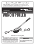
Auto-Darkening Welding Helmet
– Metal Head Design
Item 68782
Read this material before using this product.
Failure to do so can result in serious injury.
SAVE THIS MANUAL.
When unpacking, make sure that the product is intact and undamaged.
If any parts are missing or broken, please call 1-800-444-3353 as soon as possible.
Visit our website at: http://www.harborfreight.com
Copyright© 2011 by Harbor Freight Tools®. All rights reserved. No portion of this manual or any artwork contained herein may be reproduced in any shape
or form without the express written consent of Harbor Freight Tools. Diagrams within this manual may not be drawn proportionally. Due to continuing
improvements, actual product may differ slightly from the product described herein. Tools required for assembly and service may not be included.
Manual Revised 11i
Specifications
Description
Power Source
Operating Temp.
Resting Shade
Shade Range
UV/IR Protection
Lens Type
Viewing Area
Welding Protection
Types
Lens Switching
Speed (Clear to Dark)
Sensitivity Adjustment
Grinding Mode
Power ON / OFF
Shell Material
Storing Temperature
Features
Weight
Auto-Darkening Welding Helmet
Solar powered cells with battery assistance (not rechargeable)
23° to 131° F
Shade # 4
9 to 13
up to DIN 16 at all times
ANSI Z87.1-2003 approved
3.86” x 1.73”
For Processes including MIG/Flux welding, stick welding, TIG welding (10+
amps), plasma arc welding/cutting and air carbon cutting. Not for Laser Welding or
Oxyacetylene Welding/Cutting
1/25,000 second
High / Low
Transforms helmet to grinding shield without shade flickering
Fully Automatic
High Impact-Resistant Plastic Polyamide Nylon
-4° to 158° F
Ratcheting headband with replaceable padded sweatband, spare External cover lens,
2 independent arc sensors which reduce the risk of blocked sensors during out-ofposition welding, variable Shade Control Knob adjusts from #9 to #13 with a #4 resting
shade, Delay Control Switch, Sensitivity Control Switch
1.3 lb.
Save This Manual
Keep this manual for the safety warnings and precautions, assembly, operating, inspection,
maintenance and cleaning procedures. Write the product’s serial number in the back of the
manual near the assembly diagram (or month and year of purchase if product has no number).
Keep this manual and the receipt in a safe and dry place for future reference.
WARNING SYMBOLS AND DEFINITIONS
This is the safety alert symbol. It is used to alert you to potential personal injury hazards.
Obey all safety messages that follow this symbol to avoid possible injury or death.
Indicates a hazardous situation which, if not avoided,
will result in death or serious injury.
Indicates a hazardous situation which, if not avoided,
could result in death or serious injury.
Indicates a hazardous situation which, if not avoided,
could result in minor or moderate injury.
Addresses practices not related to personal injury.
Page 2
For technical questions, please call 1-800-444-3353.
SKU 68782
IMPORTANT SAFETY INFORMATION
WARNING
Read all safety warnings and instructions.
SEVERE PERSONAL INJURY and/or BLINDNESS
may occur if the user fails to follow these warnings
and/or fails to follow the operation instructions.
Save all warnings and instructions
for future reference.
The warnings, cautions, and instructions discussed
in this instruction manual cannot cover all possible
conditions and situations that may occur. It must be
understood by the operator that common sense and
caution are factors which cannot be built into this
product, but must be supplied by the operator.
1. Do not use the Welding Helmet if the lens is
cracked, if the lens or sensors are dirty, or if
the lens or front retaining frame is loose.
2. Keep work area clean.
Cluttered areas invite injuries.
3. Observe work area conditions. Do not use
welding helmets in damp or wet locations. Do not
expose to rain. Keep work area well lit. Do not use
in the presence of flammable gases or liquids.
4. Keep children away.
Do not let them handle this helmet.
5. Store idle equipment. When not in use,
helmets must be stored in a dry location.
Keep out of reach of children.
8. Replacement parts and accessories.
Do not use any replacement parts other than those
specified in this manual. Use of any other parts
can render the helmet ineffective, possibly causing
eye damage, and will void the warranty. Only use
accessories intended for use with this helmet.
9. Maintenance. For your safety, service
and maintenance should be performed
regularly only by a qualified technician.
10. This helmet provides protection for intended
purposes only. There are certain applications
for which this helmet was designed. Do not
modify this helmet and do not use this helmet
for a purpose for which it was not intended.
• The Welding Helmet is not suitable
for laser welding or oxyacetylene
welding/cutting processes.
• The Welding Helmet is not intended to protect
against explosive devices or corrosive liquids.
11. Use only at temperatures within the operating
range for your model as stated on the
specifications chart in this manual.
12. Maintain the helmet and lens correctly
to help ensure reliable protection.
• Clean filter’s surfaces regularly.
Keep sensors and solar cells clean using
a clean, lint-free tissue/cloth. Do not use any
solvents on filter’s screen or helmet components.
Protect filter from liquid and dirt contact.
Do not immerse the filter in water.
6. Dress properly. Protective gear is essential
to protect against welding rays, some
examples are: a leather welding apron, welding
sleeves, jeans without cuffs, work boots.
Wear restrictive hair covering to contain long hair.
• Should the Welding Helmet not darken
upon striking an arc, stop welding
immediately and have the helmet checked
by a qualified service technician.
7. Check for damaged parts. Before using any
helmet, any part that appears damaged should be
carefully checked to determine that it will operate
properly and perform its intended function. Check for
ill fitting parts that allow light to enter; any broken
parts or mounting fixtures; and any other condition
that may affect proper operation. Any part that is
damaged should be properly repaired or replaced
by a qualified technician. Do not use the helmet
if any switch does not operate properly.
• Do not make any modifications to either the
Filter Lens or the rest of the helmet,
other than those specified in this manual.
Unauthorized modifications will void the warranty
and expose the user to the risk of personal injury.
Do not open or tamper with the Filter Lens.
• Regularly replace the Front Lens Cover
if it becomes cracked, scratched,
pitted, or otherwise damaged.
13. Do not place the Filter Lens on a hot surface.
14. Read welder’s manual and follow all
instructions within for safe welding practices
SAVE THESE INSTRUCTIONS.
SKU 68782
For technical questions, please call 1-800-444-3353.
Page 3
Adjusting the Helmet
Features and Controls
1. Wear the helmet and set the headband size using
the knob on its back. Set it to keep the helmet
firmly on your head without it being too tight.
Time Delay and Sensitivity:
Delay Switch
Adjusts the speed the lens changes from dark to clear.
In FAST position: .25 - .45 seconds
In SLOW position: .65 - .80 seconds
2. To adjust the height of the Helmet, adjust the
strap that passes over the top of your head.
Push the locking nub out of the hole in the band,
adjust as needed, and push the locking nub
through the nearest hole.
3. Test the fit of the headband by lifting up and closing
down the helmet a few times while wearing it.
If the headband moves while tilting,
re-adjust it until it is stable.
SKU 68782
Sensitivity Adjustment Switch
Adjusts the amount of light needed
to activate the lens to darken.
Figure A: Controls Inside Helmet
Solar Cells: This Welding Helmet utilizes high
performance solar cells as power supply, and has two
built-in 3V lithium batteries as power backup. No change
of battery is needed. Under normal welding conditions,
users can expect a battery lifetime of more than 6 years.
Shade
Control Knob
4. Loosen both Adjustment Knobs to adjust
the distance between the helmet and
your face in the down position.
5. Slide the helmet nearer or further from your face.
It is important that your eyes are each the
same distance from the lens. Otherwise the
darkening effect may appear uneven.
6. Re-tighten both Adjustment Knobs.
Note: Numbers
correspond to
steps above.
Shell
4/6
4/6
2
Figure B: Shade Control Knob
Shade Control Knob: The shade control knob controls
the shade of the lens when it is in its dark state.
Turn the knob to the desired shade number.
The “Grind” setting disables the
auto‑darkening function, allowing the welding helmet to
be used for eye protection while grinding.
WARNING! The helmet will not provide adequate
eye protection for welding while in “Grind” mode.
Before Use
1. Remove the protective film from both sides
of the front lens (if not already done).
2. Adjust the Helmet so that it fits comfortably and the
user can easily see through the lens, as follows:
5
5
1
Figure C: Helmet Adjustment
Installing Magnifying Lens
compatible
Magnifying Lens
(not included)
Figure D:
Installing
Magnifying
“Cheater” Lens
Slide magnifying “cheater” lens into place INSIDE
the helmet under the four tabs, as shown above.
WARNING! Do not use a different Magnifying Lens
design or install lens outside welding helmet.
Page 4
For technical questions, please call 1-800-444-3353.
SKU 68782
Arc Current (Amperes)
Welding Process
10
20
5
15
40
80
30
60
9
10
Stick/Arc
Mild Steel MIG (argon shielded)
125
100
10
Aluminum MIG
9
10
11
11
10
TIG
11
12
11
Plasma Welding
10
11
12
11
13
14
13
14
14
13
14
14
12
13
12
13
500
12
13
10
9
450
350
12
12
11
8
300
275
13
12
Flux Core
Plasma Cutting
250
225
11
10
Mild Steel MIG (CO2 shielded)
175
150
14
13
14
Table A: Shade Guide
Operation Instructions
Troubleshooting
Read the ENTIRE IMPORTANT
SAFETY INFORMATION section at the
beginning of this manual including
all text under subheadings therein
before set up or use of this product.
1. Before each use, check the Front Lens Cover
to makes sure that it is clean, and that no dirt
is covering the two sensors on the front of the
Filter Cartridge. Also check the Inside Lens
Cover and the Front Lens Retaining Frame, and
make sure that they are secured in place.
2. Inspect all operating parts before each use for signs
of wear or damage. Any scratched, cracked, or
pitted parts should be replaced immediately before
using again to avoid severe personal injury.
3. Turn the shade knob to the correct shade
for the application as shown in Table A:
Shade Guide. If a selection of shades
are recommended for your application,
try the darkest setting (highest number) first.
4. Set the switches as explained on the facing page.
5. Adjust the headband so that the helmet is seated on
your head as low as possible and close to your face.
Adjust the helmet’s angle when in the lowered
position by turning the Adjustment Knobs.
WARNING! TO PREVENT SERIOUS INJURY
FROM ACCIDENTAL EXPOSURE:
Test the filter lens before welding.
While wearing the helmet, briefly strike an arc,
keeping your face and eyes turned slightly away,
and to one side. The lens should darken evenly
when not directly facing the arc. If it does not
darken properly, do not use the Welding Helmet.
1. Irregular Darkening or Dimming
Headband has been set unevenly
between the two sides of the helmet
(unequal distances from the eyes to filter’s lens).
2. Filter Lens Does Not Darken Or Flickers
a. Shade Control Knob set to “Grind”,
disabling auto‑darkening function
(turn shade knob to desired shade setting).
b. Front Lens Cover is soiled or damaged
(change the Lens Cover).
c. Sensor is soiled (clean sensor).
d. Welding current is too low
(turn Sensitivity Switch from low to high).
3. Slow Response
Operating temperature is too low
(do not use at temperatures below 23° F).
4. Poor Vision
a. Front/Inner Lens Cover and/or filter damaged/dirty
(change/clean it).
b. Insufficient ambient light
(increase work area ambient lighting).
c. Shade number is incorrectly set
(reset shade number).
5. Welding Helmet Slips
Headband is not adjusted properly (tighten).
WARNING: Stop using the Welding Helmet
IMMEDIATELY if any of the above‑mentioned
problems cannot be corrected.
6. After use, wipe with a clean cloth.
Store in a dry, safe place, away from children.
SKU 68782
For technical questions, please call 1-800-444-3353.
Page 5
Filter Lens Replacement
Maintenance
TO PREVENT SERIOUS INJURY
FROM HELMET FAILURE:
Do not use damaged equipment.
If damage or abnormal operation occurs,
have the problem corrected before further use.
1. BEFORE EACH USE, inspect the general
condition of the helmet. Check for loose
hardware, misalignment or binding of moving
parts, cracked or broken parts, damaged
electrical wiring, and any other condition
that may affect its safe operation.
1. Squeeze the Lens Holder Latches (8) inside
the Helmet at the base of the Lens Holder (5)
together and pull the bottom of the Lens Holder
towards the inside of the helmet. See Figure E.
2. Gently pull the Shade Control Knob (7) off
the side of the Helmet. See Figure G.
3. Remove Auto-darkening Filter (3) from Lens Holder:
a. Push up on top center of front of Lens Holder and,
b. lift top of Auto-darkening Filter out. See Figure F.
Auto-darkening
Filter (3)
2. Replace the Lens Cover(s) (2, 4) if they are cracked,
scratched, soiled, pitted or damaged in any way:
top of
b. lift
ut
Lens o
Filter
Front Lens Cover Replacement
1. Squeeze the Lens Holder Latches (8) inside
the Helmet at the base of the Lens Holder (5)
together and pull the bottom of the Lens Holder
towards the inside of the helmet. See Figure E.
Lens
Holder (5)
Inner Lens
Cover (4)
finger
notch
Lens
Holder (5)
h here
a. pus
Figure F: Removing Auto‑darkening Filter
WARNING! TO PREVENT SERIOUS INJURY
AND BLINDNESS:
Replace the Auto-darkening Filter ONLY with an
exact replacement. Other filters may not protect
properly from welding light, or may not fit helmet
closely enough to block all light at the edges.
4. Remove any protective film from
both sides of the new Lens.
5. Install new Filter Lens into the Lens Holder
and replace Lens Holder into Shell.
Lens Holder Latch (8)
Figure E: Lens Holder Latches
and Finger Notch
6. Place shade control wire up against side of Shell (1).
Attach Shade Control Knob (7) to post of
shade control wire. See Figure G.
shade
control
wire post
2. Remove Front Lens Cover (2) from Shell (1).
3. Remove any protective film from
both sides of the new Lens.
Shade
Control
Knob (7)
4. Assemble Front Lens Cover, Lens, and Lens Holder
into Shell the same way they were removed.
Inner Lens Cover Replacement
1. Remove the old Inner Lens Cover (4) by pulling
it up at the finger notch. See Figure E.
Auto-darkening
Filter (3)
Dial Marking
Panel (6)
Figure G: Shade control wire post
2. Remove any protective film from both
sides of the new Lens cover.
3. Line up the new Inner Lens Cover with the flanges
at the sides of the lens and snap it into place.
Page 6
For technical questions, please call 1-800-444-3353.
SKU 68782
PLEASE READ THE FOLLOWING CAREFULLY
THE MANUFACTURER AND/OR DISTRIBUTOR HAS PROVIDED THE PARTS LIST AND ASSEMBLY DIAGRAM
IN THIS MANUAL AS A REFERENCE TOOL ONLY. NEITHER THE MANUFACTURER OR DISTRIBUTOR
MAKES ANY REPRESENTATION OR WARRANTY OF ANY KIND TO THE BUYER THAT HE OR SHE IS
QUALIFIED TO MAKE ANY REPAIRS TO THE PRODUCT, OR THAT HE OR SHE IS QUALIFIED TO REPLACE
ANY PARTS OF THE PRODUCT. IN FACT, THE MANUFACTURER AND/OR DISTRIBUTOR EXPRESSLY
STATES THAT ALL REPAIRS AND PARTS REPLACEMENTS SHOULD BE UNDERTAKEN BY CERTIFIED AND
LICENSED TECHNICIANS, AND NOT BY THE BUYER. THE BUYER ASSUMES ALL RISK AND LIABILITY
ARISING OUT OF HIS OR HER REPAIRS TO THE ORIGINAL PRODUCT OR REPLACEMENT PARTS
THERETO, OR ARISING OUT OF HIS OR HER INSTALLATION OF REPLACEMENT PARTS THERETO.
Parts List and Assembly Diagram
Part
1
2
3
4
5
6
7
8
Description
Qty.
Shell
Front Lens Cover
Auto-darkening Filter
Inner Lens Cover
Lens Holder
Dial Marking Panel
Shade Control Knob
Lens Holder Latch
Part
1
1
1
1
1
1
1
2
9
10
11
12
13
14
15
16
Description
12
11
10
13
5
3
Qty.
Left Limitation Washer
Angle Adjustment Washer
Washer
Adjustment Knob
Right Limitation Washer
Screw
Adjustable Headband
Sweatband
4
1
2
2
2
1
2
1
1
14
14
15
9
16
2
10
11
12
1
8
6
7
Record Product’s Serial Number Here:
Note: If product has no serial number, record month and year of purchase instead.
Note: Some parts are listed and shown for illustration purposes only, and
are not available individually as replacement parts.
SKU 68782
For technical questions, please call 1-800-444-3353.
Page 7
90 Day Warranty
Harbor Freight Tools Co. makes every effort to assure that its products meet high quality and durability standards,
and warrants to the original purchaser that this product is free from defects in materials and workmanship for the
period of 90 days from the date of purchase. This warranty does not apply to damage due directly or indirectly,
to misuse, abuse, negligence or accidents, repairs or alterations outside our facilities, criminal activity, improper
installation, normal wear and tear, or to lack of maintenance. We shall in no event be liable for death, injuries
to persons or property, or for incidental, contingent, special or consequential damages arising from the use of
our product. Some states do not allow the exclusion or limitation of incidental or consequential damages, so the
above limitation of exclusion may not apply to you. THIS WARRANTY IS EXPRESSLY IN LIEU OF ALL OTHER
WARRANTIES, EXPRESS OR IMPLIED, INCLUDING THE WARRANTIES OF MERCHANTABILITY AND FITNESS.
To take advantage of this warranty, the product or part must be returned to us with transportation charges
prepaid. Proof of purchase date and an explanation of the complaint must accompany the merchandise.
If our inspection verifies the defect, we will either repair or replace the product at our election or we may
elect to refund the purchase price if we cannot readily and quickly provide you with a replacement. We will
return repaired products at our expense, but if we determine there is no defect, or that the defect resulted
from causes not within the scope of our warranty, then you must bear the cost of returning the product.
This warranty gives you specific legal rights and you may also have other rights which vary from state to state.
3491 Mission Oaks Blvd. • PO Box 6009 • Camarillo, CA 93011 • (800) 444-3353