1
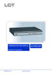
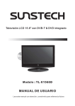
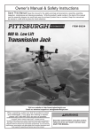
WARNING SYMBOLS AND DEFINITIONS
This is the safety alert symbol. It is used to alert you to
potential personal injury hazards. Obey all safety messages
that follow this symbol to avoid possible injury or death.
Indicates a hazardous situation which, if not avoided,
will result in death or serious injury.
Indicates a hazardous situation which, if not avoided,
could result in death or serious injury.
Indicates a hazardous situation which, if not avoided,
could result in minor or moderate injury.
Addresses practices not related to personal injury.
Important Safety Information
Read all safety warnings and instructions.
Failure to follow the warnings and instructions may result in
electric shock, fire and/or serious injury.
Save all warnings and instructions for future reference.
Installation Safety
1. Keep children and bystanders away
while installing the cameras. Distractions
can cause you to lose control.
2. Do not overreach when installing
this product. Keep proper footing
and balance at all times. This enables
better control in unexpected situations.
3. Wear ANSI-approved safety
goggles during installation.
4. This product is not a toy. Mount
it out of reach of children.
Operation Safety
1. Do not operate electrically powered
products in explosive atmospheres,
such as in the presence of flammable
liquids, gases, or dust. Electrically
powered products create sparks which
may ignite the dust or fumes.
2. The adapter must match the outlet.
Never modify the plug in any way.
Unmodified plugs and matching outlets
will reduce risk of electric shock.
Page 2
3. Do not expose the Power Adapter of
this product to rain or wet conditions.
Water entering the Power Adapter will
increase the risk of electric shock.
4. Do not abuse the Power Cord. Never
use the cord for unplugging the plug
from the outlet. Keep cord away
from heat, oil, sharp edges or moving
parts. Damaged or entangled cords
increase the risk of electric shock.
For technical questions, please call 1-800-444-3353.
Item 60565
5. WARNING: Handling the cord on this product
will expose you to lead, a chemical known
to the State of California to cause cancer,
and birth defects or other reproductive harm.
Wash hands after handling. (California
Health & Safety Code § 25249.5, et seq.)
6. The warnings, precautions, and instructions
discussed in this instruction manual cannot
cover all possible conditions and situations
that may occur. It must be understood by
the operator that common sense and caution
are factors which cannot be built into this
product, but must be supplied by the operator.
Service Safety
1. Product service must be performed
only by a qualified technician.
2. When servicing a product, use only
identical replacement parts.
4. Disconnect the AC/DC Power Adapter
from the power source before making any
adjustments, changing accessories, or
storing this product. Such preventive safety
measures reduce the risk of electric shock.
3. Maintain this product with care.
Keep this product clean. Do not use
a damaged product. Tag damaged
products “Do not use” until repaired.
5. Maintain labels and nameplates on the unit.
These carry important safety information.
If unreadable or missing, contact Harbor
Freight Tools for a replacement.
SAVE THESE INSTRUCTIONS.
Grounding
TO PREVENT ELECTRIC SHOCK AND DEATH FROM
INCORRECT GROUNDING WIRE CONNECTION:
Check with a qualified electrician if you are in doubt as to whether the outlet is
properly grounded. Do not modify the power cord plug provided with the system.
Never remove the grounding prong from the plug. Do not use the system if the power cord or
plug is damaged. If damaged, have it repaired by a service facility before use. If the plug will
not fit the outlet, have a proper outlet installed by a qualified electrician.
1. The included adapter does
not require grounding.
2. The adapter may be used in either
of the 120 volt outlets shown in the
preceding illustration. (See Figure A.)
Figure A: Outlets for 2-Prong Plug
Item 60565
For technical questions, please call 1-800-444-3353.
Page 3
Grounding (continued)
Extension Cords
Note: Do not use an extension
cord with this item’s adapter.
Symbology
Double Insulated
Canadian Standards
Association
Underwriters
Laboratories, Inc.
V
~
A
Volts
Alternating Current
Amperes
Specifications
MONITOR
120 V~ / 60 Hz Input
Power Adapter
12 VDC / 1 A Output
Screen Size
4.3" Diagonal
Color Configuration
R.G.B. Delta
Resolution
480 (H) x 272 (V)
Operating
14º to 122º F
Temperature
Operating Humidity
85% Maximum
Dimensions
5-1/4" L x 5-1/8" W x 1" H
Weight
0.5 lb.
CAMERA
Image Sensor
1/4" Color CMOS
Horizontal Resolution 380 TV lines
Effective Pixels
NTSC: 658 (H) x 492 (V)
Focal Length
6 mm
Minimum Illumination 1.0 lux without LED
Night Vision
Active (Illuminated) Infrared
Video Output
1.0 Vp-p75Ω
Signal/Noise Ratio
>48 dB
Camera Power Input DC 9 –12 V / 200 mA
Dimensions
2" L x 1-1/2" W x 2-1/2" H
Page 4
For technical questions, please call 1-800-444-3353.
Item 60565
Installation Instructions
Read the ENTIRE IMPORTANT SAFETY INFORMATION section
at the beginning of this manual including all text under
subheadings therein before set up or use of this product.
Components
AV Extension Cables
4.3" LCD Monitor
AC/DC Power
Adapter
AV Output
Cable
Cameras
AV Connection
Cables
Figure B
Item 60565
For technical questions, please call 1-800-444-3353.
Page 5
Installation Instructions (continued)
Controls
A
B
C
J
K
Figure C
D
E
F
G
H
I
A
Power Indicator
LED is lit red indicating the system has power
B
System On/
Off Indicator
LED is lit blue indicating the system is turned on
C
4.3" LCD
Monitor Screen
D
POWER
Power On/Off Switch
E
AUTO
For automatic continuous switching between the
two camera views at preset intervals
F
MANUAL
For manually switching between the two camera views
G
MUTE
Audio On/Off Switch
H
MENU
Used to scroll through and access Menus
I
< / > ˄ / ˅
Left/Right and Up/Down buttons used when
navigating in the Main Menu and Submenus
J
AV-OUT
Audio/Video Output Socket
K
DC 12V
12VDC Input Socket
Page 6
For technical questions, please call 1-800-444-3353.
Item 60565
Cable Connections
1. Connecting the Cameras to the Monitor:
a.Connect the Camera AV cables
(cable attached to the camera)
to the AV Extension cables.
b.Connect the AV Extension cables
to the AV Connection cables.
c.Insert the 4-pin plug end of the
AV Connection cables into the AV1 and
AV2 sockets on the back of the Monitor.
2. The signal from the Audio/Video Out socket
is the same as that on the Monitor display.
The signal can be sent to another monitor
(not included) using the AV Output cable.
3. Connect the power cord from the AC/DC
Power Adapter to the 12VDC Input Socket
on the Monitor. Plug the Power Adapter
into a 120 volt, grounded electrical outlet.
CAUTION! The Monitor and Power Adapter
MUST be used indoors in a clean, dry location.
AV Output Cable
Not included
AV Connection Cable
N
AV Extension Cable
Figure D
Item 60565
For technical questions, please call 1-800-444-3353.
Page 7
Camera Installation
IMPORTANT: Before mounting the cameras, test the system by connecting all the cables and testing
to ensure the system is working properly. Test the cameras for the best location before installing.
1. When planning the mounting location and
angle of the Cameras, consider the following:
a.Do not mount the Cameras in
bright or direct sunlight.
b.At night windows can reflect back
into the Camera, interfering with the
image. Test the Cameras in their
intended location before mounting.
c.Choose locations high enough so
that the Cameras are out of reach of
children and others who might tamper
with the units, but still cover the
desired viewing areas adequately.
d.Take into consideration the length of
the cables and the need to place the
Monitor in a safe, dry location. Do
not expose the Monitor to weather.
2. Route the AC/DC Adapter power cord
and all cabling along a safe route without
creating a tripping hazard or exposing the
cord and cables to possible damage.
3. Mount the Cameras to the chosen
locations as follows:
a.Place the Bracket Base against the
mounting surface and use mounting
holes in the base as a template to mark
the three points for drilling pilot holes.
WARNING! Verify that installation surface
has no hidden utility lines or other wiring
before drilling or driving screws.
b.Drill the pilot holes.
c.Mount the Cameras using three appropriate
fasteners through the three holes in
the Bracket Base of each Camera.
d.After the Cameras are mounted,
run the cables to the Monitor.
e.Adjust the Cameras to cover
the desired areas.
f. Once Cameras are installed, plug
the cables into the Monitor.
Operating Instructions
Read the ENTIRE IMPORTANT SAFETY INFORMATION section
at the beginning of this manual including all text under
subheadings therein before set up or use of this product.
General Operating Instructions
1. Press the POWER switch on the Monitor
to turn on the system. The camera’s
view should appear on the screen.
2. Press the AUTO button to select automatic
switching from one camera view to the other.
3. Press the MANUAL button to manually select
between one camera view and the other.
4. Press the MUTE button to
turn the audio on or off.
Page 8
5. Use the MENU button and Left/Right (< / >) or
Up/Down (˄ / ˅) buttons to make adjustments
or change settings following guidelines in
the MENU Settings section on page 9.
6. The system will operate continuously (day
and night) while the AC/DC Power Adapter
is plugged in and the system is turned on.
7. When not using the system, unplug the
Power Adapter from the electrical outlet.
For technical questions, please call 1-800-444-3353.
Item 60565
MENU Settings
1. Press the POWER switch to turn on
the system. Press the MENU button to
scroll through and access menus. (See
Figure C on page 6 for control layout).
2. To adjust picture quality:
a.Select the PICTURE menu
using the MENU button.
b.Use the Up (˄) or Down (˅) buttons to
select BRIGHT, CONTRAST, or COLOR.
c.Use the Left (<) or Right (>) buttons
to adjust to the desired settings.
5. To select system video standard:
a.Select the SYSTEM menu
using the MENU button.
b.Use the Left (<) or Right (>) buttons to
select AUTO, PAL, NTSC, or SECAM.
6. To apply preset timer options:
a.Select the PRESET menu
using the MENU button.
b.Use the Up (˄) or Down (˅) buttons to select
SLEEP, TIME, OFF-TIME, or ON-TIME.
3. To adjust volume:
a.Select the VOLUME menu
using the MENU button.
b.Use the Left (<) or Right (>) buttons to
adjust volume to the desired level.
4. To adjust time interval in AUTO switch mode:
a.Select the OPTION menu
using the MENU button.
b.Select the desired setting by using
the Left (<) or Right (>) buttons to
adjust the time interval from 5 to 99
seconds for automatic switching from
one camera view to the other.
c.Use the Left (<) or Right (>) buttons
to adjust to the desired settings.
Note: If power to the Monitor is cut off or the
system is shut off any settings previously
entered in the PRESET menu will be lost and
the information will need to be re-entered.
Inspection, Maintenance, and Cleaning
Procedures not specifically explained in this manual must
be performed only by a qualified technician.
TO PREVENT SERIOUS INJURY FROM ELECTRIC SHOCK:
Unplug the Power Adapter from its electrical outlet
before inspection, maintenance, or cleaning.
1. BEFORE EACH USE, inspect the general
condition of the Cameras and Monitor. Check
for loose screws, misalignment or binding
of moving parts, cracked or broken parts,
damaged electrical wiring, loose connections,
and any other condition that may affect safe
operation. If a problem occurs, have the
problem corrected before further use.
Do not use damaged equipment.
Item 60565
2. WEEKLY: Wipe off Camera Lenses with
a soft, clean, moist cloth. Then dry. Clean
Monitor to prevent dust from accumulating on
the screen. Use a dry cloth during cleaning.
For technical questions, please call 1-800-444-3353.
Page 9
Parts Lists and Assembly Diagrams
Monitor Parts List and Assembly Diagram
Part
1
2
3
4
5
Description
Transparent Lens
4.3" LCD Screen
Front Case
Direction Key
Menu Button
Qty
1
1
1
1
1
Part
6
7
8
9
10
Description
Function Button Module
PCB
Rear Case
Support
AC/DC Adapter
Qty
1
1
1
1
1
Record Product’s Serial Number Here:
Note: If product has no serial number, record month and year of purchase instead.
Note: Some parts are listed and shown for illustration purposes only,
and are not available individually as replacement parts.
Page 10
For technical questions, please call 1-800-444-3353.
Item 60565
Camera Parts List and Assembly Diagram
Part
1A
2A
3A
4A
5A
6A
7A
8A
9A
10A
11A
12A
13A
14A
15A
16A
17A
18A
Description
Cap
Cap Screw
Lens
Screw
Front Panel
Screw
LED
PCB & IC
AV Cable
Back Panel
Screw
Bracket Crown
Bracket Rocker
Bracket Rocker Base
Bracket Spring
Bracket Base
Bracket Base Foam Cover
Screw
Qty
1
2
1
1
1
1
1
1
1
1
2
1
1
1
1
1
1
2
1A
2A
3A
4A
5A
6A
7A
8A
9A
10A
11A
12A
13A
14A
15A
16A
17A
18A
Item 60565
For technical questions, please call 1-800-444-3353.
Page 11
PLEASE READ THE FOLLOWING CAREFULLY
THE MANUFACTURER AND/OR DISTRIBUTOR HAS PROVIDED THE PARTS LIST AND
ASSEMBLY DIAGRAM IN THIS MANUAL AS A REFERENCE TOOL ONLY. NEITHER THE
MANUFACTURER OR DISTRIBUTOR MAKES ANY REPRESENTATION OR WARRANTY
OF ANY KIND TO THE BUYER THAT HE OR SHE IS QUALIFIED TO MAKE ANY REPAIRS
TO THE PRODUCT, OR THAT HE OR SHE IS QUALIFIED TO REPLACE ANY PARTS OF
THE PRODUCT. IN FACT, THE MANUFACTURER AND/OR DISTRIBUTOR EXPRESSLY
STATES THAT ALL REPAIRS AND PARTS REPLACEMENTS SHOULD BE UNDERTAKEN
BY CERTIFIED AND LICENSED TECHNICIANS, AND NOT BY THE BUYER. THE
BUYER ASSUMES ALL RISK AND LIABILITY ARISING OUT OF HIS OR HER REPAIRS
TO THE ORIGINAL PRODUCT OR REPLACEMENT PARTS THERETO, OR ARISING
OUT OF HIS OR HER INSTALLATION OF REPLACEMENT PARTS THERETO.
Limited 90 Day Warranty
Harbor Freight Tools Co. makes every effort to assure that its products meet high quality
and durability standards, and warrants to the original purchaser that this product is free from
defects in materials and workmanship for the period of 90 days from the date of purchase. This
warranty does not apply to damage due directly or indirectly, to misuse, abuse, negligence or
accidents, repairs or alterations outside our facilities, criminal activity, improper installation,
normal wear and tear, or to lack of maintenance. We shall in no event be liable for death,
injuries to persons or property, or for incidental, contingent, special or consequential damages
arising from the use of our product. Some states do not allow the exclusion or limitation of
incidental or consequential damages, so the above limitation of exclusion may not apply to
you. THIS WARRANTY IS EXPRESSLY IN LIEU OF ALL OTHER WARRANTIES, EXPRESS
OR IMPLIED, INCLUDING THE WARRANTIES OF MERCHANTABILITY AND FITNESS.
To take advantage of this warranty, the product or part must be returned to us with
transportation charges prepaid. Proof of purchase date and an explanation of the complaint
must accompany the merchandise. If our inspection verifies the defect, we will either repair or
replace the product at our election or we may elect to refund the purchase price if we cannot
readily and quickly provide you with a replacement. We will return repaired products at our
expense, but if we determine there is no defect, or that the defect resulted from causes not
within the scope of our warranty, then you must bear the cost of returning the product.
This warranty gives you specific legal rights and you may also
have other rights which vary from state to state.
3491 Mission Oaks Blvd. • PO Box 6009 • Camarillo, CA 93011 • (800) 444-3353