1
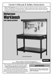
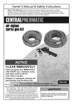
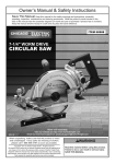
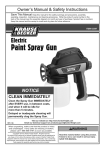
Table of Contents
Safetye��������������������������������������������������������� 3
Specifications.............................................. 6
Setup........................................................... 7
Operationa��������������������������������������������������� 12
Maintenancei���������������������������������������������� 13
Parts List and Diagram............................... 14
Warranty..................................................... 16
WARNING SYMBOLS AND DEFINITIONS
This is the safety alert symbol. It is used to alert you to potential personal injury hazards.
Obey all safety messages that follow this symbol to avoid possible injury or death.
Indicates a hazardous situation which, if not avoided,
will result in death or serious injury.
Indicates a hazardous situation which, if not avoided,
could result in death or serious injury.
Indicates a hazardous situation which, if not avoided,
could result in minor or moderate injury.
Addresses practices not related to personal injury.
Page 2
For technical questions, please call 1-800-444-3353.
Item 60739
IMPORTANT SAFETY INFORMATION
General Tool Safety Warnings
Read all safety warnings and instructions.
Failure to follow the warnings and instructions may result in electric shock, fire and/or serious injury.
Save all warnings and instructions for future reference.
1. KEEP GUARDS IN PLACE and in working order.
2. REMOVE ADJUSTING KEYS AND WRENCHES.
Form habit of checking to see that keys and adjusting
wrenches are removed from tool before turning it on.
3. KEEP WORK AREA CLEAN.
Cluttered areas and benches invite accidents.
4. DON’T USE IN DANGEROUS ENVIRONMENT.
Don’t use power tools in damp or wet locations,
or expose them to rain. Keep work area well lighted.
5. KEEP CHILDREN AWAY. All visitors should
be kept safe distance from work area.
6. MAKE WORKSHOP KID PROOF with padlocks,
master switches, or by removing starter keys.
7. USE RIGHT TOOL. Don’t force tool or attachment
to do a job for which it was not designed.
Table A: RECOMMENDED MINIMUM WIRE GAUGE
FOR EXTENSION CORDS
(120 VOLT)
NAMEPLATE
AMPERES
(at full load)
EXTENSION CORD
LENGTH
25′
50′ 100′ 150′
0–6
18
16
16
14
6.1 – 10
18
16
14
12
10.1 – 12
16
16
14
12
12.1 – 16
14
12
Do not use.
8. USE PROPER EXTENSION CORD. Make sure your
extension cord is in good condition. When using
an extension cord, be sure to use one heavy
enough to carry the current your product will draw.
An undersized cord will cause a drop in line
voltage resulting in loss of power and overheating.
Table A shows the correct size to use depending
on cord length and nameplate ampere rating.
If in doubt, use the next heavier gauge.
The smaller the gauge number, the heavier the cord.
9. WEAR PROPER APPAREL. Do not wear
loose clothing, neckties, rings, bracelets, or other
jewelry which may get caught in moving parts.
Nonslip footwear is recommended.
Wear protective hair covering to contain long hair.
10. ALWAYS USE SAFETY GLASSES. Also use
face or dust mask if cutting operation is dusty.
Everyday eyeglasses only have impact resistant
lenses, they are NOT safety glasses.
11. MAINTAIN TOOLS WITH CARE. Keep tools clean
for best and safest performance. Follow instructions
for lubricating and changing accessories.
12. DISCONNECT TOOLS before servicing.
13. REDUCE THE RISK OF UNINTENTIONAL
STARTING. Make sure switch is in
off position before plugging in.
14. USE RECOMMENDED ACCESSORIES.
Consult the owner’s manual for recommended
accessories. The use of improper accessories
may cause risk of injury to persons.
15. CHECK DAMAGED PARTS. Before further use
of the tool, a guard or other part that is damaged
should be carefully checked to determine that
it will operate properly and perform its intended
function – check for alignment of moving parts,
binding of moving parts, breakage of parts,
mounting, and any other conditions that may
affect its operation. A guard or other part that is
damaged should be properly repaired or replaced.
16. NEVER LEAVE TOOL RUNNING UNATTENDED.
TURN POWER OFF. Don’t leave tool
until it comes to a complete stop.
Item 60739
For technical questions, please call 1-800-444-3353.
Page 3
Grounding Instructions
TO PREVENT ELECTRIC SHOCK AND DEATH FROM INCORRECT GROUNDING WIRE CONNECTION
READ AND FOLLOW THESE INSTRUCTIONS:
110-120 V~ Grounded Tools: Tools with Three Prong Plugs
1. In the event of a malfunction or breakdown,
grounding provides a path of least resistance for
electric current to reduce the risk of electric shock.
This tool is equipped with an electric cord having an
equipment-grounding conductor and a grounding
plug. The plug must be plugged into a matching
outlet that is properly installed and grounded in
accordance with all local codes and ordinances.
2. Do not modify the plug provided – if it will
not fit the outlet, have the proper outlet
installed by a qualified electrician.
3. Improper connection of the equipment-grounding
conductor can result in a risk of electric shock.
The conductor with insulation having an outer
surface that is green with or without yellow
stripes is the equipment-grounding conductor.
If repair or replacement of the electric cord or
plug is necessary, do not connect the equipmentgrounding conductor to a live terminal.
4. Check with a qualified electrician or service
personnel if the grounding instructions are
not completely understood, or if in doubt as
to whether the tool is properly grounded.
6. Repair or replace damaged or worn cord immediately.
Grounding
Pin
125 V~ 3-Prong Plug and Outlet
(for up to 125 V~ and up to 15 A)
7. This tool is intended for use on a circuit that has
an outlet that looks like the one illustrated above
in 125 V~ 3-Prong Plug and Outlet. The tool has
a grounding plug that looks like the plug illustrated
above in 125 V~ 3-Prong Plug and Outlet.
8. The outlet must be properly installed and grounded
in accordance with all codes and ordinances.
9. Do not use an adapter to connect
this tool to a different outlet.
5. Use only 3-wire extension cords that
have 3-prong grounding plugs and 3-pole
receptacles that accept the tool’s plug.
Page 4
For technical questions, please call 1-800-444-3353.
Item 60739
Dust Reclaimer Safety Warnings
For Your Own Safety Read Instruction
Manual Before Operating
1. Wear eye protection.
2. Do not use with any openings blocked.
Keep openings clear of anything that may
limit air flow or hinder motor operation.
3. Do not use the Reclaimer without its
Filter (18) in place. Before each use,
make sure the Filter is not clogged.
4. This product is designed only to pick up dry debris.
Do not use the Dust Reclaimer to pick up
water (or any other liquid) from the floor or
containers such as sinks, tubs, barrels, etc.
5. When mounting the Dust Reclaimer to a wall surface,
make sure the wall and the mounting hardware
used (not included) are capable of supporting the
weight of the Dust Reclaimer and its contents.
6. Prior to drilling mounting holes in a wall surface,
check to make sure there are no hidden electrical
cables, gas or plumbing pipes in the drilling path.
7. Do not use for abrasives containing crystalline silica.
Silica containing abrasives have been linked to
severe respiratory disease such as silicosis.
Use proper abrasives such as aluminum oxide,
glass bead, or walnut shell.
8. DO NOT OPERATE WITH ANY GUARD
DISABLED, DAMAGED, OR REMOVED.
9. The use of accessories or attachments not
recommended by the manufacturer may
result in a risk of injury to persons.
10. When servicing use only identical replacement parts.
11. Only use safety equipment that has been approved
by an appropriate standards agency. Unapproved
safety equipment may not provide adequate
protection. Eye protection must be ANSI-approved
and breathing protection must be NIOSH-approved
for the specific hazards in the work area.
12. Stay alert, watch what you are doing and use
common sense when operating a power tool.
Do not use a power tool while you are tired or
under the influence of drugs, alcohol or medication.
A moment of inattention while operating power
tools may result in serious personal injury.
13. Industrial applications must follow OSHA guidelines.
14. Maintain labels and nameplates on the tool.
These carry important safety information.
If unreadable or missing, contact
Harbor Freight Tools for a replacement.
15. Avoid unintentional starting.
Prepare to begin work before turning on the tool.
16. People with pacemakers should consult their
physician(s) before use. Electromagnetic fields in
close proximity to heart pacemaker could cause
pacemaker interference or pacemaker failure.
17. WARNING: Some dust created by power
sanding, sawing, grinding, drilling, and other
construction activities, contains chemicals
known [to the State of California] to cause
cancer, birth defects or other reproductive harm.
Some examples of these chemicals are:
• Lead from lead-based paints
• Crystalline silica from bricks and cement or other
masonry products
• Arsenic and chromium from
chemically treated lumber
Your risk from these exposures varies,
depending on how often you do this type of work.
To reduce your exposure to these chemicals:
work in a well ventilated area, and
work with approved safety equipment, such
as those dust masks that are specially
designed to filter out microscopic particles.
(California Health & Safety Code § 25249.5, et seq.)
18. WARNING: Handling the cord on this product will
expose you to lead, a chemical known to the State
of California to cause cancer, and birth defects or
other reproductive harm. Wash hands after handling.
(California Health & Safety Code § 25249.5, et seq.)
19. The warnings, precautions, and instructions
discussed in this instruction manual cannot cover all
possible conditions and situations that may occur.
It must be understood by the operator that
common sense and caution are factors
which cannot be built into this product, but
must be supplied by the operator.
SAVE THESE INSTRUCTIONS.
Item 60739
For technical questions, please call 1-800-444-3353.
Page 5
Specifications
Page 6
Electrical Rating
120V~ / 60Hz / 12A
Motor No Load Speed
18,900 RPM
Product Compatibility
For use with Item 60738 Industrial Blast Cabinet
Capacity
Approximately 1-3/4 Gallons
Hose Size
2″ Diameter x 3 Ft. Long
For technical questions, please call 1-800-444-3353.
Item 60739
Assembly
Read the ENTIRE IMPORTANT SAFETY INFORMATION section at the beginning of this
manual including all text under subheadings therein before set up or use of this product.
TO PREVENT SERIOUS INJURY FROM ACCIDENTAL OPERATION:
Turn the Power Switch of the tool off and unplug the tool from its electrical
outlet before performing any procedure in this section.
Note: For additional information regarding the parts listed in the following pages,
refer to the Assembly Diagram near the end of this manual.
The Dust Reclaimer Kit can be attached to a wall surface (see instructions below), or it
can be mounted to the back of 60738 Industrial Blast Cabinet (see page 10).
How To Install The Dust Reclaimer To A Wall
IMPORTANT: The Wire Mesh Reinforced Hose (16B) supplied with the Dust Reclaimer is 3 feet long.
When determining a permanent location for the 60738 Blast Cabinet, make sure the Blast Cabinet is within
3 feet of the wall surface on which the Dust Reclaimer will be mounted. (See Figure 7, page 13).
NOTE: You may wish to connect a longer Wire Mesh Reinforced Hose (not included) between the Blast Cabinet
and Dust Reclaimer. If so, make sure the longer Hose has a 2″ diameter, and use a proper extension cord
to connect the Power Cord Plug (12) of the Dust Reclaimer to the Lamp Housing on the Blast Cabinet.
1. Open the right side door of the blast cabinet.
Remove the four screws on the exhaust board.
Take out the exhaust board (see Figure A).
Bolts (47)
Hose
Connector
(48)
Exhaust
Board
Figure B
Figure A
3. Re-install the Exhaust Board over the
Hose Connector (48) (see Figure A).
2. Install the Hose Connector (48) using four
M5x12 bolts (47) as shown in Figure B below.
Item 60739
For technical questions, please call 1-800-444-3353.
Page 7
4. Use the pattern in Figure C as a reference, or
hold the assembled Dust Reclaimer against the
wall where you intend to mount it, and mark the
drill hole positions through the mounting holes.
5. Drill holes in the wall to except the Wall Anchors (33).
Use a concrete drill bit that is 5/16″ diameter.
CAUTION! When mounting the Dust Reclaimer
to a wall surface, make sure that the wall and the
mounting hardware used are capable of supporting
the weight of the Dust Reclaimer and its contents.
Prior to drilling mounting holes in a wall surface,
check to make sure there are no hidden electrical
cables, gas or plumbing pipes in the drilling path.
NOTE: The Wall Anchors (33) are intended
for concrete walls. If you are attaching the
Dust Reclaimer Kit to drywall or wood you will
need different fasteners (not included).
1.57″
9.73″
1.57″
9.52″
9.52″
Figure C
Page 8
For technical questions, please call 1-800-444-3353.
Item 60739
6. Tap the Wall Anchors (33) into the wall using
a hammer. They will expand inside the wall when
you thread a nut onto them. See Figure D below.
7. Attach the dust reclaimer to the wall using
Washers (35), Spring Washers (36) and Nuts (46).
See Figure E below.
wal
l
Wall
Anchor
(33)
Washer
(35)
Figure D
Spring
Washer (36)
Nut (34)
Figure E
8. Attach the blast cabinet to the Dust Reclaimer
as shown in Figure F, then firmly tighten
up the Hose Clamps (15).
Hose
Connector
(48)
Hose
Clamp
(15)
Hose
(16B)
Hose
Clamp
(15)
Figure F
Item 60739
For technical questions, please call 1-800-444-3353.
Page 9
How To Install The Dust Reclaimer To A Blast Cabinet (60738)
1. Open the right side door of the blast cabinet.
Remove the four screws on the exhaust board.
Take out the Exhaust Board (see Figure G).
4. Assemble the two Support Brackets (32) to the
Housing (22A) using Bolts (28), Spring Washers (29),
Washers (30), and Nuts (31). Do not tighten the
Nuts (31) completely at this point. See Figure I.
5. Place the Support Brackets (32) on a flat
surface. Adjust the position of the support
brackets and the Dust Reclaimer hose nozzle
until it looks like it does in Figure I.
6. Make sure the Support Brackets are parallel
with the dust collector hose nozzle. After
ensuring the support brackets center line is
in line with that of the dust collector hose,
firmly tighten the Nuts (31). See Figure I.
Bolt (28)
Washer (30) x2
Spring Washer (29)
and Nut (31)
Exhaust
Board
Figure G
Support
Bracket (32)
Housing
(22A)
2. Install the Hose Connector (48) using
four Bolts (47) as shown in Figure H.
Bolts (47)
Support
Bracket (32)
Figure I
Hose
Connector
(48)
Figure H
3. Re-install the Exhaust Board as shown in Figure G.
Page 10
For technical questions, please call 1-800-444-3353.
Item 60739
7. There will be bolts and nuts already in
the holes where the Dust Reclaimer
will be attached to the Blast Cabinet.
Remove the bolts and nuts. See Figure J.
8. Attach the Dust Reclaimer to Blast Cabinet using the
Bolts (51), Flat Washers (44), Spring Washers (45)
and Nuts (46). Parts 45 and 48 attach to the
bolts from inside the cabinet. See Figure K.
Figure J
Hose
Connector
(48)
Hose
(16A)
Hose
Clamp
(15)
Hose
Clamp
(15)
Figure K
Item 60739
For technical questions, please call 1-800-444-3353.
Page 11
Operating Instructions
Read the ENTIRE IMPORTANT SAFETY INFORMATION section at the beginning of this
manual including all text under subheadings therein before set up or use of this product.
TO PREVENT SERIOUS INJURY FROM ACCIDENTAL OPERATION:
Turn the Power Switch of the tool off and unplug the tool from its electrical
outlet before performing any procedure in this section.
PREVENT SERIOUS INJURY:
DO NOT OPERATE WITH ANY GUARD DISABLED, DAMAGED, OR REMOVED.
1. Make sure the Dust Collector Cap is
closed and latched. Then, turn on the Dust
Reclaimer using the Power Switch.
2. The Dust Reclaimer will immediately
activate, drawing airborne particles out of
the Blast Cabinet and into the Filter and
Dust Housing of the Dust Reclaimer.
3. To prevent accidents, turn off the tool and
disconnect its power supply after use.
Page 12
For technical questions, please call 1-800-444-3353.
Item 60739
Maintenance and Servicing
Procedures not specifically explained in this manual must
be performed only by a qualified technician.
TO PREVENT SERIOUS INJURY FROM ACCIDENTAL OPERATION:
Turn the Power Switch of the tool off and unplug the tool from its electrical
outlet before performing any procedure in this section.
TO PREVENT SERIOUS INJURY FROM TOOL FAILURE:
Do not use damaged equipment. If abnormal noise or vibration
occurs, have the problem corrected before further use.
1. BEFORE EACH USE, inspect the general
condition of the tool. Check for:
c. Push in and out on the Pull Rod (24) several
times to help shake out any remaining dust
and debris from the Dust Reclaimer.
• loose hardware,
d. Close the Dust Collector Cap (26),
and refasten the Latch (27).
• misalignment or binding of moving parts,
• cracked or broken parts,
• damaged electrical wiring,
• plugged hose or suction port, and
• any other condition that may
affect its safe operation.
4. Periodically, remove the Filter (18) and use
compressed air to blow out the dust and debris
from the Filter to keep the Dust Reclaimer working
efficiently. Replace the Filter as needed:
a. Unplug the Power Cord from its electrical outlet.
b. Remove the Radiating Guard (1) from
the top of the Dust Reclaimer.
2. AFTER USE, wipe external surfaces
of the tool with clean cloth.
3. Inadequate Blast Cabinet ventilation will result in
reduced cleaning power as well as diminished view
of the work in progress. Empty the Dust Reclaimer
after every 20 to 30 minutes of Blast Cabinet use
(more often in more dusty conditions):
a. Unplug the Power Cord from its electrical outlet.
b. Release the Latch (27), and open the
Dust Collector Cap (26) at the bottom of the
Dust Reclaimer. Then, allow the dust and debris
to pour out into a proper waste container.
c. Remove the Filter (18), and clean
with compressed air.
d. Replace the Filter (18) and Radiating Guard (1).
5.
WARNING! If the supply cord of this
power tool is damaged, it must be replaced
only by a qualified service technician.
Troubleshooting
Problem
Possible Solutions
Dust Reclaimer
does not
turn on.
1. Make sure the Power Switch (25) on is in its “ON” position.
2. Make sure the Power Cord Plug of the Dust Reclaimer is properly
connected to a working, 120 volt, grounded, electrical outlet.
3. Have a qualified service technician check out the Dust Reclaimer and Blast Cabinet.
Poor visibility
within the Blast
Cabinet.
1. Check to make sure Dust Reclaimer is on.
2. Dust Reclaimer is filled. Empty and clean out Dust Reclaimer.
3. Filter in Dust Reclaimer needs to be cleaned or replaced.
4. Check to make sure there is no clogging in the Wire Mesh Reinforced Hose.
5. Have a qualified service technician check out the Dust Reclaimer and Blast Cabinet.
Follow all safety precautions whenever diagnosing or servicing the tool.
Disconnect power supply before service.
Item 60739
For technical questions, please call 1-800-444-3353.
Page 13
Parts List and Diagram
PLEASE READ THE FOLLOWING CAREFULLY
THE MANUFACTURER AND/OR DISTRIBUTOR HAS PROVIDED THE PARTS LIST AND ASSEMBLY DIAGRAM
IN THIS MANUAL AS A REFERENCE TOOL ONLY. NEITHER THE MANUFACTURER OR DISTRIBUTOR
MAKES ANY REPRESENTATION OR WARRANTY OF ANY KIND TO THE BUYER THAT HE OR SHE IS
QUALIFIED TO MAKE ANY REPAIRS TO THE PRODUCT, OR THAT HE OR SHE IS QUALIFIED TO REPLACE
ANY PARTS OF THE PRODUCT. IN FACT, THE MANUFACTURER AND/OR DISTRIBUTOR EXPRESSLY
STATES THAT ALL REPAIRS AND PARTS REPLACEMENTS SHOULD BE UNDERTAKEN BY CERTIFIED AND
LICENSED TECHNICIANS, AND NOT BY THE BUYER. THE BUYER ASSUMES ALL RISK AND LIABILITY
ARISING OUT OF HIS OR HER REPAIRS TO THE ORIGINAL PRODUCT OR REPLACEMENT PARTS
THERETO, OR ARISING OUT OF HIS OR HER INSTALLATION OF REPLACEMENT PARTS THERETO.
Parts List
Part
1
2
3
4
5
6
7
8
9
10
11
12
13
14
15
16A
16B
17
18
19
20
21
Description
Radiating Guard
Screw (M6x12)
Motor
Screw (M5x15)
Nut (M5)
Spring Washer
Motor Fixed Plate
Hex Nut (M6)
Hex Nut
Double Head Retaining Bolt
Retaining Nut
Power Cord
Protective Guard
Bolt (M5x20)
2″ Hose Clamp
Wire Mesh Reinforced Hose
Wire Mesh Reinforced Hose
Mounting Base
Filter
Double Head Screw Rod
Flat Washer
Wing Nut (M6)
Qty
1
4
1
4
4
4
4
3
1
1
1
1
1
4
2
1
1
1
1
1
1
1
Part
22A
23
24
25
26
27
28
29
30
31
32
33
34
35
36
44
45
46
47
48
51
Description
Housing
Spring
Pull Rod
Power Switch
Dust Collector Cap
Latch
Bolt (M8x20)
Spring Washer
Flat Washer
Nut (M8)
Support Brackets
Wall Anchor
Nut
Flat Washer
Spring Washer
Flat Washer
Spring Washer
Nut M8
M5 x12 Bolt
Hose Connector
M8 x20 Bolt
Qty
1
1
1
1
1
3
6
6
12
6
2
8
8
8
8
8
8
8
4
1
8
Record Product’s Serial Number Here:
Note: If product has no serial number, record month and year of purchase instead.
Note: Some parts are listed and shown for illustration purposes only,
and are not available individually as replacement parts.
Page 14
For technical questions, please call 1-800-444-3353.
Item 60739
Assembly Diagram
46 45
12
51
44
25
8
14
13
25
48
47
2
6
1
3
4
5
7
11 10 9
15
16A
8
16B
22
15
27
27
27
17 8
28
29
30
30
31
23 24
26
18
19
20
21
32
35
36
34
33
wall
Page 15
For technical questions, please call 1-800-444-3353.
Item 60739
Limited 90 Day Warranty
Harbor Freight Tools Co. makes every effort to assure that its products meet high quality and durability standards,
and warrants to the original purchaser that this product is free from defects in materials and workmanship for the
period of 90 days from the date of purchase. This warranty does not apply to damage due directly or indirectly,
to misuse, abuse, negligence or accidents, repairs or alterations outside our facilities, criminal activity, improper
installation, normal wear and tear, or to lack of maintenance. We shall in no event be liable for death, injuries
to persons or property, or for incidental, contingent, special or consequential damages arising from the use of
our product. Some states do not allow the exclusion or limitation of incidental or consequential damages, so the
above limitation of exclusion may not apply to you. THIS WARRANTY IS EXPRESSLY IN LIEU OF ALL OTHER
WARRANTIES, EXPRESS OR IMPLIED, INCLUDING THE WARRANTIES OF MERCHANTABILITY AND FITNESS.
To take advantage of this warranty, the product or part must be returned to us with transportation charges
prepaid. Proof of purchase date and an explanation of the complaint must accompany the merchandise.
If our inspection verifies the defect, we will either repair or replace the product at our election or we may
elect to refund the purchase price if we cannot readily and quickly provide you with a replacement. We will
return repaired products at our expense, but if we determine there is no defect, or that the defect resulted
from causes not within the scope of our warranty, then you must bear the cost of returning the product.
This warranty gives you specific legal rights and you may also have other rights which vary from state to state.
3491 Mission Oaks Blvd. • PO Box 6009 • Camarillo, CA 93011 • (800) 444-3353