1
Safety
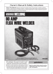
90 AMP FLUX WIRE welder
Read this material before using this product.
Failure to do so can result in serious injury.
Save this manual.
Copyright© 2008 by Harbor Freight Tools®. All rights reserved. No portion of this manual or any artwork
contained herein may be reproduced in any shape or form without the express written consent of
Harbor Freight Tools. Diagrams within this manual may not be drawn proportionally. Due to continuing
improvements, actual product may differ slightly from the product described herein. Tools required for
assembly and service may not be included.
For technical questions or replacement parts, please call 1-800-444-3353.
Manual Revised 10d
Service
Visit our website at: http://www.harborfreight.com
Welding Tips
Basic Welding
Set up and Operating Instructions
Setup
Model 98871
NOTICE is used to
address practices not
related to personal injury.
Save This Manual
Safety
Keep this manual for the safety warnings
and precautions, assembly, operating,
inspection, maintenance and cleaning
procedures. Write the product’s serial number
in the back of the manual near the assembly
diagram (or month and year of purchase if
product has no number). Keep this manual
and the receipt in a safe and dry place for
future reference.
CAUTION, without the
safety alert symbol, is
used to address practices not
related to personal injury.
General Safety Warnings
Setup
WARNING Read all safety warnings
and instructions. Failure to follow the
warnings and instructions may result
in electric shock, fire and/or serious
injury.
Save all warnings and instructions
for future reference.
Important SAFETY
Information
In this manual, on the labeling, and
all other information provided with
this product:
1.
Basic Welding
a.Keep work area clean and well lit.
Cluttered or dark areas invite accidents.
This is the safety alert
symbol. It is used to alert
you to potential personal
injury hazards. Obey all
safety messages that follow
this symbol to avoid possible
injury or death.
Welding Tips
DANGER indicates a
hazardous situation
which, if not avoided, will result
in death or serious injury.
WARNING indicates a
hazardous situation
which, if not avoided, could
result in death or serious injury.
Service
CAUTION, used with
the safety alert
symbol, indicates a hazardous
situation which, if not avoided,
could result in minor or moderate
injury.
Work area safety
b.Do not operate welders in explosive
atmospheres, such as in the presence
of flammable liquids, gases or dust.
Welders create sparks which may ignite
the dust or fumes.
c.Keep children and bystanders away
while operating a welder. Distractions
can cause you to lose control.
2.
Electrical safety
a.Welder plugs must match the outlet.
Never modify the plug in any way.
Do not use any adapter plugs with
grounded welders. Unmodified plugs
and matching outlets will reduce risk of
electric shock.
b.Avoid body contact with grounded
surfaces such as pipes, radiators,
ranges and refrigerators. There is an
increased risk of electric shock if your
body is grounded.
c.Do not expose welders to rain or wet
conditions. Water entering a welder will
increase the risk of electric shock.
Page 2
For technical questions, please call 1-800-444-3353.
SKU 98871
Personal safety
a.Stay alert, watch what you are
doing and use common sense when
operating a welder. Do not use a
welder while you are tired or under
the influence of drugs, alcohol or
medication. A moment of inattention
while operating welders may result in
serious personal injury.
a.Do not use the welder if the switch
does not turn it on and off. Any welder
that cannot be controlled with the switch
is dangerous and must be repaired.
b.Disconnect the plug from the
power source before making any
adjustments, changing accessories,
or storing welders. Such preventive
safety measures reduce the risk of
starting the welder accidentally.
c.Store idle welders out of the reach
of children and do not allow persons
unfamiliar with the welder or these
instructions to operate the welder.
Welders are dangerous in the hands of
untrained users.
b.Use safety equipment. Always wear
ANSI-approved safety glasses and arc
shaded, impact safety full face shield.
Safety equipment such as NIOSHapproved respirator, heavy-duty work
gloves, non-skid safety shoes, or
hearing protection used for appropriate
conditions will reduce personal injuries.
d.Maintain welders. Check for
misalignment or binding of moving
parts, breakage of parts and any
other condition that may affect the
welder’s operation. If damaged,
have the welder repaired before use.
Many accidents are caused by poorly
maintained welders.
c.Prevent unintentional starting. Ensure
the switch is in the off-position
before connecting to power source
or moving the welder. Carrying or
energizing welders that have the switch
on invites accidents.
e.Use the welder and accessories in
accordance with these instructions,
taking into account the working
conditions and the work to be
performed. Use of the welder for
operations different from those intended
could result in a hazardous situation.
d.Do not overreach. Keep proper
footing and balance at all times. This
enables better control of the welder in
unexpected situations.
SKU 98871
For technical questions, please call 1-800-444-3353.
Safety
Service
3.
Welder use and care
Setup
f. If operating a welder in a damp
location is unavoidable, use a Ground
Fault Circuit Interrupter (GFCI)
protected supply. Use of a GFCI
reduces the risk of electric shock.
4.
Basic Welding
e.When operating a welder outdoors,
use an extension cord suitable for
outdoor use. Use of a cord suitable for
outdoor use reduces the risk of electric
shock.
e.Only use safety equipment that has
been approved by an appropriate
standards agency. Unapproved safety
equipment may not provide adequate
protection. Eye protection must be
ANSI-approved and breathing protection
must be NIOSH-approved for the specific
hazards in the work area.
Welding Tips
d.Do not abuse the cord. Never use
the cord for carrying, pulling or
unplugging the welder. Keep cord
away from heat, oil, sharp edges or
moving parts. Damaged or entangled
cords increase the risk of electric shock.
Page 3
5.
Safety
• Leather leggings, fire resistant shoes or
boots should be worn when using this
product. Do not wear pants with cuffs,
shirts with open pockets, or any clothing
that can catch and hold molten metal or
sparks.
Service
a.Have your welder serviced by a
qualified repair person using only
identical replacement parts. This will
ensure that the safety of the welder is
maintained.
• Keep clothing free of grease, oil,
solvents, or any flammable substances. Wear dry, insulating gloves and
protective clothing.
Welder Safety Warnings
1.
Setup
2.
Maintain labels and nameplates on
the Welder. These carry important
information. If unreadable or missing,
contact Harbor Freight Tools for a
replacement.
• Wear an approved head covering to
protect the head and neck. Use aprons,
cape, sleeves, shoulder covers, and
bibs designed and approved for welding
and cutting procedures.
Basic Welding
Maintain a safe working environment.
Keep the work area well lit. Make
sure there is adequate surrounding
workspace. Always keep the work area
free of obstructions, grease, oil, trash,
and other debris.
Welding Tips
3.
Avoid unintentional starting. Make
sure you are prepared to begin work
before turning on the Welder.
4.
Unplug before performing
maintenance. Unplug the Welder from
its electrical outlet before performing any
inspection, maintenance, or cleaning
procedures.
5.
Never leave the Welder unattended
while energized. Turn power off if you
have to leave the Welder.
6.
Prevent eye injury and
burns. Wearing and using
ANSI-approved personal
safety clothing and safety
devices reduce the risk for injury.
Service
• Wear ANSI-approved safety impact
eye goggles underneath welding eye
protection featuring at least a number
10 shade lens rating, such as the one
included.
Page 4
• When welding/cutting overhead or in
confined spaces, wear flame resistant
ear plugs or ear muffs to keep sparks
out of ears.
7.
Prevent accidental fires.
Remove any combustible
material from the work area.
• When possible, move the work to a
location well away from combustible
materials. If relocation is not possible,
protect the combustibles with a cover
made of fire resistant material.
• Remove or make safe all combustible
materials for a radius of 35 feet (10
meters) around the work area. Use a
fire resistant material to cover or block
all open doorways, windows, cracks,
and other openings.
• Enclose the work area with portable fire
resistant screens. Protect combustible
walls, ceilings, floors, etc., from sparks
and heat with fire resistant covers.
• If working on a metal wall, ceiling, etc.,
prevent ignition of combustibles on the
other side by moving the combustibles
to a safe location. If relocation of
combustibles is not possible, designate
someone to serve as a fire watch,
For technical questions, please call 1-800-444-3353.
SKU 98871
8.
Avoid overexposure to fumes and
gases. Always keep your head out of
the fumes. Do not breathe the fumes.
Use enough ventilation or exhaust, or
both, to keep fumes and gases from your
breathing zone and general area.
• Where ventilation is questionable,
have a qualified technician take an air
sampling to determine the need for
corrective measures. Use mechanical
ventilation to improve air quality. If
engineering controls are not feasible,
use an approved respirator.
SKU 98871
• Have a recognized specialist in
Industrial Hygiene or Environmental
Services check the operation and air
quality and make recommendations for
the specific welding or cutting situation.
Safety
Setup
• After spot welding, make a thorough
examination for evidence of fire. Be
aware that easily visible smoke or flame
may not be present for some time after
the fire has started. Do not weld or cut
in atmospheres containing dangerously
reactive or flammable gases, vapors,
liquids, and dust. Provide adequate
ventilation in work areas to prevent
accumulation of flammable gases,
vapors, and dust. Do not apply heat to
a container that has held an unknown
substance or a combustible material
whose contents, when heated, can
produce flammable or explosive vapors. Clean and purge containers before
applying heat. Vent closed containers,
including castings, before preheating,
welding, or cutting.
• Follow the American Conference of
Governmental Industrial Hygienists
recommendations for Threshold Limit
Values (TLV’s) for fumes and gases.
WARNING
Inhalation Hazard:
Welding and Plasma Cutting Produce
toxic fumes.
Exposure to welding or cutting exhaust
fumes can increase the risk of developing
certain cancers, such as cancer of the
larynx and lung cancer. Also, some
diseases that may be linked to exposure to
welding or plasma cutting exhaust fumes
are:
•Early onset of Parkinson’s Disease
•Heart disease
• Ulcers
•Damage to the reproductive organs
•Inflammation of the small intestine or
stomach
• Kidney damage
•Respiratory diseases such as
emphysema, bronchitis, or pneumonia
Use natural or forced air ventilation and
wear a respirator approved by NIOSH to
protect against the fumes produced to
reduce the risk of developing the above
illnesses.
For technical questions, please call 1-800-444-3353.
Page 5
Basic Welding
• Do not dispose of hot slag in containers
holding combustible materials. Keep a
fire extinguisher nearby and know how
to use it.
• Follow OSHA guidelines for Permissible
Exposure Limits (PEL’s) for various
fumes and gases.
Welding Tips
• Do not weld or cut on materials having
a combustible coating or combustible
internal structure, as in walls or ceilings,
without an approved method for
eliminating the hazard.
• Work in a confined area only if it is
well-ventilated, or while wearing an airsupplied respirator.
Service
equipped with a fire extinguisher, during
the cutting process and for at least one
half hour after the cutting is completed.
9.
Safety
Do not touch live electrical parts.
Wear dry, insulating gloves. Do not touch
welding wire or gun with bare hand. Do
not wear wet or damaged gloves.
Setup
10. Protect yourself from electric shock.
Do not use outdoors. Insulate yourself
from the workpiece and ground. Use
nonflammable, dry insulating material
if possible, or use dry rubber mats, dry
wood or plywood, or other dry insulating
material big enough to cover your full
area of contact with the work or ground.
11. People with pacemakers should
consult their physician(s) before
using this product. Electromagnetic
fields in close proximity to a heart
pacemaker could cause interference to,
or failure of the pacemaker.
Basic Welding
12. Use care not to touch the welding tip
to grounded material whenever the
unit is plugged in. This unit is what
is referred to as a “hot tip” welder,
meaning that current is available to
the wire at all times that the power
Switch (7a) is in the ON position.
Electric shock, fire, or burns may happen
if appropriate precautions are not taken.
Welding Tips
13. Ensure that the unit is placed on a
stable location before use. If this unit
falls while plugged in, severe injury,
electric shock, or fire may result.
14. This product, when used for welding
and similar applications, contains or
produces a chemical known to the State
of California to cause cancer and birth
defects (or other reproductive harm).
(California Health & Safety Code §
25249.5, et seq.)
15. Handling the cord on this product will
expose you to lead, a chemical known to
the State of California to cause cancer,
and birth defects or other reproductive
harm. Wash hands after handling.
(California Health & Safety Code §
25249.5, et seq.)
16. The warnings, precautions, and
instructions discussed in this instruction
manual cannot cover all possible
conditions and situations that may occur.
It must be understood by the operator
that common sense and caution are
factors which cannot be built into this
product, but must be supplied by the
operator.
Save these
instructions.
Grounding
To prevent
electric shock
and death from incorrect
grounding wire
connection:
Check with a qualified electrician
if you are in doubt as to whether
the outlet is properly grounded.
Have a plug installed by a
certified electrician. Do not use
the welder if the power cord or
plug is damaged. If damaged,
have it repaired by a service
facility before use. If the plug will
not fit the outlet, have a proper
outlet installed by a qualified
electrician.
Service
Page 6
For technical questions, please call 1-800-444-3353.
SKU 98871
8.
Protect the extension cords from sharp
objects, excessive heat, and damp or
wet areas.
Symbology
Extension Cords
1.
2.
3.
4.
5.
Wire Feed (Speed)
If an extension cord is used, it must
have the following wire size: up to 30
feet, use 10 AWG size wire; 30 to 50
feet, use 8 AWG wire; Over 50 feet,
use 6 AWG wire.
Workpiece Ground Cable
Gun Cable
As the distance from the supply outlet
increases, you must use a heavier gauge
extension cord. Using extension cords
with inadequately sized wire causes a
serious drop in voltage, resulting in loss
of power and possible welder damage.
The smaller the gauge number of the
wire, the greater the capacity of the cord.
For example, a 14 gauge cord can carry
a higher current than a 16 gauge cord.
When using more than one extension
cord to make up the total length, make
sure each cord contains at least the
minimum wire size required.
If you are using one extension cord
for more than one welder, add the
nameplate amperes and use the sum to
determine the required minimum cord
size.
SKU 98871
Safety
Make sure the extension cord is properly
wired and in good electrical condition.
Always replace a damaged extension
cord or have it repaired by a qualified
electrician before using it.
Setup
The welder must be plugged into an
appropriate outlet, properly installed and
grounded in accordance with all codes
and ordinances.
7.
Overheat Shutdown Indicator
Cooling Fan
Basic Welding
2.
The grounding prong in the plug is
connected through the green wire inside
the cord to the grounding system in
the welder. The green wire in the cord
must be the only wire connected to the
welder’s grounding system and must
never be attached to an electrically “live”
terminal.
If you are using an extension cord
outdoors, make sure it is marked with the
suffix “W-A” (“W” in Canada) to indicate it
is acceptable for outdoor use.
Housing Ground Point
V~
A
OCV
KVA
IPM
AWG
Volts Alternating Current
Welding Tips
1.
6.
Amperes
Open Circuit Voltage
Kilovolt Amperes
(Volts / 1000 * Amperes)
Inches Per Minute
American Wire Gauge
For technical questions, please call 1-800-444-3353.
Service
Grounded Welders
Page 7
Specifications
Safety
Power Input
Welding Output
Capacity
Setup
Duty Cycle
Open Circuit Voltage
KVA
Wire Speed
Cable Sizes
Basic Welding
Welder Tips / Wire Size
Wire Spool Capacity
Internal Fuse
Accessories
120 V~, 24 A (peak), 1-phase
Connect to at least 20 A dedicated circuit
DCEN
MIN: 63 ~ 68 A
MAX: 79 ~ 90 A
HOT TIP welder
22 gauge (0.03”) to 3/16” (0.19”) mild steel only
Not for welding aluminum or stainless steel
25% at MAX setting
45% at MIN setting
(See explanation on page 16)
31
3.6
101 – 342 IPM
Ground: 6 AWG, 6’
Gun: 8 AWG, 6’
Power: 3-wire, 14 AWG
Installed tip will accept .030” to .035” flux core wire
4” diameter / 2 lb. spool
2 A 250 V Tube fuse (see page 27)
Spare Welder Tip (for .030” to .035” wire)
Welding Face Shield
Combination Wire Brush / Chipping Hammer
Unpacking
Welding Tips
When unpacking, make sure that the item is intact and undamaged. If any parts are
missing or broken, please call Harbor Freight Tools at 1-800-444-3353 as soon as possible.
Service
Page 8
For technical questions, please call 1-800-444-3353.
SKU 98871
Read the entire Important Safety Information section at the beginning
of this manual including all text under subheadings therein before set up or use
of this product.
Safety
SETUP
To prevent serious injury from accidental operation:
Turn the Power Switch off and unplug the welder before assembly.
Round
Tab
A
A
A.press the tabs through the holes and
then
Face
Shield
(viewed from front)
B.slide the tabs forward from the back,
locking the round tab in place.
Handle
Cover (31) Assembly
1.
Slide the Handle (30) into the slot on the notch drops
into slot on
Cover (31) from the front.
Cover here
The notch on the back of the Handle
should drop into the slot in the Cover.
Both ends of the Handle should lay flush
against the top of the Cover.
Then, secure using Screw (29) as shown.
Screw
(29)
Handle (30)
Cover
(31)
Washer
(40)
Nut
(41)
2.
Attach the Cover Latch (8) to the front of
the Base Frame (14) using the Bolt (42),
Washer (40), Lock Washer (50) and Nut
(41) as shown.
SKU 98871
Lock
Washer (50)
For technical questions, please call 1-800-444-3353.
Cover
Latch (8)
Bolt
(42)
Page 9
Basic Welding
B
Welding Tips
B
Service
Attach the handle to the Face Shield (38)
by lining up the two rectangular tabs on
the handle with the corresponding holes in
the face shield and
Setup
Face Shield (38) Assembly
Gun
Wire Spool (27) Installation
Safety
4
5
6
Turn the welder OFF and unplug it
before proceeding.
On
mAx
OFF
8
2
1.
min
7
3
9
1
0
10
wire-Feed Speed
90 Amp Flux wire welder
120 V~
60 Hz
Cover (31)
Setup
2.
Press in the Cover Latch (8) on the front
of the handle, then open the Cover (31).
Cover
Latch (8)
Wire
Spool
(27)
Basic Welding
Wing Nut (25)
3.
4.
Welding Tips
5.
Remove the Wing Nut (25) and the Spool
Retaining Nut (26). If replacing a Spool,
remove the old Spool and all remaining
wire from the liners.
Spool Retaining Nut (26)
Wire Spool (27)
Make sure the Spool Spring (24) is in
place on the Spool Spindle (28).
Place the new flux core Wire Spool over
the Spool Spindle (28) and on top of the
Spool Spring (24) as illustrated.
To prevent wire feed problems,
set the Spool so that it will unwind
counterclockwise.
Spool Spring (24)
Spool Spindle (28)
Secure Spool in place with the Spool
Retaining Nut (26), then the Wing Nut
(25).
Service
wire must
unwind this
direction
Page 10
For technical questions, please call 1-800-444-3353.
SKU 98871
Safety
Setup
Compare the wire diameter marked on
the Wire Spool (27) with the stamped
number on the top of the Feed Roller
(34). The Roller’s groove size must be
compatible with the wire diameter .8mm rollers also work with .030” wire &
.9mm rollers also work with .035” wire.
If it is not compatible or the number on
the Roller is hidden:
A
Screws (45),
Washers (46)
A.Remove the Screws (45) and Washers
(46) from the Feed Roller Bracket (44).
B
B.Remove the Feed Roller Bracket. Flip the Feed Roller (34) as needed and
confirm that the number facing up is the
same as the wire diameter on the Spool.
Feed Roller
Bracket (44)
.03
0”
C
C.Reassemble using the Feed Roller
Bracket, Washers, and Screws.
Feed
Roller (34)
IMPORTANT:
Securely hold onto the end of the welding
wire and keep tension on it during the
following steps.
If this is not done, the welding wire will
unravel and create a tangled “bird’s nest”, Wire
wasting wire.
Liner
(4)
8.
Cut off all bent and crimped wire. Make
sure that the cut end has no burrs or
sharp edges; cut again if needed.
9.
Keep tension on the wire and guide at
least 12 inches of wire into the Wire
Liners.
SKU 98871
Basic Welding
7.
Feed Swing
Feed
Arm (36) Tensioner (37)
Welding Tips
Turn the Feed Tensioner (37) knob
counterclockwise to loosen it enough to
pull it up, releasing tension.
Do not loosen the Tensioner knob too
much, or the Tensioner will come apart.
Then, swing the Feed Swing Arm (36)
out.
Hold Wire
Securely
leader
wire liner
For technical questions, please call 1-800-444-3353.
welding
wire
Wire
Spool
Page 11
Service
6.
Safety
10. Swing the Wire Feed Swing Arm (36)
closed, and swing the Feed Tensioner
(37) across the tip of the Arm, to latch it.
Make sure the Welding Wire is resting
in the top groove of the Feed Roller
(34), then turn the Feed Tensioner knob
clockwise a couple of turns.
After the wire is held by the Tensioner,
you may release it.
Feed
Tensioner (37)
Feed Swing
Arm (36)
Setup
Gun
11. Pull the Nozzle (3) to remove it.
12. Using the third oval hole on the Multiwrench (43), turn the Contact Tip (2b)
counterclockwise and remove.
Basic Welding
13. Lay the Gun Cable out in a straight line
so that the wire moves through it easily.
Leave the cover open, so that the feed
mechanism can be observed.
Nozzle
(3)
Contact
Tip (2b)
WARNING
The following steps require applying power to the welder
with the cover open.
To prevent serious injury from fire or electric shock:
Welding Tips
1. Do not touch anything, especially not the Ground Clamp,
with the Gun or welding wire or an arc will be ignited.
2. Do not touch internal welder components while it is
plugged in.
Gun
Service
14. Do not touch the Gun’s Trigger (1c).
Plug the Power Cord into its electrical
outlet and turn the welder ON.
4
5
6
min
On
mAx
OFF
7
3
8
2
9
1
0
10
wire-Feed Speed
90 Amp Flux wire welder
120 V~
60 Hz
Page 12
For technical questions, please call 1-800-444-3353.
SKU 98871
2”
Safety
Gun
16. To check the wire’s drive tension, feed the
wire against a piece of wood from 2 to 3
inches away. If the wire stops instead of
bending, turn the welder OFF, unplug it,
slightly tighten the Feed Tensioner (37)
clockwise, and try again.
If the wire bends from the feed tension,
then the tension is set properly.
”
2-3
Incrementally
increase tension
until
wire bends.
Gun
4
5
6
min
On
mAx
OFF
7
3
17. Turn the welder OFF.
8
2
9
1
0
10
wire-Feed Speed
90 Amp Flux wire welder
120 V~
60 Hz
19. Replace the Nozzle (3) and cut the wire
off at 1/2” from tip (1/2” stickout).
20. Swing the Cover (31) closed until the
Cover Latch (8) locks in place.
SKU 98871
Gun
Nozzle
(3)
Service
18. Select a Contact Tip that is compatible
with the welding wire used. The included
Tip (2b, .035”) will work with both .030”
and .035” wire. Slide the Contact Tip over
the wire and thread it clockwise into the
Gun. Tighten the Contact Tip using the
Multi-wrench (43).
Basic Welding
Setup
Welding
Wire
Welding Tips
15. Point the Gun away from all objects and
press the Trigger (1c) until the wire feeds
out of the gun two inches.
The Wire Liner (4) may come out with
the welding wire, this is normal, just
push the Wire Liner back into the Gun.
If the wire does not feed properly and the
Spool is stationary, turn the welder OFF,
unplug it, and slightly tighten the Feed
Tensioner (37) clockwise before retrying.
Contact
Tip (2b)
For technical questions, please call 1-800-444-3353.
Page 13
Basic Welding
Safety
Read the entire Important
Safety Information
section at the beginning of this
manual including all text under
subheadings therein before
welding.
Setup
Basic Welding
TO PREVENT SERIOUS
INJURY:
Protective gear must be worn
when using the Welder; minimum
shade number 10 full face shield
(or welding mask), ear protection,
welding gloves, sleeves and
apron, NIOSH-approved respirator,
and fire resistant work clothes
without pockets should be worn
when welding.
Light from the arc can cause
permanent damage to the eyes
and skin.
Do not breathe arc fumes.
Gun
TO PREVENT SERIOUS
INJURY, FIRE AND
BURNS:
Keep welding tip clear of
grounded objects whenever unit
is plugged in.
This welder is a “hot tip” welder,
90 Amp Flux wire welder
meaning that current is available
to the wire whenever the Power
Switch is on.
4
5
6
min
On
mAx
OFF
7
3
8
2
9
1
Welding Tips
0
10
wire-Feed Speed
Service
The Flux Wire Welder is used to weld
sheet metal and low carbon steel. Good
welding takes a degree of skill and experience.
Practice a few sample welds on scrap before
welding your first project. Additional practice
periods are recommended whenever you
weld a different thickness of material or weld
a different type of connection. Make practice
welds on pieces of scrap to practice
technique before welding anything of value.
=
120 V~
60 Hz
Practice your welding
technique on scrap
pieces before welding
anything of value.
REV 09f
Page 14
For technical questions, please call 1-800-444-3353.
SKU 98871
Safety
Control Panel Layout
Gun
Gun (1)
Cable
Overload
Indicator
(22)
5
6
min
Wire
Speed
Dial (9)
On
7
Power
Switch (7a)
8
2
Setup
4
3
9
1
mAx
0
OFF
10
wire-Feed Speed
Current
Switch (7b)
90 Amp Flux wire welder
Gun Cable: The welding Gun connects here.
The wire and welding current feeds to
the weld through here.
The welding Gun is energized whenever
the Power Switch is on.
Power Cord: Plug the Power Cord into a
properly grounded 120 V~ outlet, on at
least a 20 amp dedicated circuit with
delayed action type circuit breaker or
fuses.
Wire Speed Dial: This controls the speed
that the welding wire feeds out of the
welding Gun.
Adjust this according to the weld settings
chart to achieve a good weld.
Current Switch: This controls the output
amperage of the welder.
Adjust this according to the weld settings
chart to achieve a good weld.
Ground Cable: This connects to the base
metal to provide a good connection for
the current to travel back to the welder.
Power Switch: This turns on power to the
welding Gun and internal cooling fan.
The welding Gun is energized whenever
the Power Switch is on.
Overload Indicator: This lights up if
duty cycle work period is exceeded,
overheating the welder. Rest the Gun
on an electrically non-conductive, heatresistant surface, such as a concrete
slab, well clear of the ground clamp
while allowing the welder to cool with the
Power Switch on, so the Fan can help
cool the welder. Once the welder cools
enough to be used again, use shorter
welding periods and longer rest periods
to prevent needless wear.
SKU 98871
For technical questions, please call 1-800-444-3353.
Page 15
Welding Tips
Power
Cord (32)
Service
Ground
Cable (33)
Basic Welding
120 V~
60 Hz
Weld Settings Chart
Safety
NOTE: The numbers within the
spaces are the approximate wire
feed settings recommended* for this
wire size and material thickness.
.030” Wire Size
(Flux Core, Mild Steel)
Setup
.035” Wire Size
(Flux Core, Mild Steel)
Material Thickness (Steel)
22
Gauge
18
Gauge
16
Gauge
1
speed
0.5
speed
MIN current
1.5
2
speed speed
1.5
2
speed speed
14
Gauge
4
speed
3
speed
1/ ”
8
3/ ”
16
MAX current
8
9
speed speed
8
9.5
speed speed
* This chart is only intended to show general guidelines for different wire sizes and for different
thicknesses of material. The settings should only be used at the beginning of a weld and must be
adjusted after stopping and carefully inspecting the weld. Proper welding takes experience.
Duty Cycle (Duration of Use)
Basic Welding
Welding Tips
Avoid damage to the Welder by not
welding for more than the prescribed
duty cycle time. The Duty Cycle defines the
number of minutes, within a 10 minute period,
during which a given welder can produce a
particular welding current without overheating.
For example, this Welder with a 25% duty
cycle on MAX setting must be allowed to
rest for at least 7 minutes, 30 seconds after
every 2 minutes, 30 seconds of continuous
weld. Failure to carefully observe duty cycle
limitations can easily over-stress a welder’s
power generation system contributing to
premature welder failure.
25% Duty Cycle at MAX setting
2 minutes, 30 seconds welding
followed by
at least 7 minutes, 30 seconds of rest
45% Duty Cycle at MIN setting
4 minutes, 30 seconds welding
followed by
at least 5 minutes, 30 seconds of rest
This welder has an internal thermal
protection system to help prevent this sort
of over-stress. When the unit overheats, it
automatically shuts down and the Overload
Indicator (22) lights, then the welder
automatically returns to service after cooling
off. Rest the Gun on an electrically nonconductive, heat-proof surface, such as a
concrete slab, well clear of the ground clamp
while allowing the welder to cool with the
Power Switch on, so that the internal Fan will
help cool the welder. When the welder can be
used again, use shorter welding periods and
90 Amp Flux wire welder
longer rest periods to prevent needless wear.
Gun
4
5
Gun
6
Service
3
7
1
9
min
On
mAx
OFF
8
2
0
10
wire-Feed Speed
Page 16
concrete slab
(or other heat-proof,
non-conductive
surface)
120 V~
60 Hz
For technical questions, please call 1-800-444-3353.
SKU 98871
1.
Safety
Setting Up The Weld
Make practice welds on pieces of scrap
the same thickness as your intended
workpiece to practice technique before
welding anything of value. Clean the
weld surfaces thoroughly with a wire
brush or angle grinder; there must be no
rust, paint, oil, or other materials on the
weld surfaces, only bare metal.
clamps
Use clamps (not included) to hold the
workpieces in position so that you can
concentrate on proper welding technique.
The distance (if any) between the two
workpieces must be controlled properly to
allow the weld to hold both sides securely
while allowing the weld to penetrate
fully into the joint. The edges of thicker
workpieces may need to be chamfered (or
beveled) to allow proper weld penetration.
Setup
workpieces
Clean
surfaces to
bare metal.
Gun
Workpiece
Clamp Ground Cable to bare metal on
the workpiece near the weld area, or to
metal work bench where the workpiece is
clamped.
4
5
6
3
7
1
9
min
On
mAx
OFF
8
2
0
10
wire-Feed Speed
Ground
Clamp
90 Amp Flux wire welder
120 V~
60 Hz
Gun
4.
Set the Wire Speed Dial and the Current
Switch to the desired settings.
Refer to the chart on the welder or the
chart on the facing page.
DO NOT SWITCH THE CURRENT
WHILE WELDING.
4
5
Gun
6
min
7
3
+
10
wire-Feed Speed
90 Amp Flux wire welder
5
0
mAx
OFF
10
wire-Feed Speed
90 Amp Flux wire welder
120 V~
60 Hz
6
3
7
1
9
min
On
mAx
OFF
8
2
0
On
9
OFF
Gun
4
min
8
1
mAx
Flip the Power Switch to the OFF position,
then plug the Welder into a dedicated,
120 V~, 20 A circuit with delayed action
type circuit breaker or fuses.
6
7
120 V~
60 Hz
5.
5
2
9
1
4
On
3
8
2
0
Clean
surface to
bare metal.
10
wire-Feed Speed
90 Amp Flux wire welder
120 V~
60 Hz
SKU 98871
Welding Tips
3.
Basic Welding
Chamfer thick workpieces.
20 Amp minimum circuit
For technical questions, please call 1-800-444-3353.
Page 17
Service
2.
Gun
Safety
6.
Hold the Gun, without touching the
Trigger, with the wire and tip clearly out of
the way of any grounded objects.
Then, turn the Power Switch ON.
Hold
Gun
Clear
4
5
6
min
On
mAx
OFF
7
3
8
2
9
1
0
10
wire-Feed Speed
90 Amp Flux wire welder
120 V~
60 Hz
Basic Welding Technique
Setup
1.
Press (and hold) Trigger and contact area
to be welded with electrode wire to ignite
arc.
2.
For a narrow weld, you can usually draw
the wire in a steady straight line,
this is called a stringer bead.
stringer bead
weave bead
Basic Welding
For a wider weld, draw the wire back and
forth across the joint,
this is called a weave bead.
3.
4.
Welding Tips
5.
Service
6.
Hold Gun in one hand and the face shield
in the other. If a hands-free welding
shield (not included, see #6, page 4 for
guidelines) is used, then both hands can
be used to control Gun.
Direct the welding wire straight into the
joint. This gives an angle of 90° (straight
up and down) for butt (end to end) welds,
and an angle of 45° for fillet (T-shaped)
welds.
The end of gun should be tilted so that
wire is angled anywhere in-between
straight on and 15° in the direction you
are welding. The amount of tilt is called
the drag angle.
The welding wire should extend no more
than 1/2” past the tip.
This distance is called stickout or CTWD
- Contact Tip to Work Distance.
Page 18
Weld Gun angles,
viewed from front of weld joint.
90°
45°
fillet weld joint
butt weld joint
Drag Angle
0-15°
Stickout
Weld
Direction
(up to 1/2”)
For technical questions, please call 1-800-444-3353.
SKU 98871
Gun
7
1
9
min
On
mAx
OFF
8
2
0
concrete slab
10
(or other heat-proof,
non-conductive
surface)
wire-Feed Speed
7.
Safety
6
120 V~
60 Hz
After practice welding for a few
seconds, STOP and examine
your weld using the guidelines
starting on the next page.
After welding the test weld on a piece
of scrap for a few seconds, stop,
and check your progress. Clean, then
compare your weld’s appearance with the
Follow Duty Cycle!
diagrams and descriptions in the Welding
Tips section starting on the next page.
After making any necessary adjustments,
continue to weld while carefully
following the duty cycle guidelines
up to 2-1/2 minutes
up to 4-1/2 minutes
as explained on page 16.
welding on MAX setting
welding on MIN setting
Gun
8.
When the weld is complete, lift the Gun
and welding wire clearly away from any
grounded object, and turn the Power
Switch off.
Hold
Gun
Clear
4
5
Setup
5
3
Basic Welding
4
Gun
6
min
On
mAx
OFF
7
3
8
2
9
1
0
10
wire-Feed Speed
90 Amp Flux wire welder
120 V~
60 Hz
Welding Tips
Note: If Welder is used too long, the amber
Overload Indicator (22) will light and the
Welder Gun will shut off until the welder
cools. If this happens, rest the Gun on an
electrically non-conductive, heat-resistant
surface, such as a concrete slab, well
clear of the ground clamp. Wait about
8-10 minutes with the Power Switch ON
90 Amp Flux wire welder
for the welder to cool. When the welder
can be used again, use shorter welding
periods and longer rest periods to help
prevent needless wear.
9.
Set the Gun down on a heat-proof,
electrically non-conductive surface.
Unplug the Power Cord.
SKU 98871
Service
Gun
concrete slab
(or other heat-proof,
non-conductive
surface)
For technical questions, please call 1-800-444-3353.
Page 19
Welding Tips
Safety
A good way to test welding technique is
to examine a weld’s appearance after it has
cooled and the slag has been removed. Then,
better welding can be learned by adjusting your
weld technique to remedy any problems found.
A typical Flux-core Wire (FCAW) Weld
before cleaning.
weld bead
slag
spatter
base metal
Cleaning the Weld
Setup
To prevent
serious injury:
Continue to wear ANSI-approved
safety goggles and protective
wear when cleaning a weld.
Sparks or chips may fly when
cleaning.
1.
Basic Welding
2.
Chipping
Hammer
A weld from flux core wire will be covered
by slag, use the Chipping Hammer to
knock this off. Be careful not to damage
the weld or base material.
Wire Brush
Then, use the Wire Brush to further clean
the weld or use an angle grinder (sold
separately) to shape the weld.
STRIKE TEST
clamp
A test weld on a piece of scrap can be tested by
dead-blow hammer
using the following procedure.
WEAR ANSI GOGGLES DURING THIS PROCEDURE.
Welding Tips
WARNING! This test will damage the weld
it is performed on. This test is only
an indicator of weld technique and is
not intended to test working welds.
1.
After two scraps have been welded
together and the weld has cooled, clamp
one scrap in a sturdy vise.
2.
Stay clear from underneath while you
dead-blow hammer
strike the opposite scrap with a heavy
hammer, preferably a dead-blow hammer.
3.
Service
A good weld will deform but not break,
as shown on top.
A poor weld will be brittle and snap at
the weld, as shown on bottom.
Page 20
Scrap
workpiece
Good weld
bends and is not brittle
clamp
Scrap
workpiece
Poor weld
snaps or cracks
For technical questions, please call 1-800-444-3353.
SKU 98871
Inadequate Penetration
Proper Penetration
Excess Penetration or
burn-through
Not hot enough
Ideal heat
Too hot
How to increase workpiece heat
and increase penetration:
How to reduce workpiece heat
and limit penetration:
(to weld thicker workpieces properly)
(to weld thinner workpieces properly)
a.Use MAX setting
c.Use faster wire feed
a.Use MIN setting
c.Use slower wire feed
b.Weld more slowly
d.Use shorter stickout
b.Weld more quickly
d.Use longer stickout
Gun
To Correct:
Gun
4
5
Current
Too High or
Wire Feed
Too Fast
Weld Speed
Too Fast
Weld Speed
Too Slow
Stickout
Too Long
To Correct:
To Correct:
To Correct:
To Correct:
6
min
8
Gun
9
1
5
On
7
3
2
4
mAx
0
6
min
3
7
1
9
OFF
10
On
wire-Feed Speed
8
2
mAx
0
OFF
weld
slower
or
90 Amp Flux wire welder
10
4
5
6
On
mAx
OFF
9
1
0
120 V~
60 Hz
min
weld
faster
maintain
less
than 1/2”
stickout
8
2
90 Amp Flux wire welder
120 V~
60 Hz
7
3
wire-Feed Speed
10
wire-Feed Speed
SKU 98871
Welding Tips
Current
Too Low
90 Amp Flux wire welder
For technical questions, please call 1-800-444-3353.
120 V~
60 Hz
Page 21
Service
Good
Weld
Basic Welding
Example Weld Diagrams
Safety
Workpiece Heat Control / Weld Penetration
Setup
Weld Diagnosis
Weld Problems
Safety
Penetration (Workpiece Heat Control)
Excess Penetration or
burn-through
Weld droops on top and
underneath, or falls through
entirely, making a hole.
Proper Penetration
Weld is visible underneath and
bulges slightly on top.
Inadequate Penetration
Weld does not contact the joint
fully, just on the surface.
Setup
Profile Views
Basic Welding
Possible Causes and Solutions
1. Workpiece overheating:
Reduce wire feed speed.
Use MIN setting.
2. Welding speed too slow:
Increase welding speed and ensure that
welding speed is kept steady.
3. Excessive material at weld:
Reduce wire feed speed.
Weld Not Adhering Properly
Gaps present between weld and previous bead or
between weld and workpiece. See areas below.
Possible Causes and Solutions
1. Incorrect welding technique:
Maintain 1/2” or less stickout.
Keep arc on leading edge of weld puddle.
Hold gun at proper angles.
2. Insufficient weld heat:
Reduce welding speed.
Use MAX setting.
3. Workpieces too thick/close:
Bevel thick workpieces, allow slight gap,
and weld in several passes.
4. Insufficient weld material:
Increase wire feed speed.
Welding Tips
Profile
View
Bend at Joint
Service
Possible Causes and Solutions
1. Incorrect welding technique:
Place stringer bead at correct place in joint.
Adjust workpiece position or weld angle to
permit proper welding to bottom of piece.
Pause briefly at sides during weave bead.
Keep arc on leading edge of weld puddle.
Hold gun at proper angles.
2. Insufficient weld heat:
Increase current and/or wire feed speed.
3. Dirty workpiece:
Clean workpiece down to bare metal.
4. Insufficient weld material:
Increase wire feed speed.
Page 22
Profile
view
Possible Causes and Solutions
1. Improper clamping:
Clamp workpieces securely.
Make tack welds to hold workpieces.
Excessive heat:
Weld a small portion and allow to cool
before proceeding.
Increase weld speed.
Reduce wire feed speed.
For technical questions, please call 1-800-444-3353.
SKU 98871
Top
View
Excessive Spatter
Top
View
Possible Causes and Solutions
1. Dirty workpiece or welding wire:
Clean workpiece down to bare metal.
Make certain that wire is clean and free
from oil, coatings, and other residues.
2. Inconsistent welding speed:
Maintain steady weld speed.
3. Stickout too long:
Reduce stickout.
Crooked/Wavy Bead
Top
View
Possible Causes and Solutions
1. Inaccurate welding:
Use two hands or rest hand on steady
surface.
2. Inconsistent welding speed:
Maintain steady weld speed.
3. Stickout too long:
Reduce stickout.
SKU 98871
Burn-Through
Base material melts away,
leaving a hole in the weld.
Top
View
Possible Causes and Solutions
1. Workpiece overheating:
Reduce current and/or wire feed speed.
2. Welding speed too slow:
Increase welding speed and ensure that
welding speed is kept steady.
3. Excessive material at weld:
Reduce wire feed speed.
For technical questions, please call 1-800-444-3353.
Setup
Possible Causes and Solutions
1. Dirty workpiece or welding wire:
Clean workpiece down to bare metal.
Make certain that wire is clean and free
from oil, coatings, and other residues.
2. Wire feeding too fast:
Reduce wire feed speed.
3. Stickout too long:
Reduce stickout.
Basic Welding
Porosity
Small cavities or holes in the bead.
Top
View
Welding Tips
Slag is a necessary part of a fluxcore wire weld. It shields the weld from
impurities. Clean off the slag with the
Chipping Hammer and Wire Brush after
welding.
Fine spatter is normal.
Spatter that is grainy and large is a problem.
Service
Partially Chipped away to show weld
Safety
Coat of Slag Over Weld
Page 23
Service
Safety
TO PREVENT SERIOUS
INJURY, FIRE AND
Gun
BURNS:
Unplug the welder, rest the Gun
on a heat-proof, electrically
non-conductive surface, and
allow all parts of the Welder to
cool thoroughly before service.
Setup
Basic Welding
1.
Periodically remove the Right and Left
side panels (12 and 13), and using
compressed air, blow out all dust from the
interior.
2.
Store in a clean and dry location.
3.
For optimal weld quality, clean and
inspect the Contact Tip (2b) and Nozzle
(3) before each use, as follows:
+
concrete slab
(or other heat-proof,
non-conductive
surface)
Nozzle (3) Inspection,
Cleaning, and Replacement
Welding Tips
Service
1.
Make sure that the entire Gun is
completely cool and that the Power
Cord is unplugged from the electrical
outlet before proceeding.
2.
Turn the Nozzle counterclockwise while
pulling to remove.
3.
Scrub the interior of the Nozzle clean with
a wire brush.
4.
Examine the end of the Nozzle. The
end should be flat and even. If the end
is uneven, chipped, melted, cracked,
or otherwise damaged, the Nozzle will
adversely effect the weld and should be
replaced.
5.
Reinstall the Nozzle after inspecting and
cleaning the Contact Tip.
Page 24
Gun
Nozzle
(3)
Contact
Tip (2b)
For technical questions, please call 1-800-444-3353.
SKU 98871
Remove the Nozzle as explained in the
previous subheading. Using the third oval
hole on the Multi-wrench (43), turn the
Contact Tip counterclockwise and slide it
off the welding wire.
3.
Scrub the exterior of the Tip clean with a
wire brush. Clean out the inside of the
tip with a tip cleaner (sold separately).
Check that the Tip is the proper type for
the wire size used (.035” tip for .030–.035”
wire).
Examine the shape of the hole at the end
of the Contact Tip. It should be an even
circle, it should not be oblong or have any
bulges in it.
5.
If any problems are noted, Contact Tip
replacement would be advisable. Make
sure to select a new Tip that is the correct
size for the welding wire used (.035” tip
for .030–.035” wire).
6.
Reinstall the Tip and securely reinstall the
Nozzle as well.
Nozzle
(3)
Contact
Tip (2b)
Service
4.
Gun
Setup
2.
Basic Welding
Make sure that the entire Gun is
completely cool and that the Power
Cord is unplugged from the electrical
outlet before proceeding.
Welding Tips
1.
Safety
Contact Tip (2b) Inspection,
Cleaning, and Replacement
SKU 98871
For technical questions, please call 1-800-444-3353.
Page 25
Troubleshooting
Safety
Important!
Be CERTAIN to shut off the Welder, disconnect it from power, and discharge the Gun to ground
before adjusting, cleaning, or repairing the unit.
Wire feed motor runs but wire does not feed properly
Setup
Possible Causes and Solutions
1. Insufficient wire feed tension:
Increase wire feed tension properly - follow step 16 on page 13.
2. Incorrect wire feed roll size:
Replace with the proper wire feed roll - follow the Wire Spool Installation instructions,
starting on page 10.
Flip over wire feed roll if necessary.
3. Damaged Gun, cable, or liner assembly:
Have a qualified technician inspect these parts and replace as necessary.
Basic Welding
Wire creates a bird’s nest during operation
1.
2.
Welding Tips
3.
4.
Possible Causes and Solutions
Excess wire feed tension:
Adjust wire feed tension properly - follow step 16 on page 13.
Incorrect contact tip size:
Replace with the proper tip for the wire.
Gun end not inserted into drive housing properly:
Loosen gun securing bolt and push gun end into housing just enough so that it does not
touch wire feed mechanism.
Damaged liner:
Have a qualified technician inspect and repair/replace as necessary.
Service
Page 26
For technical questions, please call 1-800-444-3353.
SKU 98871
Important!
Be CERTAIN to shut off the Welder, disconnect it from power, and discharge the Gun to ground
before adjusting, cleaning, or repairing the unit.
Safety
Troubleshooting (continued)
a.WARNING! Turn the welder OFF and unplug it before proceeding.
b.Press on the Cover Latch (8), then lift the Cover (31) using Handle (30). Remove Left
Side Panel (13).
c.Examine fuse on panel to see if metal wire inside is broken or not. See illustration.
Fuse
Welding Tips
NOTE: The circuit board is very delicate and
will be damaged if it is not supported
while the fuse is manipulated. If you
are have any doubts about doing this
without damaging the welder, have a
qualified technician replace the fuse.
Basic Welding
Possible Causes and Solutions
1. Tripped thermal protection device:
Shut the welder’s switch to off and allow it to cool for at least 20 minutes.
Reduce duration or frequency of welding periods to help reduce wear on the welder.
Refer to Duty Cycle section on page 16.
2. Faulty or improperly connected Trigger (1c):
Qualified technician must check and secure/replace Trigger (1c).
3. Internal fuse blown:
Check/replace according to the following directions.
Setup
Power switch (7a) lights,
but welder does not function when switched on
d.If the fuse is broken, carefully support the
circuit board with a gloved hand while you
remove the old fuse. Support the circuit
board from behind while you install a new
2 Amp, 250 Volt fuse of the same type.
Never use another type or size fuse.
Service
e.Reinstall the Left Side Panel (13), close
the Cover (31), and test the unit for
proper function before use.
SKU 98871
For technical questions, please call 1-800-444-3353.
Page 27
Troubleshooting (continued)
Safety
Important!
Be CERTAIN to shut off the Welder, disconnect it from power, and discharge the Gun to ground
before adjusting, cleaning, or repairing the unit.
Power switch (7a) does not light when switched on
Setup
Possible Causes and Solutions
Unit is not connected to outlet properly or outlet is unpowered:
Verify the voltage at the outlet and the connection to the outlet.
If voltage is not present at outlet, check circuit breaker/GFCI devices; if any are tripped,
determine and remedy cause before resetting. Verify that the circuit is designed to supply
the required input amperage as detailed on the Specifications table.
Basic Welding
Wire Feeds, but arc does not ignite
Welding Tips
Possible Causes and Solutions
1. Improper ground connection:
Make certain that the workpiece is contacted properly by the Ground Clamp and that the
workpiece is properly cleaned near the ground clamp and the welding location.
2. Improperly sized or excessively worn Contact Tip (2b):
Verify that Contact Tip (2b) is the proper size for the wire. Check that the hole in the tip is
not deformed or enlarged. Also, check that the tip is not dirty; this would prevent a good
connection. If needed, replace Contact Tip (2b) with proper size and type.
Service
Page 28
For technical questions, please call 1-800-444-3353.
SKU 98871
Important!
Be CERTAIN to shut off the Welder, disconnect it from power, and discharge the Gun to ground
before adjusting, cleaning, or repairing the unit.
Safety
Troubleshooting (continued)
Weak Arc strength
2.
3.
4.
5.
6.
Service
1.
Possible Causes and Solutions
Wire not feeding properly:
See first Troubleshooting section - Wire feed motor runs but wire does not feed
properly.
Incorrect contact tip size:
Replace with the proper tip for .030” wire.
Incorrect wire feed speed:
Adjust wire feed speed to achieve a more stable arc.
Loose Gun cable or ground cable:
Check to ensure that all connections are tight.
Damaged Gun or loose connection within Gun:
Have a qualified technician inspect and repair/replace as necessary.
Adjust current setting:
Make sure setting matches recommended setting on chart.
Basic Welding
Welding arc not stable
Welding Tips
1. Incorrect line voltage:
Check the line voltage and, if insufficient, have a licensed electrician remedy the situation.
2. Improper gauge or length of extension cord:
Extension cords are not recommended. If possible, eliminate the use of an extension cord.
If an extension cord is needed, refer to the guidelines on page 7.
Setup
Possible Causes and Solutions
SKU 98871
For technical questions, please call 1-800-444-3353.
Page 29
Parts Lists and Diagrams
Safety
Wiring Schematic
L1
N
1
2
PE
Setup
S1
4
3
CS 100
6
5
4
3
2
1
Basic Welding
M
Fan
4
Overload
Indicator
+
A
MIN/MAX
S2
3
1
A
B
C
S3
D
Welding Tips
T0
PT
5
6
E
F
T0
PT
2
Service
Page 30
For technical questions, please call 1-800-444-3353.
SKU 98871
Part
1
1
1
1
1
1
1
1
1
1
1
1
1
1
1
1
1
1
1
4
4
4
2
1
1
1
1
1
24
25
26
27
28
29
30
31
32
33
34
35
36
37
38
39
40
41
42
43
44
45
46
47
48
49
50
Description
Spool Spring
Wing Nut, M6
Spool Retaining Nut
Wire Spool
Spool Spindle
Screw, ST4.2*25
Handle
Cover
Power Cord
Ground Cable
Feed Roller
Feed Bearing
Feed Swing Arm
Feed Tensioner
Face Shield (shade #10)
Wire Brush / Chipping Hammer
Washer
Nut
Bolt
Multi-wrench (for Contact Tip)
Feed Roller Bracket
Roller Bracket Screw
Roller Bracket Washer
Washer
Support Bracket
Fan
Lock Washer
Q’ty
1
1
1
1
1
1
1
1
1
1
1
1
1
1
1
1
1
1
1
1
1
2
2
1
1
1
1
PLEASE READ THE FOLLOWING CAREFULLY
THE MANUFACTURER AND/OR DISTRIBUTOR HAS PROVIDED THE PARTS DIAGRAM
IN THIS MANUAL AS A REFERENCE TOOL ONLY. NEITHER THE MANUFACTURER NOR
DISTRIBUTOR MAKES ANY REPRESENTATION OR WARRANTY OF ANY KIND TO THE
BUYER THAT HE OR SHE IS QUALIFIED TO MAKE ANY REPAIRS TO THE PRODUCT OR
THAT HE OR SHE IS QUALIFIED TO REPLACE ANY PARTS OF THE PRODUCT. IN FACT,
THE MANUFACTURER AND/OR DISTRIBUTOR EXPRESSLY STATES THAT ALL REPAIRS
AND PARTS REPLACEMENTS SHOULD BE UNDERTAKEN BY CERTIFIED AND LICENSED
TECHNICIANS AND NOT BY THE BUYER. THE BUYER ASSUMES ALL RISK AND LIABILITY
ARISING OUT OF HIS OR HER REPAIRS TO THE ORIGINAL PRODUCT OR REPLACEMENT
PARTS THERETO, OR ARISING OUT OF HIS OR HER INSTALLATION OF REPLACEMENT
PARTS THERETO.
SKU 98871
For technical questions, please call 1-800-444-3353.
Page 31
Setup
Q’ty
Basic Welding
Description
Back Handle
Front Handle
Trigger
Handle Lock Ring
Gun Tube
.9 mm Contact Tip
Nozzle
Wire Liner
Gun Cable Clamp A
Gun Cable Clamp B
Power Switch
Current Switch (MIN/MAX)
Cover Latch
Wire Speed Dial
Nut
Feed Control Circuit Board
Right Side Panel
Left Side Panel
Base Frame
Foot
Washer
Screw, ST4.2*13
Transformer Bracket
Thermostat
Transformer
Middle Partition
Overload Indicator
Wire Feed Assembly
Welding Tips
1a
1b
1c
1d
1e
2b
3
4
5
6
7a
7b
8
9
10
11
12
13
14
15
16
17
18
19
20
21
22
23
Service
Part
Safety
Parts List
Assembly Diagram
39
Safety
Setup
Welding Tips
50
Basic Welding
Service
Page 32
For technical questions, please call 1-800-444-3353.
SKU 98871
36
Safety
Detail of Part 23
37
Setup
35
44
Basic Welding
34
23
Welding Tips
45
Record Product’s Serial Number Here:
Note: If product has no serial number, record month and year of purchase instead.
Note: Some parts are listed and shown for illustration purposes only, and are not available
individually as replacement parts.
SKU 98871
For technical questions, please call 1-800-444-3353.
Page 33
Service
46
Safety
Limited 1 Year / 90 day
warranty
Setup
Basic Welding
Welding Tips
Harbor Freight Tools Co. makes every
effort to assure that its products meet
high quality and durability standards, and
warrants to the original purchaser that for a
period of ninety days from date of purchase
that the Gun, liner, wire feed mechanism
(if applicable), welding clamps, electrode
holders, cables and accessories packed with
the welder are free of defects in materials and
workmanship. This Limited 90 Day/1 Year
Warranty shall not apply to consumable
parts such as tips, welding wire, and
gas nozzles. Harbor Freight Tools also
warrants to the original purchaser, for a
period of one year from date of purchase,
that the transformer and rectifier are free from
defects in materials and workmanship (90
days if used by a professional contractor or
if used as rental equipment). This warranty
does not apply to damage due directly or
indirectly to misuse, abuse, negligence or
accidents, repairs or alterations outside
our facilities, normal wear and tear, or to
lack of maintenance. We shall in no event
be liable for death, injuries to persons
or property, or for incidental, contingent,
special or consequential damages arising
from the use of our product. Some states
do not allow the exclusion or limitation of
incidental or consequential damages, so the
above limitation of exclusion may not apply
to you. This warranty is expressly
in lieu of all other warranties,
express or implied, including the
warranties of merchantability and fitness.
To take advantage of this warranty,
the product or part must be returned to us
with transportation charges prepaid. Proof
of purchase date and an explanation of the
complaint must accompany the merchandise.
If our inspection verifies the defect, we
will either repair or replace the product at
our election or we may elect to refund the
purchase price if we cannot readily and
quickly provide you with a replacement. We
will return repaired products at our expense,
but if we determine there is no defect, or that
the defect resulted from causes not within the
scope of our warranty, then you must bear the
cost of returning the product.
This warranty gives you specific legal
rights and you may also have other rights
which vary from state to state.
3491 Mission Oaks Blvd. • PO Box 6009
Camarillo, CA 93011 • (800) 444-3353
Service
Page 34
For technical questions, please call 1-800-444-3353.
SKU 98871