1
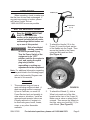
GASOLINE PRESSURE WASHER
13 HP - 4,000 PSI
Model 97005
Set up, Operating, and Servicing Instructions
Using an engine indoors CAN KILL YOU IN
MINUTES.
Engine exhaust contains carbon monoxide.
This is a poison you cannot see or smell.
NEVER use inside
a home or garage,
EVEN IF doors and
windows are open.
Only use OUTSIDE
and far away from
windows, doors, and
vents.
Visit our website at: http://www.harborfreight.com
Read this material before using this product.
Failure to do so can result in serious injury.
Save this manual.
Copyright© 2007 by Harbor Freight Tools®. All rights reserved. No portion of this manual or any artwork
contained herein may be reproduced in any shape or form without the express written consent of
Harbor Freight Tools. Diagrams within this manual may not be drawn proportionally. Due to continuing
improvements, actual product may differ slightly from the product described herein. Tools required for
assembly and service may not be included.
For technical questions or replacement parts, please call 1-800-444-3353.
Manual Revised 11h
table of contents
Important Safety Information.....................................................................3
Set-Up Precautions.....................................................................................4
Operating Precautions................................................................................4
Basic Specifications...................................................................................6
Unpacking....................................................................................................7
Set-Up Instructions.....................................................................................7
Operating Instructions................................................................................8
Starting The Engine....................................................................................9
Operating Tips...........................................................................................11
Technical Specifications...........................................................................14
Servicing....................................................................................................14
Troubleshooting...................................................................................17-18
Pump Parts List.........................................................................................19
Pump Assembly Diagram.........................................................................20
Engine Parts List.................................................................................21-22
Engine Assembly Diagram.......................................................................23
Frame, Lance, Hose, Wheel Parts List & Assembly Diagram...............24
Warranty Information..........................................................................25-26
SKU 97005
For technical questions, please call 1-800-444-3353.
Page 2
Save This Manual
Keep this manual for the safety
warnings and precautions, assembly,
operating, inspection, maintenance and
cleaning procedures. Write the product’s
serial number in the back of the manual
near the assembly diagram (or month
and year of purchase if product has no
number). Keep this manual and the
receipt in a safe and dry place for future
reference.
Important SAFETY
Information
In this manual, on the labeling,
and all other information
provided with this product:
This is the safety alert
symbol. It is used to alert
you to potential personal
injury hazards. Obey all
safety messages that
follow this symbol to avoid
possible injury or death.
DANGER indicates
a hazardous
situation which, if not
avoided, will result in death or
serious injury.
Danger
CAUTION, used
with the safety
alert symbol, indicates a
hazardous situation which, if
not avoided, could result in
minor or moderate injury.
Caution
Notice
NOTICE is used to
address practices
not related to personal injury.
Caution
CAUTION, without
the safety alert
symbol, is used to address
practices not related to
personal injury.
WARNING! Read all instructions.
Failure to follow all instructions
listed below may result in fire,
serious injury and/or DEATH.
The warnings and precautions
discussed in this manual cannot
cover all possible conditions and
situations that may occur. It must
be understood by the operator that
common sense and caution are
factors which cannot be built into
this product, but must be supplied
by the operator.
SAVE THESE INSTRUCTIONS
Safety warnings continue on next page.
WARNING
indicates a
hazardous situation which, if
not avoided, could result in
death or serious injury.
WARNING
SKU 97005
For technical questions, please call 1-800-444-3353.
Page 3
Set up precautions
1.
Gasoline fuel and fumes are
flammable, and potentially explosive.
Use proper fuel storage and handling
procedures. Do not store fuel or
other flammable materials nearby.
2.
Have multiple ABC class fire
extinguishers nearby.
3.
This equipment may not have a
spark arresting muffler included. A
spark arresting muffler is required
by law in California, on some US
Forest Service land, and possibly in
other areas or situations. Install an
approved spark arrestor before use
if legally required or if engine is to
be used near grass, brush, forests,
crops, or any other flammable
materials.
4.
Set up and use only on a flat, level,
well-ventilated surface.
5.
Wear ANSI-approved safety goggles,
heavy-duty work gloves, and dust
mask/respirator during set up.
6.
Use only oil and fuel recommended
in the “Specifications” section of this
manual.
SKU 97005
Operating precautions
1.
Carbon Monoxide
Hazard
Using an engine indoors
CAN KILL YOU IN
MINUTES.
Engine exhaust contains carbon
monoxide. This is a poison you
cannot see or smell.
NEVER use inside a home or garage,
EVEN IF doors and windows are
open.
Only use OUTSIDE and far away
from windows, doors, and vents.
2.
Keep children away from the
equipment, especially while it is
operating.
3.
Do not leave the equipment
unattended when it is running. Turn
off the equipment (and remove safety
keys, if available) before leaving the
work area.
4.
Wear ANSI-approved safety goggles
and hearing protection during use.
5.
People with pacemakers should
consult their physician(s) before
use. Electromagnetic fields in close
proximity to a heart pacemaker could
cause pacemaker interference
or pacemaker failure. Caution is
For technical questions, please call 1-800-444-3353.
Page 4
necessary when near the engine’s
magneto or recoil starter.
14. Keep the equipment, its engine, and
surrounding area clean at all times.
6.
Use only accessories that are
recommended by Harbor Freight
Tools for your model. Accessories
that may be suitable for one piece of
equipment may become hazardous
when used on another piece of
equipment.
7.
Do not operate in explosive
atmospheres, such as in the
presence of flammable liquids, gases,
or dust. Gasoline-powered engines
may ignite the dust or fumes.
15. Use the equipment, accessories, etc.,
in accordance with these instructions
and in the manner intended for the
particular type of equipment, taking
into account the working conditions
and the work to be performed. Use
of the equipment for operations
different from those intended could
result in a hazardous situation.
16. Do not operate the equipment with
known leaks in the engine’s fuel
system.
8.
Stay alert, watch what you are
doing and use common sense when
operating a piece of equipment. Do
not use a piece of equipment while
tired or under the influence of drugs,
alcohol or medication.
17. This product contains or, when
used, produces a chemical known
to the State of California to cause
cancer and birth defects or other
reproductive harm. (California Health
& Safety Code § 25249.5, et seq.)
9.
Do not overreach. Keep proper
footing and balance at all times.
This enables better control of the
equipment in unexpected situations.
18. When spills of fuel or oil occur, they
must be cleaned up immediately.
Dispose of fluids and cleaning
materials as per any local, state,
or federal codes and regulations.
Store oil rags in a bottom-ventilated,
covered, metal container.
10. Use this equipment with both hands
only. Using equipment with only
one hand can easily result in loss of
control.
11. Dress properly. Do not wear loose
clothing or jewelry. Keep hair,
clothing and gloves away from
moving parts. Loose clothes, jewelry
or long hair can be caught in moving
parts.
12. Parts, especially exhaust system
components, get very hot during use.
Stay clear of hot parts.
13. Do not cover the engine or equipment
during operation.
SKU 97005
19. Keep hands and feet away from
moving parts.
20. Before use, check for misalignment
or binding of moving parts, breakage
of parts, and any other condition
that may affect the equipment’s
operation. If damaged, have the
equipment serviced before using.
Many accidents are caused by poorly
maintained equipment.
21. Use the correct equipment for the
application. Do not modify the
equipment and do not use the
For technical questions, please call 1-800-444-3353.
Page 5
equipment for a purpose for which it
is not intended.
22. Never operate the Pressure Washer
using a pulsing action. Pulsing is
the repeated and rapid ON and
OFF operation of the Trigger. This
action could result in the failure of
components and connections that are
under pressure.
23. This is a clean, cold water Pressure
Washer. The working temperature
range must be between 41°
Fahrenheit and 104° Fahrenheit.
The water supply pressure must not
exceed 58 PSI and must be clean
and free of any abrasive particles or
corrosive contaminates.
24. Do not direct the water jet at live
electrical equipment or the Pressure
Washer itself.
Health & Safety Code 25249.5, et
seq.
31. Always ensure all water pressure is
released and the Pressure Washer
is turned off before attempting to
disconnect any Hoses or Connectors.
32. This Pressure Washer is rated for
domestic use only and should not be
used for professional or commercial
purposes.
33. Use caution when cleaning a vehicle
to prevent damaging the finish with a
high pressure water stream.
Service precautions
1.
a.Turn the engine switch to its
“OFF” position.
25. Do not direct the water jet at
yourself, others or pets.
26. Do not use the Pressure Washer to
pump gasoline, kerosene, or any
other flammable or corrosive liquids.
27. Do not leave the Pressure Washer
unattended while the machine is
running.
28. Never allow the Pressure Washer to
run for more than two minutes with
the Spray Gun in its closed position.
b.Allow the engine to completely
cool.
c. Then, remove the spark plug
wire(s) from the spark plug(s).
2.
Keep all safety guards in place and in
proper working order. Safety guards
include muffler, air cleaner, mechanical guards, and heat shields, among
other guards.
3.
Do not alter or adjust any part of
the equipment or its engine that is
sealed by the manufacturer or distributor. Only a qualified service
technician may adjust parts that
may increase or decrease governed engine speed.
4.
Wear ANSI-approved safety goggles,
heavy-duty work gloves, and dust
mask/respirator during service.
29. Do not allow the Pressure Washer
to run dry, as this will cause serious
damage to the Seals and Pump.
30. WARNING: The brass components
of this product contain lead, a
chemical know to the State of
California to cause birth defects (or
other reproductive harm). California
SKU 97005
Before service, maintenance, or
cleaning:
For technical questions, please call 1-800-444-3353.
Page 6
5.
6.
Maintain labels and nameplates on
the equipment. These carry important information. If unreadable or
missing, contact Harbor Freight Tools
for a replacement.
Have the equipment serviced by a
qualified repair person using only
identical replacement parts. This will
ensure that the safety of the equipment is maintained. Do not attempt
any service or maintenance procedures not explained in this manual
or any procedures that you are uncertain about your ability to perform
safely or correctly.
7.
Store equipment out of the reach of
children.
8.
Follow scheduled engine and equipment maintenance.
Refueling:
1.
Do not smoke, or allow sparks,
flames, or other sources of ignition
around the equipment, especially
when refuelling.
2.
Do not refill the fuel tank while the
engine is running or hot.
3.
Do not fill fuel tank to the top. Leave
a little room for the fuel to expand as
needed.
4.
Refuel in a well-ventilated area only.
Basic Specifications
Fuel
Engine
Oil
Pump Oil
Type
89+ octane unleaded gasoline
Capacity
1.7 Gallons
Type
SAE 25W (above 32° F)
SAE 15W-40 (at 32° F or below)
Capacity
37.2 Ounces (1.1L)
Type
SAE 25W (above 32° F)
SAE 15W-40 (at 32° F or below)
Capacity
15.2 Ounces (0.45L)
Note:Additional specifications found in the
Technical Engine Specifications
chart in this manual.
The emission control system for this
engine is warranted for standards set by
the U.S. Environmental Protection Agency
and by the California Air Resources Board
(also known as CARB-Phase II). For
warranty information, refer to the last
pages of this manual.
At high altitudes, the engine’s
carburetor, governor, and any other parts
that control the fuel-air ratio will need to be
adjusted by a qualified mechanic to allow
efficient high-altitude use and to prevent
damage to the engine and any other
devices used with this product.
Save these
instructions.
REV 09b
SKU 97005
For technical questions, please call 1-800-444-3353.
Page 7
Unpacking
HANDLE (10)
When unpacking, check to make sure
that the item is intact and undamaged. If
any parts are missing or broken, please
call Harbor Freight Tools at
1-800-444-3353 as soon as possible.
FIGURE A
BOLTS/NUTS
(11, 12)
Set Up Instructions
Read the entire Important
Safety Information
section at the beginning of this
manual including all text under
subheadings therein before set
up or use of this product.
FRAME (2)
2.
Risk of accidental
starting; resulting
in serious personal injury.
Turn the Power Switch of the
equipment to its “OFF”
position, wait for the engine to
cool, and unplug the spark
plug wire(s) before
assembling or making any
adjustments to the equipment.
WARNING
To attach the Handle (10) to the
Frame (2), insert the lower portion
of the Handle into the Frame. Then
secure the Handle to the Frame,
using two Bolts and two Nuts.
(See Figure A.)
Note: For additional information regarding
the parts listed in the following pages,
refer to the Assembly Diagram near
the end of this manual.
LOCK NUT (13)
Assembly
1.
This equipment may not have a
spark arresting muffler included. A
spark arresting muffler is required
by law in California, on some US
Forest Service land, and possibly in
other areas or situations. Install an
approved spark arrestor before use
if legally required or if engine is to
be used near grass, brush, forests,
crops, or any other flammable
materials.
SKU 97005
WHEEL (1)
3.
FIGURE B
To attach the Wheels (1), slide a
Wheel onto each end of the Axle
located at the front of the Frame (2).
Make sure air valve on wheel faces
outward. Then secure the Wheels to
the Axle, using one Lock Nut (13) for
each Wheel. (See Figure B.)
For technical questions, please call 1-800-444-3353.
Page 8
HOSE (8)
FIGURE E
INLET CONNECTOR
(59)
OUTLET CONNECTOR
(55)
CHOKE (41)
FUEL
VALVE
(104)
DETERGENT HOSE
SPRAY GUN (6)
FIGURE C
HOSE (8)
NOZZLE (9)
4.
FIGURE F
THROTTLE
(96)
Attach the Hose (8) to the Spray Gun
(6). Connect the other end of the
Hose to the Outlet Connector (55).
Connect a garden hose to the Inlet
Connector (59). Insert the Detergent
Hose into an approved container of
detergent. Then attach the desired
Nozzle (9) to the Spray Gun.
(See Figure C.)
Operating Instructions
Engine Controls
FIGURE G
ENGINE
SWITCH
(3)
STARTER HANDLE (1)
FIGURE D
SKU 97005
For technical questions, please call 1-800-444-3353.
Page 9
Starting the Engine
Inspect engine and equipment
looking for damaged, loose, and
missing parts before set up and
starting. If any problems are
found, do not use equipment until
fixed properly.
Checking Engine Oil Level
CAUTION! Your Warranty is VOID if the
engine’s Crankcase (13) is not properly
filled with oil before each use. Before
each use, check the oil level. Do not
run the engine with low or no engine
oil. Running the engine with no or low
engine oil WILL permanently damage the
engine.
32° F or above = SAE 25W
Below 32° F = SAE 15W-40
4.
Replace the Oil Dipstick.
(See Figure H.)
CAUTION! Do not run the engine with too
little or too much oil. The engine will be
permanently damaged.
Checking Fuel Level
Warning! To prevent fire,
shut the engine off and wait for
it to cool before adding fuel. Do
not smoke. Avoid refueling if
other equipment (which may
create sparks) is operating in the
immediate vicinity.
1.
To fill the Fuel Tank (101), unscrew and
remove the Fuel Tank Cap (109). (See
Figure I.)
FUEL TANK CAP (109)
FUEL TANK FILTER (108)
DIPSTICK (89)
FIGURE H
1.
Remove the dipstick and wipe it off with
a clean rag. (See Figure H.)
2.
Reinsert the dipstick completely and
remove it to check the oil level. The oil
level should be between the high and
low marks on the dipstick.
(See Figure H.)
3.
If the oil level is below the low mark add
the appropriate type of oil until the oil
level is between the high and the low
marks. (See Figure H.)
Oil type:
SKU 97005
FIGURE I
FUEL TANK (101)
2.
Check to make sure the Fuel Tank
Filter (108) is free of dirt and debris.
If necessary, remove and clean the
Filter. Then replace the Filter.
(See Figure I.)
For technical questions, please call 1-800-444-3353.
REV 09b, 09i
Page 10
3.
Mix fuel stabilizer (not included) with
89 octane (or better) unleaded gasoline according to fuel stabilizer directions.
4.
Fill the Fuel Tank (101) to about 1
inch under the lip of the gasoline tank
with the stabilized unleaded gasoline
mixture. (See Figure I.)
5.
Then replace the Fuel Tank Cap
(109). (See Figure I.)
Checking Pump Oil Level
CAUTION! Your Warranty is VOID if the
Pump’s Housing (13) is not properly
filled with oil before each use. Before
each use, check the oil level. Do not
run the Pump with low or no oil. Running the Pump with no or low oil WILL
permanently damage the Pump.
PUMP OIL GAUGE (26)
FIGURE J
OIL LEVEL WINDOW (28)
(PROPER OIL LEVEL)
1.
2.
OIL DRAIN PLUG (3)
Remove the Oil Gauge (26) and wipe
it off with a clean rag.
(See Figure J.)
Reinsert the Oil Gauge (26) completely and remove it to check the
oil level. The oil level should be
between the high and low marks on
the Gauge. Also, the proper oil level
can be visually observed through the
oil Level Window (28). The proper
oil level should appear midway in the
Window. (See Figure J.)
If the oil level is below the low mark
add the appropriate type of oil until
the oil level is between the high and
the low marks. Do not overfill.
(See Figure J.)
Oil type:
32° F or above = SAE 25W
Below 32° F = SAE 15W-40
3.
Replace the Oil Gauge.
(See Figure J.)
CAUTION! Do not run the Pump with too
little or too much oil. The Pump will
be permanently damaged.
Start Procedure
Before starting the engine:
a.Follow the Set Up
Instructions to prepare the
equipment.
b.Inspect the equipment and
engine.
c. Fill the engine with the
proper amount and type of
both fuel and oil.
Note: This engine includes an automatic
low oil shutdown sensor that disables
the engine if the oil level is too low.
d.Read the Equipment
Operation section that
follows.
1.
Turn the engine Fuel Valve (104) to
its “OPEN” position. (See Figure E.)
2.
Turn the Engine Switch (3) to its ON
or RUN position. (See Figure D.)
REV 09b; 09i
SKU 97005
For technical questions, please call 1-800-444-3353.
Page 11
3.
Then, turn the engine Choke (41) to
its “CHOKE” position. Set the Choke
in the “RUN” position when starting a
warm engine. (See Figure E.)
4.
Grasp the Starter Handle (1), and pull
slowly until resistance is felt. While
holding the Handle, allow the Starter
Rope to rewind slowly. Then, pull the
Starter Handle with a rapid, full arm
stroke. Once again, while holding
the Handle, allow the Rope to rewind
slowly. Repeat as necessary, until
the engine starts. (See Figure G.)
5.
4.
When finished spraying, press in to
fully engage the Safety on the Spray
Gun (6). Turn off the Engine, and
turn off the water supply. WARNING!
Do not disconnect the High Pressure Hose (8) or water inlet hose
until all pressure is discharged
safely.
5.
IMPORTANT! When turning off
the unit after use, high pressure
will remain inside the unit’s High
Pressure Hose (8), and the water
inlet hose. Point the Spray Gun (6) in
a safe direction and hold the Trigger
down for several seconds or until
water stops flowing from the Spray
Gun. The High Pressure Hose and
water inlet hose can be disconnected
after the pressure is released.
6.
Store the Pressure Washer and all
accessories in accordance with the
directions in the “Storage” section of
this manual.
After the engine starts, and once it
starts to warm up, slowly move the
Choke (41) to its “RUN” position.
(See Figure E.)
Pressure Washer Operation
1.
IMPORTANT! NEVER allow the
Pressure Washer to sit idle with
the Engine running for longer than
two minutes. The unit will build up
heat when it is on standby mode.
2.
Turn on the water supply, press in on
the Safety on the Spray Gun (6) and
squeeze its Trigger until water flows
out of the Gun without sputtering.
This removes air from the system and
allows the unit to properly perform.
Failure to follow this procedure
can damage the Pump.
3.
Hold the Spray Gun (6) firmly with
both hands. Point the Nozzle (9) in
a safe direction. Then, disengage
the Safety and squeeze the Trigger.
Make sure to turn off the Engine
whenever the Spray Gun is not in
use. Clean the area, following the
tips contained in the “Operating
Tips” section.
SKU 97005
IF ANY UNEXPECTED PROBLEMS
ARISE, PLEASE REFER TO THE “TROUBLESHOOTING” SECTION AT THE END
OF THIS MANUAL.
OPERATING TIPS
Adjusting The Spray Pattern
1.
You have a choice of four different
color-coded Nozzles (9) giving you
different spray patterns.
2.
0° Nozzle (colored red): This Nozzle delivers a pinpoint stream and is
extremely powerful. It covers a very
small area of cleaning. This Nozzle
should only be used on a surface that
can withstand this high pressure such
as metal or concrete. Do not use on
wood. Do not use to clean vehicles.
For technical questions, please call 1-800-444-3353.
Page 12
3.
4.
15° Nozzle (colored yellow): This
Nozzle delivers a powerful 15 degree
spray pattern for intense cleaning of
small areas. This Nozzle should only
be used on areas that can withstand
the high pressure from this Nozzle.
Do not use to clean vehicles.
40° Nozzle (colored white): This
Nozzle delivers a 40 degree spray
pattern and a less powerful stream
of water. It covers a wide area of
cleaning. This Nozzle should be
used for most general cleaning jobs
and for cleaning vehicles.
5.
Low Pressure Nozzle (colored
black): This Nozzle is used to apply
chemicals or cleaning solutions. It
has the least power stream. Do not
use to clean vehicles.
6.
NOTE: Before using the Pressure
Washer to clean patio paving slabs, it
is advisable to test a small area first.
Some paving slabs are manufactured
from inferior materials and the use of
a Pressure Washer could damage the
surface.
Using the Detergent Hose
1.
Fill a suitable container with pressure
washer detergent. Always follow
instructions as outlined in the
detergent manufacturer’s manual.
2.
Most automobile detergents are a
combination of a detergent and a
wax solution. These tend to be a
thick viscous liquid. The viscosity
(thickness) of the detergent will
increase in cold weather. It is
recommended that this type of
detergent is diluted with warm water
before filling the container. As a
general guide, a recommended
SKU 97005
dilution rate is 50/50. However, a trial
and error process would determine
the ideal dilution rate for a particular
detergent.
3.
A thick, viscous detergent will not flow
freely from the detergent container
and the residue will cause blockage
in the detergent flow system.
4.
After using a detergent the entire
Pressure Washer system should be
thoroughly flushed out with ample
amounts of water.
5.
If at any time the flow rate decreases,
sputters, or is inconsistent, release
the Trigger of the Spray Gun (6)
and turn off the Engine. Squeeze
the Trigger to release any pressure.
Then check the Nozzle (9) of the
Spray Gun for any blockage. If
blockage is suspected, clean the
Nozzle thoroughly. If the problem still
exists, check and clean the Filter on
the Detergent Hose.
Cleaning Recommendations
1.
Clean an inconspicuous test area
to help avoid damaging the surface.
Always begin with the fan spray at
a distance of about 3-5 feet from
the surface being cleaned to avoid
damaging the surface of the object.
Make sure the test area is clear of
people and water-prone delicate
objects. If a pressure washer
detergent is to be used, apply the
detergent to this area as well. After
cleaning this area, turn off the Engine
and inspect the area carefully for
any damage or discoloration. If any
damage is noted from the Nozzle
used, use a less powerful Nozzle
when cleaning the rest of the area.
For technical questions, please call 1-800-444-3353.
Page 13
If damage or discoloration is noted
from the detergent, do not use the
detergent when cleaning.
2.
First, pass over the area with a light
cleaning. Then clean the area more
thoroughly.
3.
For a vertical or sloped surface:
project, go over the edges of the
streaks with a wide fan pattern to
help blend these lighter areas in.
7.
If several different surfaces are to be
cleaned, make sure not to damage
any of the less solid surfaces while
attempting to clean the harder ones.
This is especially a concern when
cleaning tile and grout, bricks and
mortar, or stones and mortar.
8.
If wood is being cleaned, make
sure not to damage it. Pressure
washed wood will usually require
resurfacing (sanding) and re-coating
with a surface protectant (wood,
stain, varnish) after it has dried. Try
to avoid leaving water on a wooden
surface, as doing so can harm the
surface.
• Wash from the top down.
• If possible, direct the stream of
water in the same direction as the
slope towards a drainage area.
This will enable better drainage
and, therefore, better cleaning.
4.
For a flat surface:
• If a thin layer of water accumulates on the surface, periodically
use a stream of water to direct the
water toward the drainage.
• After the major cleaning is done,
sweep the surface with the stream
of water to help direct loose debris
toward the drainage.
5.
If detergent is to be applied, use only
pressure washing detergent. Other
detergents may clog or damage the
Pressure Washer. Apply the detergent at low pressure. Allow the detergent several minutes to sit and soak
into the work surface. This will improve cleaning efficiency. Make sure
to rinse off all detergent completely.
6.
Hold the Spray Gun (6) at about a
45° angle and steadily sweep the
water stream back and forth. If a
severe, head-on angle is used, dirt
may imbed in the surface being
cleaned. Follow a steady, consistent
pace during cleaning. This will help
prevent stripes or discoloration
afterwards. If streaking or uneven
cleaning is noted at the end of a
SKU 97005
For technical questions, please call 1-800-444-3353.
Page 14
Technical
Specifications
Engine Type
13 HP / OHV
Recoil Start
Air Cooled
3600 RPM
Displacement
390cc
Rotation viewed from PTO
Counterclockwise
(Facing the Shaft)
(power takeoff - the output
shaft)
Fuel
Engine
Oil
Spark Plug
Type
89+ octane unleaded gasoline
Capacity
1.7 Gallons
Type
SAE 25W (above 32° F)
SAE 15W-40 (at 32° F or below)
Capacity
37.2 Ounces (1.1L)
Types
LG F7RTC
Gap
0.027” to 0.031”
Engine
Approvals
California Emissions
U.S. EPA Phase II
Pump RPM
3400 RPM
Water Flow
4.0 Gal. Per Minute
Pressure
Rating
4,000 PSI
Pump Inlet
Pressure
30 PSI/4 Gal. Per Minute (Minimum)
80 PSI (Maximum)
Hose
Required
5/16” I.D.
Pump Oil
Type
SAE 25W (above 32° F)
SAE 15W-40 (at 32° F or below)
Capacity
15.2 Ounces (0.45L)
Water Temperature
Up to 104° F / 40°C
Nozzles Included
0° (Red)
15° (Yellow)
40° (white)
Chemical (Black)
Spray Gun Type
Safety Lock-Off Triggered
Handle
Hose Length
32 Ft.
Hose Fittings
Quick Connect
Hose Pressure
6000 PSI Maximum
Wheel Size & Inflation
4.10/3.50 Pneumatic
30 PSI (Cold)
Servicing
Risk of serious
personal injury
from accidental starting. Turn
the Power Switch of the
equipment to its “OFF”
position, wait for the engine to
cool, and unplug the spark
plug wire(s) before performing
any inspection, maintenance,
or cleaning procedures.
WARNING
Damaged equipment can fail,
causing serious personal
injury. Do not use damaged
equipment. If abnormal noise,
vibration, or excess smoking
occurs, have the problem
corrected before further use.
Maintenance Procedures
Many maintenance procedures,
including any not detailed
in this manual, will need to
be performed by a qualified
technician for safety. If you
have any doubts about your
ability to safely service the
equipment or engine, have a
qualified technician service the
equipment instead.
Engine Oil Change
CAUTION! Oil is very hot during
operation and can cause burns. Wait
for engine to cool before changing oil.
1.
Place a drain pan (not included)
underneath the Crankcase’s Drain
Plug (14). (See Figure K, next
page.)
REV 09b
SKU 97005
For technical questions, please call 1-800-444-3353.
Page 15
2.
Remove a second Wing Nut (47) and
its Washer (48). Then remove the Air
Filter Element (49).
3.
For filter elements:
To prevent injury from dust and
debris, wear ANSI-approved safety
goggles, NIOSH-approved dust
mask/respirator, and heavy-duty work
gloves. In a well-ventilated area
away from bystanders, stand down
wind, and use pressurized air to blow
dust out of the Air Filter Element
(49). If this does not get the Filter
reasonably clean, replace it.
4.
Install the new filter or the cleaned
filter. Secure the Air Cleaner Cover
before use.
DRAIN PLUG (14)
FIGURE K
2.
Remove the Drain Plug (14) and, if
possible, tilt the Crankcase slightly to
help drain the oil out. Recycle used
oil.
3.
Replace the Drain Plug (14) and
tighten it.
4.
Refill the oil to the proper level following the instructions under the “Starting the Engine” section.
Spark Plug Maintenance
1.
Disconnect spark plug wire from
end of plug. Clean out debris from
around spark plug.
SPARK PLUG (60)
SPARK PLUG WIRE
Air Filter Element Maintenance
FIGURE L
FIGURE N
AIR CLEANER COVER (51)
WING NUT (47)
1.
The Air Cleaner Cover (51) is held in
place by a Wing Nut (47). Remove it.
(See Figure L.)
SKU 97005
2.
Using a spark plug wrench, remove
the spark plug. (See Figure N.)
3.
Inspect the spark plug:
If the electrode is oily, clean it using a clean, dry rag. If the electrode
has deposits on it, polish it using
For technical questions, please call 1-800-444-3353.
Page 16
emery paper. If the white insulator is
cracked or chipped, the spark plug
needs to be replaced.
4.
When installing a new spark plug, adjust the plug’s gap to the specification
on the Technical specification chart.
Do not pry against the electrode, the
spark plug can be damaged.
5.
Install the new spark plug or the
cleaned spark plug into the engine.
Then re-attach the Spark Plug Wire.
SKU 97005
For technical questions, please call 1-800-444-3353.
Page 17
Troubleshooting
Problem
Engine will not start
Possible Causes
Probable Solutions
Fuel Related:
1. No fuel in tank or fuel valve closed.
2. Choke not in start position,
especially with cold engine.
3. Low quality or deteriorated, old
gasoline.
4. Carburetor not primed.
Fuel Related:
1. Fill fuel tank and open fuel valve.
2. Move choke to start position if
engine is cold.
3. Use only fresh 89+ octane
unleaded gasoline.
4. Prime carburetor by pressing
priming bulb approximately three
times.
5. Dirty fuel passageways blocking
5. Clean out passageways using
fuel flow.
fuel additive. Heavy deposits may
require further cleaning.
6. Carburetor needle stuck. Fuel can
6. Gently tap side of carburetor float
be smelled in the air.
chamber with screwdriver handle.
7. Too much fuel in chamber. This can 7. Turn choke to run position.
be caused by the carburetor needle
Remove spark plug and pull the
sticking.
start handle several times to air out
the chamber. Reinstall spark plug
and set choke to start position.
Ignition (spark) Related:
1. Spark plug wire not connected
securely.
2. Spark plug electrode wet or dirty.
3. Incorrect spark plug gap.
4. Spark plug wire broken.
5. Incorrect spark timing or faulty
ignition system.
Ignition (spark) Related:
1. Connect spark plug wire properly.
Compression Related:
1. Cylinder not lubricated. Problem
after long storage periods.
Compression Related:
1. Pour tablespoon of oil into spark
plug hole. Crank engine a few
times and try to start again.
2. Tighten spark plug. If that does
not work, replace spark plug. If
problem persists, may have head
gasket problem, see #3.
3. Tighten head. If that does not
remedy problem, replace head
gasket.
4. Adjust valve clearance. If that does
not work, clean or replace valves/
tappets.
2. Loose or broken spark plug.
(Hissing noise will occur when
trying to start.)
3. Loose cylinder head or damaged
head gasket. (Hissing noise will
occur when trying to start.)
4. Engine valves or tappets
misadjusted or stuck.
2. Clean spark plug.
3. Correct spark plug gap.
4. Replace spark plug wire.
5. Have qualified technician diagnose/
repair ignition system.
Follow all safety precautions whenever diagnosing or servicing the
equipment or engine.
SKU 97005
For technical questions, please call 1-800-444-3353.
Page 18
Troubleshooting
Problem
Engine misfires
Possible Causes
1. Spark plug wire loose.
2. Incorrect spark plug gap or
damaged spark plug.
3. Defective spark plug wire.
4. Old or low quality gasoline.
5. Incorrect compression.
Engine stops
suddenly
1. Low oil shutdown.
2. Fuel tank empty or full of impure or
low quality gasoline.
3. Defective fuel tank cap creating
vacuum, preventing proper fuel
flow.
4. Faulty magneto.
Engine knocks
1. Old or low quality gasoline.
2. Engine overloaded.
3. Incorrect spark timing, deposit
buildup, worn engine, or other
mechanical problems.
Engine backfires
1. Impure or low quality gasoline.
2. Engine too cold.
3. Intake valve stuck or overheated
engine.
Probable Solutions
1. Check wire connections.
2. Re-gap or replace spark plug.
3. Replace spark plug wire.
4. Use only fresh 89+ octane
unleaded gasoline.
5. Diagnose and repair compression.
(Use Engine will not start:
Compression Related
section.)
1. Fill engine oil to proper level.
Check engine oil before EVERY
use.
2. Fill fuel tank with fresh 89+ octane
unleaded gasoline.
3. Test/replace fuel tank cap.
4. Have qualified technician service
magneto.
1. Fill fuel tank with fresh 89+ octane
unleaded gasoline.
2. Do not exceed equipment’s load
rating.
3. Have qualified technician diagnose
and service engine.
1. Fill fuel tank with fresh 89+ octane
unleaded gasoline.
2. Use cold weather fuel and oil
additives to prevent backfiring.
3. Have qualified technician diagnose
and service engine.
Follow all safety precautions whenever diagnosing or servicing the
equipment or engine.
SKU 97005
For technical questions, please call 1-800-444-3353.
Page 19
PLEASE READ THE FOLLOWING
CAREFULLY
Q’ty
O-Ring (50 x 2.65)
1
24
Connecting Flange
1
25
Screw (M8 x 25)
4
26
Oil Gauge
1
27
Plastic Washer (20 x 15.8 x 1)
1
28
Oil Level Window
1
29
Screw (M6 x 55)
8
30
O-Ring (11.8 x 1.8)
6
31
Valve Seat
6
32
Valve Plate
6
33
Valve Spring
6
34
Valve Jacket
6
35
Bulkhead
4
36
O-Ring (15 x 1.8)
3
37
Valve Seat
1
38
O-Ring (11.2 x 1.8)
1
39
Unload Valve
1
40
Detergent Injection Connector
1
41
O-Ring (4.5 x 1.8)
1
42
Steel Ball (5.5)
1
43
Spring
1
44
O-Ring (24 x 1.8)
3
Q’ty
PUMP PARTS LIST
Description
Description
23
The manufacturer and/or distributor
has provided the parts list and assembly
diagram in this manual as a reference
tool only. Neither the manufacturer or
distributor makes any representation
or warranty of any kind to the buyer
that he or she is qualified to make any
repairs to the product, or that he or
she is qualified to replace any parts of
the product. In fact, the manufacturer
and/or distributor expressly states
that all repairs and parts replacements
should be undertaken by certified and
licensed technicians, and not by the
buyer. The buyer assumes all risk and
liability arising out of his or her repairs
to the original product or replacement
parts thereto, or arising out of his or
her installation of replacement parts
thereto.
Part
Part
45
Subsidiary Seal Ring Seat
3
1
Screw (M6 x 16)
10
46
Subsidiary Seal Ring
3
2
Spring Washer (#6)
24
47
Main Seal Ring Seat
3
3
Oil Drain Plug
2
48
V-Seal Ring
3
4
O-Ring (13.2 x 2.65)
3
49
V-Compaction Ring
3
5
Back Cover
1
50
Pump Body
1
6
Seal
1
51
O-Ring (4 x 2.65)
1
7
Cover
1
52
Check Valve Core
1
8
O-Ring (47.5 x 1.8)
1
53
Check Valve Spring
1
9
Bolt (M8 x 16)
1
54
O-Ring (12.5 x 1.8)
1
10
Spring Washer (#8)
5
55
Outlet Connector
1
11
Gasket (#8)
1
56
Screw Jacket
1
12
Bearing (304)
1
57
Nut
1
13
Housing
1
58
Filter
1
14
Pin
3
59
Inlet Connector
1
15
Plunger
3
60
Plastic Gasket
1
16
Oil Seal
3
61
Thermal Protection
1
17
Water Block Ring
3
62
Plunger
2
18
Connecting Rod
3
19
Crank Shaft
1
20
Bearing (NK140/20)
1
21
Retaining Ring (#40)
1
22
Seal Ring (38 x 58 x 8)
1
SKU 97005
IMPORTANT:
When ordering Pump parts,
make sure to specify
“PUMP”
and the part number.
(i.e., “PUMP” Part #1, Screw)
For technical questions, please call 1-800-444-3353.
Page 20
SKU 97005
56
55
37
54
53
52
51
57
61
58
59
60
34
62
33
43
42
41
40
32
31
30
For technical questions, please call 1-800-444-3353.
34
29
33
2
37
38
39
19
32
31
36
35
30
50
49
48
18
20
47
21
46
23
45
22
44
24
17
16
15
10
25
4
3
14
4
26
12
13
11
10
2
9
1
8
6
27
7
28
5
2
4
1
3
PUMP ASSEMBLY DIAGRAM
Page 21
ENGINE PARTS LIST
Part
Description
Qty.
Part
Description
Qty.
1
Starter Handle
1
39
Carburetor Packing
1
2
Flange Bolt (M6 x 8)
3
40
Carburetor Assy.
1
3
Engine Switch
1
41
Choke
1
4
Fan Cover
1
42
Air Cleaner Packing
2
5
Flange Bolt (M6 x 12)
12
43
Flange Nut (M6)
5
6
Shroud
1
44
Air Cleaner Case
1
7
Starter Pulley
1
45
Flange Bolt (M6 x 20)
1
8
Cooling Fan
1
46
Air Cleaner Seal
1
9
Flange Nut (M16)
1
47
Wing Nut (M6)
2
10
Wire Harness Clip
1
48
Drain Lug Washer
2
11
Flywheel
1
49
Air Cleaner Element
1
12
Oil Seal (35 x 52 x 8)
2
50
Air Cleaner Separator
1
13
Crank Case Assy.
1
51
Air Cleaner Cover
1
14
Drain Plug
2
52
Head Cover Bolt
1
15
Amplifier
1
53
Head Cover Washer
1
16
Drain Lug Washer
2
54
Head Cover
1
17
Wire Clip
1
55
Exhaust Pipe
1
18
Flange Bolt (M6 x 25)
2
56
Flange Bolt (M10 x 80)
4
19
Ignition Coil Assy.
1
57
Breather Tube
1
20
Grommet Cord
1
58
Cylinder Head
1
21
Cord Stop Switch
1
59
Head Bolt (M8 x 34)
2
22
Oil Seal (8 x 14 x 5)
1
60
Spark Plug
1
23
Radial Ball Bearing (6202)
2
61
Cam Shaft Assy.
1
24
Governor Arm Shaft
1
62
Valve Lifter
2
25
Lock Pin (10mm)
1
63
Intake Valve
1
26
Washer (8.2 x 17 x 0.8)
1
64
Exhaust Valve
1
27
Flange Nut (M10)
1
65
Push Rod
2
28
O-Ring (14mm)
1
66
Valve Spring Seat
1
29
Oil Level Switch Assy.
1
67
Valve Spring
2
30
Balancer Weight
1
68
Intake Valve Spring Retainer
1
31
Crank Shaft
1
69
Push Rod Guide Plate
1
32
Key
1
70
Pivot Bolt
2
33
Radial Ball Bearing (6207)
2
71
Valve Rotator
1
34
Cylinder Head Gasket
1
72
Exhaust Valve Spring Retainer
1
35
Dowel Pin (12 x 20)
2
73
Valve Rocker Arm
2
36
Head Bolt (8 x 111)
2
74
Valve Rocker Arm Nut
2
37
Insulator Packing
1
75
Pivot Adjusting Nut
2
38
Carburetor Insulator
1
76
Flange Nut (M8)
6
IMPORTANT:
When ordering Engine parts,
make sure to specify
“ENGINE”
and the part number.
(i.e., “ENGINE” Part #1, Starter Recoil)
SKU 97005
IMPORTANT:
When ordering Engine parts,
make sure to specify
“ENGINE”
and the part number.
(i.e., “ENGINE” Part #1, Starter Recoil)
For technical questions, please call 1-800-444-3353.
Page 22
Part
Qty.
Part
77
Exhaust Pipe Gasket
Description
1
94
Piston
1
78
Exhaust Pipe
1
95
Connecting Rod Assy.
1
79
Muffler Stay
1
96
Throttle Assy.
1
80
Spark Arrester
1
97
Governor Spring
1
81
Muffler
1
98
Throttle Return Spring
1
82
Muffler Guard
1
99
Governor Arm Bolt
1
83
Tapping Screw (M5 x 8)
5
100
Governor Arm
1
84
Flange Bolt (M8 x 40)
7
101
Fuel Tank
1
85
Oil Cap
1
102
Flange Bolt (M8 x 25)
2
86
Crank Case Cover
1
103
Rubber Supporter
1
87
Case Cover Packing
1
104
Fuel Valve
1
88
Dowel Pin (8 x 12)
2
105
Outlet Pipe (4.5 x 235)
1
89
Dipstick
1
106
Fuel Tank Joint
1
90
Governor Kit
1
107
Fuel Tank Rubber Joint
1
91
Piston Pin Clip
2
108
Fuel Tank Filter
1
92
Piston Pin
1
109
Fuel Tank Cap
1
93
Pistion Ring Set Assy.
1
IMPORTANT:
When ordering Engine parts,
make sure to specify
“ENGINE”
and the part number.
(i.e., “ENGINE” Part #1, Starter Recoil)
SKU 97005
Description
Qty.
IMPORTANT:
When ordering Engine parts,
make sure to specify
“ENGINE”
and the part number.
(i.e., “ENGINE” Part #1, Starter Recoil)
For technical questions, please call 1-800-444-3353.
Page 23
ENGINE ASSEMBLY DIAGRAM
SKU 97005
For technical questions, please call 1-800-444-3353.
Page 24
13
SKU 97005
For technical questions, please call 1-800-444-3353.
11, 12
Wheel
Frame
Hose Shelf
Gun Shelf
Screw
Spray Gun
Lance
High Pressure Hose
Nozzle
Handle
Bolt
Self Locking Nut
Lock Nut
1
2
3
4
5
6
7
8
9
10
11
12
13
Description
LANCE, HOSE, WHEEL PARTS LIST
Part
IMPORTANT:
When ordering parts, make sure to specify
“FRAME”, “GUN”, “LANCE”, “WHEEL”, “GUN SHELF”, or “HOSE SHELF”
and the part number.
(i.e., “WHEEL” Part #1, Wheel)
10
2
2
2
1
4
1
1
1
3
1
3
1
2
Qty.
FRAME, LANCE, HOSE, WHEEL PARTS LIST & ASSEMBLY DIAGRAM
Page 25
90 Day warranty
Harbor Freight Tools Co. makes every effort to assure
that its products meet high quality and durability standards,
and warrants to the original purchaser that this product is free
from defects in materials and workmanship for the period of 90
days from the date of purchase. This warranty does not apply to
damage due directly or indirectly, to misuse, abuse, negligence
or accidents, repairs or alterations outside our facilities, criminal
activity, improper installation, normal wear and tear, or to lack of
maintenance. We shall in no event be liable for death, injuries
to persons or property, or for incidental, contingent, special or
consequential damages arising from the use of our product.
Some states do not allow the exclusion or limitation of incidental
or consequential damages, so the above limitation of exclusion
may not apply to you. This warranty is expressly in lieu of all
other warranties, express or implied, including the warranties of
merchantability and fitness.
To take advantage of this warranty, the product or
part must be returned to us with transportation charges prepaid.
Proof of purchase date and an explanation of the complaint must
accompany the merchandise. If our inspection verifies the defect,
we will either repair or replace the product at our election or we
may elect to refund the purchase price if we cannot readily and
quickly provide you with a replacement. We will return repaired
products at our expense, but if we determine there is no defect,
or that the defect resulted from causes not within the scope of our
warranty, then you must bear the cost of returning the product.
Manufacturer’s Warranty Coverage
The 1995 and later engines are warranted for two (2) years.
If any emission-related part on your engine is defective, the part
will be repaired or replaced by HFT.
Harbor Freight Tools Emission Control Defects
Warranty Coverage
Engines are warranted for a period of two (2) years relative to
emission control parts defects, subject to the provisions set forth
below. If any emission related part on your engine is defective, the
part will be repaired or replaced by HFT.
Owner’s Warranty Responsibilities
• As the engine owner, you are responsible for the performance
of the required maintenance listed in your Owner’s Manual.
HFT recommends that you retain all receipts covering
maintenance on your engine, but HFT cannot deny warranty
solely for the lack of receipts or for your failure to ensure the
performance of all scheduled maintenance.
• As the engine owner, you should, however, be aware that
HFT may deny you warranty coverage if your engine or a part
has failed due to abuse, neglect, improper maintenance, or
unapproved modifications.
• You are responsible for shipping your engine to a HFT
warranty station as soon as a problem exists. Contact the
HFT Customer Service department at the number below to
make shipping arrangements. The warranty repairs should
be completed in a reasonable amount of time, not to exceed
30 days.
This warranty gives you specific legal rights and you may
also have other rights which vary from state to state.
If you have any questions regarding your warranty rights
and responsibilities, you should contact the Harbor Freight Tools
Customer Service Department at 1-800-444-3353.
3491 Mission Oaks Blvd. • PO Box 6009 • Camarillo, CA
93011 • (800) 444-3353
Harbor Freight Tools Emission Control Defects
Warranty Provisions
Emission Control
System Warranty
California and United States Emission Control
Defects Warranty Statement
The California Air Resources Board (herein CARB), the
United States Environmental Protection Agency (herein EPA),
and Harbor Freight Tools (herein HFT) are pleased to explain the
emission control system warranty on your 1995 and later Small
Off-Road Engine (herein engine). In California, the engine must
be designed, built and equipped to meet the State’s stringent antismog standards. Elsewhere within the United States, new off-road,
spark-ignition engines certified for model year 1997 and later, must
meet similar standards set forth by the EPA. HFT must warrant
the emission control system on your engine for the periods of time
described below, provided there has been no abuse, neglect or
improper maintenance of your engine.
1. Length of Coverage
HFT warrants to a first retail purchaser and each subsequent
purchaser that the engine is free from defects in materials
and workmanship that cause the failure of warranted parts
for a period of two (2) years after the date of delivery to the
first retail purchaser.
2. No Charge Repair or Replacement
Repair or replacement of any warranted part will be performed
at no charge to the owner if the work is performed through a
warranty station authorized by HFT. For emissions warranty
service, contact the HFT Customer Service Department at
1-800-444-3353.
3.Consequential Damages Coverage
Coverage under this warranty shall also extend to the failure
of any engine components caused by the failure of any
warranted part while it is still covered under this warranty.
Your emission control system may include parts such as the
carburetor or fuel-injection system, and the ignition system. Also
included may be hoses, belts, connectors and other emissionrelated assemblies.
Where a warrantable condition exists, HFT will repair your
engine at no cost to you including diagnosis, parts and labor.
REV 11h
SKU 97005
For technical questions, please call 1-800-444-3353.
Page 26
4.Coverage Exclusions
Warranty claims shall be filed in accordance with the
provisions of the HFT warranty policy explained in the box
at the top of the previous page. HFT shall not be liable for
any loss of use of the engine, for any alternative usage,
for any damage to goods, loss of time, or inconvenience.
Warranty coverage shall also be excluded for any part which
fails, malfunctions, or is damaged due to failure to follow
the maintenance and operating instructions set forth in the
Owner’s Manual including, but not limited to:
a) Use of parts which are not authorized by HFT
b) Improper installation, adjustment or repair of the engine
or of any warranted part unless performed by an
authorized warranty center
c) Failure to follow recommendations on fuel use contained
in the Owner’s Manual
d) Improper or inadequate maintenance of any warranted
parts
e) Repairs performed outside of the authorized warranty
service dealers
f) Alterations by changing, adding to or removing parts
from the engine.
Record Product’s Serial Number Here:
_______________________________
Note:If product has no serial number, record
month and year of purchase instead.
Note:Some parts are listed and shown for
illustration purposes only, and are not
available individually as replacement parts.
5. Service and Maintenance
Component parts which are not scheduled for replacement
as required maintenance or are scheduled only for regular
inspection to the effect of “repair or replace as necessary”
are warranted for the warranty period. Any warranted part
which is scheduled for replacement as required maintenance
is warranted for the period of time up to the first scheduled
replacement point for that part. Any replacement part,
provided it is equivalent in durability and performance,
may be used in performance of maintenance or repairs.
The owner is responsible for commissioning a qualified
technician/mechanic to perform all required maintenance,
as outlined in the Inspection, Cleaning, and Maintenance
section in this manual.
6. Warranted Parts
1)
Fuel Metering System
i) Carburetor and its internal parts.
ii) Fuel pump (if so equipped).
iii) Cold start enrichment system.
2) Air Induction System
i) Intake pipe/manifold.
ii) Air cleaner.
3) Ignition System
i) Spark plug.
ii) Magneto ignition system.
4)Catalyst System (if so equipped)
i) Exhaust pipe stud.
ii) Muffler.
iii) Catalytic converter (if so equipped).
5) Miscellaneous Items Used in Above Systems
i) Vacuum, temperature and time sensitive valves
and switches.
ii) Hoses, belts, connectors, and assemblies.
SKU 97005
For technical questions, please call 1-800-444-3353.
Page 27