1
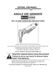
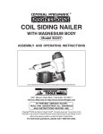
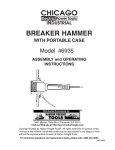
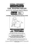
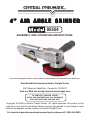
4” AIR ANGLE GRINDER
95504
ASSEMBLY AND OPERATING INSTRUCTIONS
Due to continuing improvements, actual product may differ slightly from the product described herein.
Distributed Exclusively by Harbor Freight Tools®
3491 Mission Oaks Blvd., Camarillo, CA 93011
Visit our Web site at http://www.harborfreight.com
TO PREVENT SERIOUS INJURY,
READ AND UNDERSTAND ALL WARNINGS
AND INSTRUCTIONS BEFORE USE.
Copyright © 2006 by Harbor Freight Tools®. All rights reserved. No portion of this
manual or any artwork contained herein may be reproduced in any shape or form
without the express written consent of Harbor Freight Tools.
For technical questions and replacement parts, please call 1-800-444-3353.
Specifications
ITEM
Overall Dimensions
Handle Dimensions
Inlet Size
Max. Rated Air Pressure
Air Consumption
Maximum Speed
Wheel Material
Wheel Dimensions
Arbor Diameter
Spindle Thread
Net Weight
DESCRIPTION
7-1/2” L x 5” W x 3-3/4” H
1”Dia. x 3-1/8”L (left side only)
1/4” - 18 NPT Female thread
90 PSI
6 CFM @90 PSI
10,000 RPM
Resin bonded aluminum oxide grit
4” Diameter x 1/4”Thickness
5/8”
3/8”
2.65 Lbs.
Save This Manual
You will need the manual for the safety warnings and precautions, assembly
instructions, operating and maintenance procedures, parts list and diagram. Keep
your invoice with this manual. Write the invoice number on the inside of the front
cover. Keep the manual and invoice in a safe and dry place for future reference.
Safety Warnings and Precautions
WARNING: When using tool, basic safety precautions should always be
followed to reduce the risk of personal injury and damage to equipment.
Read all instructions before using this tool!
1.
Keep work area clean. Cluttered areas invite injuries.
2.
Observe work area conditions. Do not use machines or power tools in
damp or wet locations. Don’t expose to rain. Keep work area well lighted. Do
not use electrically powered tools in the presence of flammable gases or
liquids.
3.
Keep children away. Children must never be allowed in the work area. Do
not let them handle machines, tools, or extension cords.
4.
Store idle equipment. When not in use, tools must be stored in a dry
location to inhibit rust. Always lock up tools and keep out of reach of
children.
5.
Do not force tool. It will do the job better and more safely at the rate for
which it was intended. Do not use inappropriate attachments in an attempt
to exceed the tool capacity.
SKU 95504
Page 2
07i
6.
Use the right tool for the job. Do not attempt to force a small tool or
attachment to do the work of a larger industrial tool. There are certain
applications for which this tool was designed. Do not modify this tool and do
not use this tool for a purpose for which it was not intended.
7.
Dress properly. Do not wear loose clothing or jewelry as they can be caught
in moving parts. Protective, electrically non-conductive clothes and non-skid
footwear are recommended when working. Wear restrictive hair covering to
contain long hair.
8.
Use eye and ear protection. Always wear ANSI approved impact safety
goggles. Wear a full face shield if you are producing metal filings or wood
chips. Wear an ANSI approved dust mask or respirator when working around
metal, wood, and chemical dusts and mists.
9.
Do not overreach. Keep proper footing and balance at all times. Do not
reach over or across running machines.
10. Maintain tools with care. Keep tools sharp and clean for better and safer
performance. Follow instructions for changing accessories. Inspect tool
cords periodically and, if damaged, have them repaired by an authorized
technician. The handles must be kept clean, dry, and free from oil and
grease at all times.
11. Disconnect when not in use. Disconnect tool from air compressor hose
when not in use.
12. Remove adjusting keys and wrenches. Check that keys and adjusting
wrenches are removed from the tool or machine work surface before plugging
it in.
13. Avoid unintentional starting. Be sure the switch is in the Off position when
not in use and before plugging in.
14. Stay alert. Watch what you are doing, use common sense. Do not operate
any tool when you are tired.
15. Take caution as some woods contain preservatives such as copper
chromium arsenate (CCA) which can be toxic. When working with these
materials extra care should be taken to avoid inhalation and minimize skin
contact.
16. Check for damaged parts. Before using any tool, any part that appears
damaged should be carefully checked to determine that it will operate
properly and perform its intended function. Check for alignment and binding of
moving parts, and any other condition that may affect proper operation. Any
part that is damaged should be properly repaired or replaced by a qualified
technician. Do not use the tool if any switch does not turn On and Off
properly.
SKU 95504
Page 3
17. Guard against electric shock. Prevent body contact with grounded surfaces
such as pipes, radiators, ranges, and refrigerator enclosures.
18. Replacement parts and accessories. When servicing, use only identical
replacement parts. Use of any other parts will void the warranty. Only use
accessories intended for use with this tool. Approved accessories are
available from Harbor Freight Tools.
19. Do not operate tool if under the influence of alcohol or drugs. Read
warning labels on prescriptions to determine if your judgment or reflexes are
impaired while taking drugs. If there is any doubt, do not operate the tool.
20. Use proper size and type extension cord. If an extension cord is required
for an air compressor, it must be of the proper size and type to supply the
correct current to the tool without heating up. Otherwise, the extension cord
could melt and catch fire, or cause electrical damage to the tool. This tool
requires use of an extension cord of 0 to 10 amps capability (up to 50 feet),
with wire size rated at 18 AWG. Longer extension cords require larger size
wire. If you are using the air compressor outdoors, use an extension cord
rated for outdoor use. (signified by “WA” on the jacket).
21. Maintenance. For your safety, service and maintenance should be performed
regularly by a qualified technician.
22. Use clean, dry, regulated, compressed air at 90 PSI. Do not exceed the
recommended 90 PSI. Never use oxygen, carbon dioxide, combustible gases
or any other bottled gas as a power source for these tools.
Note: Performance of this tool (if powered by line voltage) may vary depending on
variations in local line voltage. Extension cord usage may also affect tool performance.
Warning: This product contains or produces a chemical known to the State of
California to cause cancer and birth defects (or other reproductive harm). (California Health & Safety Code § 25249.5 et seq.).
Warning: The warnings, cautions, and instructions discussed in this instruction manual cannot cover all possible conditions and situations that may occur. It must be understood by the operator that common sense and caution are
factors which cannot be built into this product, but must be supplied by the
operator.
Special Warnings for This Tool
1.
There are certain applications for which this tool was designed. Harbor Freight
Tools strongly recommends that this tool not be modified and/or used for any
application other than which it was designed.
SKU 95504
Page 4
2.
All accessories must be rated for at least the RPM speed recommended on
the tool's warning label. Wheels and other accessories running over rated
speed can fly apart and cause injury.
3.
For safest operation, it is recommended that only these accessories be used
with this product: Abrasive Cut-Off Discs and Wheels, Flap Wheels, Wire
Brushes, Wire Wheel Brushes.
4.
Always use an approved and proper guard when using the above mentioned
accessories. Each accessory must have the correct arbor size and must fit
properly on the Gear Shaft. Make sure accessories are tightened down
securely.
5.
Always disconnect from power source before adding or removing
accessories. Use a cloth or glove to protect hands from abrasion.
6.
The Handle must be used at all times to maintain complete control of the tool.
Two-handed operation is required at all times.
WARNING: Never install a carbide tipped or steel circular saw blade for use
with this Angle Grinder! Never install a wood carving blade, carving disc with
saw chain cutters, or a cutting carving disc on this Angle Grinder!
Unpacking
When unpacking, check to make all parts listed on Page 8 are included. If any
parts are missing or broken, please call Harbor Freight Tools at the number on
the cover of this manual.
Angle
Grinder
Air Connection
Note: Air Compressor is not supplied. You will need an Air Compressor with a
minimum rating of One Horsepower, 6 CFM delivery at 90 PSI, and a 12 Gallon Air
Tank.
You may use Couplings (not supplied) as shown in the Diagram above. Do not
connect Couplers directly to the Air Inlet. Doing so will increase the overall bulk of
the tool and strain the Inlet Threads.
SKU 95504
Page 5
1.
Be sure to follow all safety precautions as listed on Pages 2-5 of this manual.
2.
Acquire a 1/4” NPT air fitting (not supplied) and screw into the Air Inlet fitting.
Tighten with a wrench.
3.
Attach a quick-coupler (not supplied) to the air fitting if desired. This allows
quick exchange of the Air Hose to other air tools.
4.
Once the air compressor is off, connect the Air Hose to the Air Inlet Coupling.
This air tool requires lubrication during operation. For best results, it is recommended to have an oiler and water filter in line with the air supply as shown. This
will extend the life of the tool.
Attaching/Changing the
Wheel Accessory
1.
Fit the U-shaped end of the
Stop Spanner [33] around
the Gear Shaft [6] and hold
in place to prevent the
Shaft from spinning. Insert
the two prongs on the end
of the Disc Spanner [34]
into the corresponding
holes in the Disc Nut [1]
and turn your wrist to unscrew the Disc Nut. See Fig. A, right.
Fig. A
2.
Slide the Disc Wheel [2] onto the Shaft.
3.
Replace the Disc Nut and tighten using the Stop Spanner and Disc Spanner.
DANGER Grinding wheel used must be rated at 11,000 RPM or
higher.
Operation
1.
Always wear ANSI approved impact safety goggles when setting up and using
this tool.
2.
Tighten all work pieces to your work surface with a clamp or vise so that both
of your hands are free to operate the Grinder.
3.
Screw the Handle [35] into the threaded inlet on the side of the Angle
Housing [13] as shown in the Assembly Diagram on Page 8.
4.
Set the Air Compressor’s pressure regulator to 90 PSI. Connect the Grinder
to the Air Compressor’s hose.
SKU 95504
Page 6
5.
Check to be sure all attachments are secure before turning on the tool. Adjust
the Wheel Guard so that it provides a shield between you (the user) and the
material you are working on. The Wheel Guard must be in place at all
times when using the Angle Grinder.
6.
Grip the Handle [35] with your left hand and the Housing [25] with your right
hand. Depress the Lever [31] with your right hand to turn the tool on. Allow
the motor to reach its full speed before grinding. Make sure the Wheel is
rotating evenly and all parts appear to be working properly. Always maintain a
firm grip with both hands when operating this tool.
7.
To begin cutting or grinding, approach the material at an angle between 15
and 30 degrees to the Wheel. Maintain that angle until you are finished
cutting/grinding. Do not force the Wheel or apply too much pressure. If the
Wheel slows down as you work with your material, you are applying too
much pressure.
8.
Once you have turned the Grinder off, continue to hold onto the tool with
both hands until the motor stops completely before you set it down.
Maintenance and Troubleshooting
Caution: Always disconnect the Air Grinder from its compressed air supply source
before performing any cleaning, servicing, or maintenance.
Before use, add a few drops of light tool oil into the air inlet (26). See assembly
diagram on page 8. If the tool stops turning, the Rotor Blades (21) may be
gummed up or damaged. You can remove and clean them or replace them if
needed. See page 8. Call 1-800-444-3353 to order replacement parts.
PLEASE READ THE FOLLOWING CAREFULLY
THE MANUFACTURER AND/OR DISTRIBUTOR HAS PROVIDED THE PARTS DIAGRAM
IN THIS MANUAL AS A REFERENCE TOOL ONLY. NEITHER THE MANUFACTURER
NOR DISTRIBUTOR MAKES ANY REPRESENTATION OR WARRANTY OF ANY KIND TO
THE BUYER THAT HE OR SHE IS QUALIFIED TO MAKE ANY REPAIRS TO THE
PRODUCT OR THAT HE OR SHE IS QUALIFIED TO REPLACE ANY PARTS OF THE
PRODUCT. IN FACT, THE MANUFACTURER AND/OR DISTRIBUTOR EXPRESSLY
STATES THAT ALL REPAIRS AND PARTS REPLACEMENTS SHOULD BE UNDERTAKEN
BY CERTIFIED AND LICENSED TECHNICIANS AND NOT BY THE BUYER. THE BUYER
ASSUMES ALL RISK AND LIABILITY ARISING OUT OF HIS OR HER REPAIRS TO THE
ORIGINAL PRODUCT OR REPLACEMENT PARTS THERETO, OR ARISING OUT OF HIS
OR HER INSTALLATION OF REPLACEMENT PARTS THERETO.
SKU 95504
Page 7
Assembly Drawing
Parts List
ITEM
1
2
3
4
5
6
7
8
9
10
11
12
13
14
15
16
17
18
DESCRIPTION
Disc Nut
Disc Wheel
Screw
Spring Washer
Disc Cover
Gear Shaft
Key
Ball Bearing
Bevel Gear
Retaining Ring
Ball Bearing
Spacer
Angle Housing
Screw
Screw
Packing
Pinion Gear
Front Plate
SKU 95504
QTY
2
1
4
8
1
1
1
1
1
1
4
1
1
1
4
1
1
1
Page 8
ITEM
19
20
21
22
23
24
25
26
27
28
29
30
31
32
33
34
35
36
37
38
NOTE: Some parts are listed and
shown for illustration purposes only
and are not available individually as
replacement parts.
DESCRIPTION
Bearing Spacer
Rotor
Rotor Blade
Cylinder
Steel Ball
Bear Plate
Housing
Air Inlet
Screw
Spring
Valve Stem Bushing
Valve Stem
Lever
Pin
Stop Spanner
Disc Spanner
Handle
Spring
Spring Pin
Safety Lock
QTY
1
1
4
1
1
1
1
1
1
1
1
1
1
1
1
1
1
1
1
1
REV 07i
WARRANTY
LIMITED 90 DAY
WARRANTY
Harbor Freight Tools Co. makes every effort to assure that its products meet high quality and durability standards,
and warrants to the original purchaser that this product is free from defects in materials and workmanship for
the period of ninety days from the date of purchase. This warranty does not apply to damage due directly or
indirectly to misuse, abuse, negligence or accidents; repairs or alterations outside our facilities; or to lack of
maintenance. We shall in no event be liable for death, injuries to persons or property, or for incidental, contingent,
special or consequential damages arising from the use of our product. Some states do not allow the exclusion or
limitation of incidental or consequential damages, so the above limitation of exclusion may not apply to you. THIS
WARRANTY IS EXPRESSLY IN LIEU OF ALL OTHER WARRANTIES, EXPRESS OR IMPLIED, INCLUDING
THE WARRANTIES OF MERCHANTABILITY AND FITNESS.
To take advantage of this warranty, the product or part must be returned to us with transportation charges prepaid.
Proof of purchase date and an explanation of the complaint must accompany the merchandise. If our inspection
verifies the defect, we will either repair or replace the product at our election or we may elect to refund the purchase
price if we cannot readily and quickly provide you with a replacement. We will return repaired products at our
expense, but if we determine there is no defect, or that the defect resulted from causes not within the scope of
our warranty, then you must bear the cost of returning the product.
This warranty gives you specific legal rights and you may also have other rights which vary from state to state.
3491 Mission Oaks Blvd. • PO Box 6009 • Camarillo, CA 93011 • (800) 444-3353
SKU 95504
Page 9