1
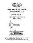
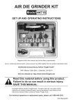
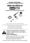
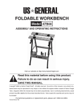
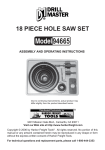
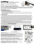
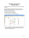
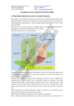
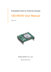
ROUTER TABLE INSERT
94331
ASSEMBLY AND OPERATING INSTRUCTIONS
3491 Mission Oaks Blvd., Camarillo, CA 93011
Visit our Web site at http://www.harborfreight.com
Copyright © 2006 by Harbor Freight Tools®. All rights reserved. No portion of this
manual or any artwork contained herein may be reproduced in any shape or
form without the express written consent of Harbor Freight Tools.
For technical questions and replacement parts, please call 1-800-444-3353
Specifications
Material
Molded phenolic plastic, steel accessories.
Dimensions
12” x 9” x 23/64 thick
Main Opening
3-7/8” inside demension
Guide Pin
1-3/8” L x 1/4” DIA. (pin) x 3/8” DIA. (shoulder)
Large Pop Out Ring
4-1/16” OD x 2-9/16” ID
Small Pop Out Ring
2-7/8” OD x 1-1/4” ID
Mounting Screws
6MM x 1.00, 15/64” long
Hex Key
3mm
Save This Manual
You will need the manual for the safety warnings and precautions, assembly instructions,
operating and maintenance procedures, parts list and diagram. Keep your invoice with this
manual. Write the invoice number on the inside of the front cover. Keep the manual and
invoice in a safe and dry place for future reference.
Safety Warnings and Precautions
WARNING: When using tools, basic safety precautions should always be followed to
reduce the risk of personal injury and damage to equipment.
Read all instructions before using this product! Follow all safety warnings and instructions provided by the manufacturers of the router being used.
1.
Keep work area clean. Cluttered areas invite injuries.
2.
Observe work area conditions. Do not use in damp or wet locations. Don’t expose
to rain. Keep work area well lighted. Do not use electrically powered tools in the
presence of flammable gases or liquids.
3.
Keep children away. Children must never be allowed in the work area. Do not let
them handle machines, tools, or extension cords.
4.
Store idle equipment. When not in use, tools must be stored in a dry location to
inhibit rust. Always lock up tools and keep out of reach of children.
5.
Use the right tool for the job. Do not attempt to force a small tool or attachment to
do the work of a larger industrial tool. There are certain applications for which this tool
was designed. It will do the job better and more safely at the rate for which it was
intended. Do not modify this tool and do not use this tool for a purpose for which it
was not intended.
6.
Dress properly. Do not wear loose clothing or jewelry as they can be caught in
moving parts. Protective, electrically non-conductive clothes and non-skid footwear
are recommended when working. Wear restrictive hair covering to contain long hair.
SKU 94331
Page 2
7.
Use eye, face and ear protection. Always wear ANSI approved impact safety
goggles. Wear a full face shield if you are producing metal filings or wood chips. Wear
an ANSI approved dust mask or respirator when working around metal, wood, and
chemical dusts and mists. Wearing work gloves is recommended.
8.
Do not overreach. Keep proper footing and balance at all times. Do not reach over or
across running machines.
9.
Maintain tools with care. Keep tools sharp and clean for better and safer
performance. Follow instructions for lubricating and changing accessories. Inspect tool
cords periodically and, if damaged, have them repaired by an authorized technician.
The handles must be kept clean, dry, and free from oil and grease at all times.
10.
Disconnect power. Unplug tool when not in use.
11.
Remove adjusting keys and wrenches. Check that keys and adjusting wrenches
are removed from the tool or machine work surface before plugging it in.
12.
Stay alert. Watch what you are doing, use common sense. Do not operate any tool
when you are tired.
13.
Take caution as some woods contain preservatives such as copper chromium
arsenate (CCA) which can be toxic. When cutting these materials extra care should
be taken to avoid inhalation and minimize skin contact.
14.
Check for damaged parts. Before using any tool, any part that appears damaged
should be carefully checked to determine that it will operate properly and perform its
intended function. Check for alignment and binding of moving parts; any broken parts
or mounting fixtures; and any other condition that may affect proper operation. Any
part that is damaged should be properly repaired or replaced by a qualified
technician. Do not use the tool if any switch does not turn On and Off properly.
15.
Guard against electric shock. Prevent body contact with grounded surfaces such as
pipes, radiators, ranges, and refrigerator enclosures.
16.
Replacement parts and accessories. When servicing, use only identical
replacement parts. Use of any other parts will void the warranty. Only use accessories
intended for use with this tool. Approved accessories are available from Harbor
Freight Tools.
17.
Do not operate tool if under the influence of alcohol or drugs. Read warning
labels on prescriptions to determine if your judgment or reflexes are impaired while
taking drugs. If there is any doubt, do not operate the tool.
18.
Pacemaker safety warning. People with pacemakers should consult with their
physician(s) before using this product; operation of equipment in close proximity to a
heart pacemaker could cause interference or failure of the pacemaker.
Warning: The warnings, cautions, and instructions discussed in this instruction manual
cannot cover all possible conditions and situations that may occur. It must be understood by the operator that common sense and caution are factors which cannot be
built into this product, but must be supplied by the operator.
SKU 94331
Page 3
Unpacking
When unpacking, check to make sure the following parts are included. Refer to the photo
below. If any parts are missing or broken, please call Harbor Freight Tools at the number on
the cover of this manual as soon as possible.
Parts List/Diagram
4 PC: Hold down magnets
1 PC: Phenolic plate
1 PC: Guide pin
2 PC: Snap out rings
1 PC: Hex key
4 PC: Mounting screws
PLEASE READ THE FOLLOWING CAREFULLY
THE MANUFACTURER AND/OR DISTRIBUTOR HAS PROVIDED THE PARTS DIAGRAM IN THIS MANUAL
AS A REFERENCE TOOL ONLY. NEITHER THE MANUFACTURER NOR DISTRIBUTOR MAKES ANY REPRESENTATION OR WARRANTY OF ANY KIND TO THE BUYER THAT HE OR SHE IS QUALIFIED TO MAKE
ANY REPAIRS TO THE PRODUCT OR THAT HE OR SHE IS QUALIFIED TO REPLACE ANY PARTS OF THE
PRODUCT. IN FACT, THE MANUFACTURER AND/OR DISTRIBUTOR EXPRESSLY STATES THAT ALL REPAIRS AND PARTS REPLACEMENTS SHOULD BE UNDERTAKEN BY CERTIFIED AND LICENSED TECHNICIANS AND NOT BY THE BUYER. THE BUYER ASSUMES ALL RISK AND LIABILITY ARISING OUT OF
HIS OR HER REPAIRS TO THE ORIGINAL PRODUCT OR REPLACEMENT PARTS THERETO, OR ARISING
OUT OF HIS OR HER INSTALLATION OF REPLACEMENT PARTS THERETO.
SKU 94331
Page 4
Router Table Insert Installation Instructions
Note: The table may need to be cut and routed to
accept this insert.
1. Decide how you want your router to be oriented in
relation to the table. We suggest that the handles
be aligned with the long dimension of the Table
Insert. You also should consider the location of the
switch, height adjustment knob & locking lever.
2. Be sure your Router Table Insert is in the proper
position, with the starting pin holes to the right of
the bit location.
3. Place your router upside down on top of the Router
Table Insert, with the router in the desired position.
You’ll be using the router baseplate as a drilling
template. Before removing the baseplate, put a
mark or piece of tape at the front and center of both
the baseplate and the Router Table Insert. These
will serve as reference points later on.
4. Next rmove the baseplate from the router and the
Router Table Insert from the table top.
5. Turn both plates upside down, and center the
router base plate on the Router Table Insert (the
concentric rings will help with this alignment).
Make sure the tape or marks you placed on the
plates in step #3 are oriented properly.
6. Clamp the Router Base Plate and the Router Table
Insert together securely.
7. Carefully drill through the table plate, using the
holes in the router base plate as guides.
8. Remove clamps, turn the table plate over and
countersink the holes you drilled in the previous
step. Run your countersink at slow speed, and use
care not to countersink too deep.
9. Mount the Router Table Insert to your router. If the
screws supplied with your router are too short, you
can obtain longer screws from hardware or automotive parts stores. Lower router and plate into
table and you’re ready to go!
SKU 94331
Page 5
Directions
1. The Guide Pin is used to create a starting position to push the stock material past the router
bit. (see photo below)
2. There are 4 magnets that are included with this package. These are use to level the Router
Table Insert on the table top. Place the magnets in the corners. They will adhere to the metal
screws under them or a steel router table .
3. The Pop Out Rings are used to accommodate different size router bits. (see photo below)
Warranty
LIMITED 1 YEAR
WARRANTY
Harbor Freight Tools Co. makes every effort to assure that its products meet high quality and durability standards,
and warrants to the original purchaser that this product is free from defects in materials and workmanship for
the period of 1 year from the date of purchase. This warranty does not apply to damage due directly or indirectly,
to misuse, abuse, negligence or accidents, repairs or alterations outside our facilities, or to lack of maintenance.
We shall in no event be liable for death, injuries to persons or property, or for incidental, contingent, special or
consequential damages arising from the use of our product. Some states do not allow the exclusion or limitation
of incidental or consequential damages, so the above limitation of exclusion may not apply to you. THIS
WARRANTY IS EXPRESSLY IN LIEU OF ALL OTHER WARRANTIES, EXPRESS OR IMPLIED, INCLUDING
THE WARRANTIES OF MERCHANTABILITY AND FITNESS.
To take advantage of this warranty, the product or part must be returned to us with transportation charges
prepaid. Proof of purchase date and an explanation of the complaint must accompany the merchandise. If our
inspection verifies the defect, we will either repair or replace the product at our election or we may elect to
refund the purchase price if we cannot readily and quickly provide you with a replacement. We will return
repaired products at our expense, but if we determine there is no defect, or that the defect resulted from
causes not within the scope of our warranty, then you must bear the cost of returning the product.
This warranty gives you specific legal rights and you may also have other rights which vary from state to state.
3491 Mission Oaks Blvd. • PO Box 6009 • Camarillo, CA 93011 • (800) 444-3353
SKU 94331
Page 6