1
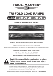
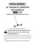
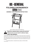
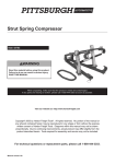
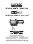
ALUMINUM LOADING RAMP
1200 LBS. CAPACITY
94057
ASSEMBLY & OPERATING INSTRUCTIONS
Diagrams within this manual may not be drawn proportionally.
Due to continuing improvements, actual product may differ slightly from the product described herein.
Distributed exclusively by Harbor Freight Tools®.
3491 Mission Oaks Blvd., Camarillo, CA 93011
Visit our website at: http://www.harborfreight.com
Read this material before using this product.
Failure to do so can result in serious injury.
Save this manual.
Copyright© 2005 by Harbor Freight Tools®. All rights reserved. No portion of this manual
or any artwork contained herein may be reproduced in any shape or form without the
express written consent of Harbor Freight Tools.
For technical questions or replacement parts, please call 1-800-444-3353.
THANK YOU for choosing a HARBOR FREIGHT TOOLS product. For future reference, please
complete the owner’s record below:
Model______________
Serial No._____________
Purchase Date_______________
SAVE THE RECEIPT, WARRANTY AND THESE INSTRUCTIONS. It is important that you read the
entire manual to become familiar with the unit BEFORE you begin assembly.
The Aluminum Loading Ramp can convert into a single load ramp or two single load ramps by
removing the hinges.
Technical Specifications
Construction:
Extruded Aluminum ridged platform and side railings
Overall Dimensions:
72” L x 30-1/4” W x 2-13/16” H
Angle Approach:
15-18 degree upward
Approach Length:
2-3/4”
Hinge Dimensions:
3-7/8” L x 3-1/8” W x 5/8” H x 3/32” Thick
Bolt Length:
4-3/8” x 5/16” Diameter
Hardness:
8.8 metric or Grade SAE 5
Chain (QTY = 2):
37” with 1-1/8” links, 0.155” OD. with “S” type hooks
Maximum Weight Capacity:
Rated at 1200 Lbs. (combined ramps, evenly distributed)
Net Weight:
34-1/2 Lbs.
Safety Warnings and Precautions
WARNING: When using product, basic safety precautions should always be followed to
reduce the risk of personal injury and damage to equipment.
Read all instructions before using this product!
1. Keep work area clean. Cluttered areas invite injuries.
2. Observe work area conditions. Keep work area well lighted.
3. Store idle equipment. When not in use, the Ramp must be stored in a safe and clean location.
Always lock up products and keep out of reach of children.
4.
Use the right product for the job. There are certain applications for which the Loading
Ramp was designed. Do not modify the Loading Ramp and do not use the Loading Ramp for a
purpose for which it was not intended.
5. Check for damaged parts. Before using any product, any part that appears damaged should
be carefully checked to determine that it will operate properly and perform its intended function.
Check for any broken or damaged parts and any other conditions that may affect its operation.
Replace or repair damaged or worn parts immediately. Note: Dents or other imperfections in
the Aluminum Ramp may lead to a weakening of the structural strength of this product; do not
use this ramp if this type of damage is noted.
6. Replacement parts and accessories. When servicing, use only identical replacement parts.
Use of any other parts will void the warranty.
SKU 94057
For technical questions, please call 1-800-444-3353.
REV 08e
Page 2
7. Do not operate product if under the influence of alcohol or drugs. Read warning labels on
prescriptions to determine if your judgment or reflexes are impaired while taking drugs. If there
is any doubt, do not operate the product.
8. Use eye protection. Always wear ANSI approved impact safety goggles during assembly.
9. Do not exceed the product’s maximum load capacity of 1200 Lbs (combined ramps).
10. Make proper ground contact. Only use on a flat, solid, dry surface capable of supporting
the Aluminum Ramp and its maximum capacity load of 1200 Lbs. (combined ramps).
Make certain that the tongue edge fully contacts the tailgate of the vehicle and that both safety
chains are secured in place.
11. Support the Ramp. Make certain that the Ramp Safety Chains are attached to the vehicle
before placing a load on the Ramp.
12. Dress properly. Do not wear loose clothing or jewelry as they can be caught in moving parts.
Non-Skid footwear is recommended when assembling and when using the Loading Ramp.
Wear restrictive hair covering to contain long hair.
13. Do not force this product. Do not use inappropriate attachments in an attempt to exceed the
ramp’s capacity.
14. Keep children away. Children must never be allowed in the work area.
15. Keep the Ramp clean. Prior to each use, clean dirt, oil, or any debris off the ramp.
16. Make certain that no persons or pets are under the Ramp or vehicle during loading.
17. Be aware of dynamic loading! If a weight drops onto or bounces on the Loading Ramp, it will
create, for a brief instant, an excess load, which may result in damage to the Ramp, the vehicle
and/or may result in personal injury.
18. Contact between the tongue of the Ramp and the tailgate of the vehicle, may result in
damage to the vehicle’s body finish.
19. Tailgate must be able to support the Loading Ramp and any vehicle or object loaded into
the vehicle.
20. Never attempt to drive one side of a four wheel vehicle up the ramp in order to use the
Ramp as a vehicle lifting device.
Warning: The warnings, cautions, and instructions discussed in this instruction manual cannot cover all possible conditions and situations that may occur. It must be understood by the operator that common sense and caution are factors which cannot be built into this product, but must be supplied by the operator.
Unpacking
When unpacking your Aluminum Loading Ramp, make certain that all parts on page 6 of this
manual are included. If any parts are missing or broken, please call HARBOR FREIGHT TOOLS at
1-800-444-3353.
SKU 94057
For technical questions, please call 1-800-444-3353.
Page 3
Operation
Your Aluminum Loading Ramp comes completely assembled. It is important that you read the entire
manual to become familiar with the product BEFORE you use the Loading Ramp.
Warning:
Warning:
Warning:
Warning:
All persons not involved in the loading process must stand clear of the
Loading Ramp. Especially keep children away. At least one assistant is
required to safely use this ramp.
Never exceed the 1200 Lb. maximum capacity (combined Ramps). Load the
vehicle slowly. Do not drive a load onto the vehicle.
Make certain the vehicle you are attaching the Loading Ramp to has its engine
off, its transmission in gear or park, and its emergency brake engaged.
Before attempting to use this product, make sure the Ramp is completely open
and both sides are laying flat on the tailgate and that the Safety Chains and
hooks are correctly in place.
Note: Walking up or down the Ramp is not recommended. If you must walk on the Ramp,
read and adhere to all safety warnings and instructions provided in this instruction manual.
1.
Make certain that the tailgate the Ramp will sit on is dry and clean. Set the tongue of the Ramp on the tailgate. The tailgate must be strong enough to support the Loading Ramp and any weight placed onto the Loading Ramp. Stretch the Chain (1) on each side of the Ramp up into the inside of the truck bed. Attach both Chains (1) to a secure location on the truck bed. Truck beds will usually have built in hooks or grommets for securing the Chain. The Chains (1) should be taut so that the Ramp’s tongue can not slip off of the tailgate-see Figure 1.
2.
Very slowly, push the vehicle that you wish to load up onto the Loading Ramp. Get help from
your assistant(s). Never sit on a vehicle while the vehicle is being moved up or down the
ramp.
Caution: If walking up or down the ramp, be extremely careful of your footing. Only walk on the innermost vertical beams. Never attempt to walk on the outside edge of the Ramp.
Figure 1
Chains (1)
Truck Bed
Aluminum Loading
Ramp
Secure Chains (1) to
hooks in vehicle
Set Loading Ramp tongue
securely on vehicle tailgate
Be extremely careful not to get your feet or fingers caught between the Left-Ramp (5)
and Right-Ramp (6).
SKU 94057
For technical questions, please call 1-800-444-3353.
Page 4
3.
Make sure no persons or pets are near or under the Ramp or vehicle. Have an assistant
monitor the Ramp tongue to make sure that no slippage occurs on the tailgate as you slowly
move the vehicle into the truck bed.
4.
When you are finished using the Loading Ramp, remove the Chain hooks from the truck bed
and carefully lift the Loading Ramp away from the truck bed.
Warning:
5.
Contact between the tongue of the Loading Ramp and the tailgate of the vehicle, may result in damage to the vehicle’s body finish.
After use, the Loading Ramp can be folded up. Make certain to lock the latches to secure
the two parts of the Ramp together. Wrap the safety chains around the ramp to secure
them. - see Figure 2.
Figure 3
Figure 2
Latch
Bolt (9)
Latch
Hinge (8)
Nut (10)
Converting the Aluminum Loading Ramp into Two Single Ramps
1.
To create two single ramps, separate the Left-Ramp (5) from the Right-Ramp (6).
Remove each of the three Bolts (9) and Nuts (10) from the Hinges (8) located in the center of the Ramp-see Figure 3. After removing the Bolts (9) and Nuts (10), you will have two single ramps.
2.
Note:
To assemble the Loading Ramp back into one single Loading Ramp, set the Left-Ramp (5)
and Right-Ramp (6) together with the holes in the Hinges (8) aligned as in Figure 3. Insert
a Bolt (9) through each Hinge (8) and thread on Nut (10).
When using as two single ramps, each single ramp Maximum weight capacity is
600 Lbs.
Maintenance
1.
Clean the Ramp after each use. Make certain any dirt, debris, oil or grease are cleaned off
the Ramp.
2.
Check the Ramp, Chain Rungs, and hinges for cracks, signs of stress, deformation,
or breakage. Do not use the Ramp if any faults are discovered. Take the Ramp to an
authorized service technician if repairs are required.
3.
Before each use, check each hinge Bolt (9) and Nut (10) for tightness.
SKU 94057
For technical questions, please call 1-800-444-3353.
REV 08e
Page 5
Parts List
Part #
1
2
3
4
5
Description
Chain
Bolt M6 x 40
Nut M6
Bolt M6 x 25
Left-Ramp
Quantity Part # Description
2
6
Right-Ramp
2
4
8
Hinge
2
9
Bolt
1
10
Nut
Quantity
1
3
3
3
Note: Some parts are listed and shown for illustration purposes only and are not available
individually as replacement parts.
PLEASE READ THE FOLLOWING CAREFULLY
THE MANUFACTURER AND/OR DISTRIBUTOR HAS PROVIDED THE PARTS DIAGRAM IN THIS MANUAL AS A REFERENCE TOOL
ONLY. NEITHER THE MANUFACTURER NOR DISTRIBUTOR MAKES ANY REPRESENTATION OR WARRANTY OF ANY KIND TO
THE BUYER THAT HE OR SHE IS QUALIFIED TO MAKE ANY REPAIRS TO THE PRODUCT OR THAT HE OR SHE IS QUALIFIED TO
REPLACE ANY PARTS OF THE PRODUCT. IN FACT, THE MANUFACTURER AND/OR DISTRIBUTOR EXPRESSLY STATES THAT ALL
REPAIRS AND PARTS REPLACEMENTS SHOULD BE UNDERTAKEN BY CERTIFIED AND LICENSED TECHNICIANS AND NOT BY THE
BUYER. THE BUYER ASSUMES ALL RISK AND LIABILITY ARISING OUT OF HIS OR HER REPAIRS TO THE ORIGINAL PRODUCT
OR REPLACEMENT PARTS THERETO, OR ARISING OUT OF HIS OR HER INSTALLATION OF REPLACEMENT PARTS THERETO.
Parts/Assembly Diagram
REV 08e
SKU 94057
For technical questions, please call 1-800-444-3353.
Page 6