1
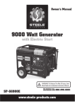
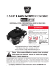
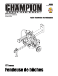
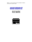
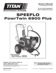
2” CLEAR WATER PUMP
5.5 HP - OVERHEAD VALVE ENGINE
Model 93662
ASSEMBLY AND OPERATING INSTRUCTIONS
Diagrams within this manual may not be drawn proportionally.
Due to continuing improvements, actual product may differ slightly from the product described herein.
Distributed exclusively by Harbor Freight Tools®.
3491 Mission Oaks Blvd., Camarillo, CA 93011
Visit our website at: http://www.harborfreight.com
Read this material before using this product.
Failure to do so can result in serious injury.
Save this manual.
Copyright© 2005 by Harbor Freight Tools®. All rights reserved. No portion of this
manual or any artwork contained herein may be reproduced in any shape or form
without the express written consent of Harbor Freight Tools.
For technical questions or replacement parts, please call 1-800-444-3353.
SPECIFICATIONS
Pump Type
Centrifugal / Requires Priming
Maximum Flow
145 GPM
Maximum Head Discharge
86 Feet
Maximum Suction Lift
26 Feet
Pump Speed
3600 RPM
Inlet/Outlet Size
2”
Engine
5.5 HP / Recoil Start
Air Cooled / 4-Stroke Overhead Valve / Single Cylinder
Engine Model: JF-168
Displacement: 163cc
Fuel Required: Unleaded Gasoline
Fuel Tank Capacity: 0.78 Gallons
Oil Capacity: 0.63 (Approx. 2/3) Quart
Operating Capacity: Approximately 2.8 Hours On Full Fuel Tank
EPA Compliant: (JDG-NRSI-04-02)
CARB Certification: (2004-CA S.I. SORE’s Compliant)
Accessories
2” Inlet Plastic Strainer / Wire Hose Clamps (Qty. 3) / Spark Plug Socket
2” x 2-1/2” Hose Adapters w/Screw On Caps & Washers (Qty. 2)
Net Weight
56 Pounds
The Emission Control System for this pump’s engine is warranted for standards set by the
U.S. Environmental Protection Agency and by the California Air Resources Board (also
known as CARB). For warranty information, refer to the back two pages of this manual.
SAVE THIS MANUAL
You will need this manual for the safety warnings and precautions, assembly, operating, inspection, maintenance and cleaning procedures, parts list and assembly diagram.
Keep your invoice with this manual. Write the invoice number on the inside of the front
cover. Keep this manual and invoice in a safe and dry place for future reference.
GENERAL SAFETY RULES AND PRECAUTIONS
WORK AREA
1.
Keep your work area clean and well lit. Cluttered benches and dark areas invite
accidents.
2.
Do not operate power tools in explosive atmospheres, such as in the
presence of flammable liquids, gases, or dust. Power tools create
sparks which may ignite the dust or fumes.
3.
Keep bystanders, children, and visitors away while operating a power tool.
Distractions can cause you to lose control. Protect others in the work area from
debris such as chips and sparks. Provide barriers or shields as needed.
SKU 93662
For technical questions, please call 1-800-444-3353.
Page 2
PERSONAL SAFETY
1.
Stay alert. Watch what you are doing, and use common sense when operating a power tool. Do not use a power tool while tired or under the influence
of drugs, alcohol, or medication. A moment of inattention while operating power
tools may result in serious personal injury.
2.
Dress properly. Do not wear loose clothing or jewelry. Contain long hair.
Keep your hair, clothing, and gloves away from moving parts. Loose clothes,
jewelry, or long hair can be caught in moving parts.
3.
Avoid accidental starting. Be sure the Power Switch (98A) is in its “OFF”
position before moving the Water Pump and before performing any service,
maintenance, or cleaning procedures on the unit.
4.
Remove adjusting keys or wrenches before turning the Water Pump on. A
wrench or a key that is left attached to a rotating part of the machine may result in
personal injury.
5.
Do not overreach. Keep proper footing and balance at all times. Proper footing
and balance enables better control of the power tool in unexpected situations.
6.
Use safety equipment. Always wear eye protection. Always wear ANSI
approved safety impact goggles when using this product. ANSI approved
hearing protection must also be used.
TOOL USE AND CARE
1.
Do not force the tool. Use the correct tool for your application. The correct tool
will do the job better and safer at the rate for which it is designed.
2.
Do not use the Water Pump if the Engine’s Power Switch (98A) does not turn
it on or off. Any tool that cannot be controlled with its power switch is dangerous
and must be replaced.
3.
Store idle tools out of reach of children and other untrained persons. Tools
are dangerous in the hands of untrained users.
4.
Maintain tools with care. Properly maintained tools with a sharp cutting edge
are less likely to bind and are easier to control. Do not use a damaged tool. Tag
damaged tools “Do not use” until repaired.
5.
Check for misalignment or binding of moving parts, breakage of parts, and any
other condition that may affect the tool’s operation. If damaged, have the tool
serviced before using. Many accidents are caused by poorly maintained tools.
6.
Use only accessories that are recommended by the manufacturer for your
model. Accessories that may be suitable for one tool may become hazardous
when used on another tool.
SKU 93662
For technical questions, please call 1-800-444-3353.
Page 3
SERVICE
1.
Tool service must be performed only by qualified repair personnel. Service or
maintenance performed by unqualified personnel could result in a risk of injury.
2.
When servicing a tool, use only identical replacement parts. Follow instructions in the “Inspection, Maintenance, And Cleaning” section of this manual.
Use of unauthorized parts or failure to follow maintenance instructions may create
a risk of electric shock or injury.
SPECIFIC SAFETY RULES AND PRECAUTIONS
1.
Your Warranty is voided if you do not put engine oil in the Engine’s crankcase
prior to its first use. Before each use, check the oil level. Never run the Engine
with low or no engine oil. Running the Engine with low or no oil will permanently
damage the unit.
2.
Maintain labels and nameplates on the Water Pump. These carry important
information. If unreadable or missing, contact Harbor Freight Tools for a replacement.
3.
Make sure the Water Pump is located on a flat, level, sturdy surface capable
of supporting the weight of the Water Pump and any additional tools and
equipment.
4.
Industrial applications must follow OSHA guidelines.
5.
Never stand on the Water Pump. Serious injury could result if the Water Pump
is tipped.
6.
Never leave the Water Pump unattended when it is running. Turn off the Engine
before leaving.
7.
Do not allow children and other unauthorized people to handle or play with
the Water Pump.
8.
Use this Water Pump outdoors only. Do not operate the Water Pump in a closed
area or in a poorly ventilated area. When running, the Engine of this Water Pump
produces carbon monoxide, a colorless, odorless, toxic fume that, when inhaled,
can cause serious personal injury or death.
9.
Do not force the Water Pump. This tool will do the work better and safer at the
speed and capacity for which it was designed.
FIRE AND EXPLOSION PRECAUTIONS
1.
Gasoline fuel and fumes are flammable, and potentially explosive. Use proper
fuel storage and handling procedures. Always have multiple ABC class fire extinguishers nearby.
SKU 93662
For technical questions, please call 1-800-444-3353.
Page 4
2.
Keep the Water Pump, its Engine, and surrounding areas clean at all times.
3.
When spills of fuel or oil occur, they must be cleaned up immediately. Dispose of fluids and cleaning materials as per any local, state, or federal codes and
regulations. Store oil rags in a covered metal container.
4.
Never store fuel or other flammable materials near the Water Pump.
5.
Do not smoke, or allow sparks, flames, or other sources of ignition around
the Water Pump.
6.
Keep grounded conductive objects, such as tools, away from exposed, live
electrical parts and connections to avoid sparking or arcing. These events
could ignite fumes or vapors.
7.
Do not refill the Fuel Tank while the Engine is running or while the Engine is
still hot. Do not operate the Water Pump with known leaks in the fuel system.
8.
Use only Engine manufacturer recommended fuel and oil.
MECHANICAL PRECAUTIONS
1.
Prior to performing service, maintenance, or cleaning procedures, always
make sure the Engine’s Power Switch (98A) is in its “OFF” position. Allow
the Engine and Water Pump to completely cool. Then, remove the spark plug
from the Engine.
2.
Do not alter or adjust any part of the Water Pump or Engine that is assembled
and supplied by the manufacturer.
3.
Always follow and complete scheduled Water Pump and Engine maintenance.
CHEMICAL PRECAUTIONS
1.
Avoid contact with hot fuel, oil, exhaust fumes, and solid surfaces.
2.
Avoid body contact with fuels, oils, and lubricants used in the Water Pump
and Engine. If swallowed, seek medical treatment immediately. Do not induce
vomiting if fuel is swallowed. For skin contact, immediately wash with soap and
water. For eye contact, immediately flush eyes with clean water.
NOISE PRECAUTION
Prolonged exposure to noise levels above 85 dBA is hazardous to hearing.
Always wear ANSI approved hearing protection when operating or working around
the Water Pump when it is running.
SKU 93662
For technical questions, please call 1-800-444-3353.
Page 5
MISC. PRECAUTIONS
1.
WARNING: The brass components of this product contain lead, a chemical
known to the State of California to cause birth defects (or other reproductive
harm). (California Health & Safety code § 25249.5, et seq.)
2.
People with pacemakers should consult their physician(s) before use. Electromagnetic fields in close proximity to heart pacemaker could cause pacemaker
interference or pacemaker failure. Caution is necessary when near engine’s magneto or recoil starter.
3.
WARNING! The warnings and precautions discussed in this manual cannot cover
all possible conditions and situations that may occur. It must be understood by the
operator that common sense and caution are factors which cannot be built into this
product, but must be supplied by the operator.
SAVE THESE INSTRUCTIONS
UNPACKING
When unpacking, check to make sure all the parts shown on the Parts Lists on
pages 14 and 15 are included. If any parts are missing or broken, please call Harbor
Freight Tools at the number shown on the cover of this manual as soon as possible.
SKU 93662
For technical questions, please call 1-800-444-3353.
Page 6
ASSEMBLY INSTRUCTIONS
CAUTION! Always make sure the Power Switch (98A) of the Engine is in its “OFF”
position prior to performing any service, maintenance, or cleaning of the Water
Pump or Engine.
To Add Engine Oil:
1.
IMPORTANT! Prior to first using the Water Pump, the Engine MUST be filled with
a high quality 10W-30 grade engine oil. (See Figure A.)
OIL DIPSTICK (65A)
MAXIMUM OIL LEVEL
MINIMUM OIL LEVEL
FIGURE A
2.
To do so, unscrew and remove the Engine Oil Dipstick (65A). Pour approximately
2/3 quart of engine oil into the Dipstick Hole. Do not overfill. (See Figure A.)
3.
Clean the Oil Dipstick (65A). Then screw the Dipstick fully back into the Dipstick
Hole. Unscrew and remove the Oil Dipstick again, and observe the level of engine oil on the Dipstick. The oil level should appear between the “MINIMUM” and
“MAXIMUM” indicator marks on the Oil Dipstick. (See Figure A.)
4.
If necessary, continue adding engine oil, while rechecking the Oil Dipstick (65A),
until the oil level reaches the “MAXIMUM” indicator on the Oil Dipstick.
Do not exceed the “MAXIMUM” indicator mark on the Oil Dipstick.
(See Figure A.)
When finished adding engine oil, carefully screw the Oil Dipstick (65A) back into
the Dipstick Hole. (See Figure A.)
5.
SKU 93662
For technical questions, please call 1-800-444-3353.
Page 7
To Fill The Fuel Tank:
FUEL TANK CAP
(83A)
FUEL TANK
(84A)
FIGURE B
1.
Prior to first using the Water Pump, the Fuel Tank (84A) MUST be filled with high
octane unleaded gasoline. (See Figure B.)
2.
To do so, remove the Fuel Tank Cap (83A) and fill the Fuel Tank with unleaded
gasoline. Then, replace the Fuel Tank Cap. Thereafter, check the Fuel Tank (84A)
for the amount of unleaded gasoline. When necessary, refill the Fuel Tank.
(See Figure B.)
To Connect An Intake Hose & Discharge Hose To The Water Pump:
1.
The Intake Filter (21) that is provided with the Water Pump should be attached to
the end of the Intake Hose (not included) with a Hose Clamp that is provided with
the Intake Union Set (9). (See Figure C, next page.)
2.
To connect the other end of the Intake Hose to the Water Pump, slide the Coupling
Gasket onto the Hose Coupling of the Intake Union Set (9). Slide the Hose Clamp
and Hose Joint of the Intake Union Set (9) onto the end of the Intake Hose. Insert
the Intake Hose onto the Hose Coupling, and firmly tighten the Hose Clamp to
secure the Intake Hose onto the Hose Coupling. Then, screw the Hose Joint onto
the Intake Flange (14) of the Water Pump. (See Figure C.)
3.
To connect a 2” diameter Discharge Hose (not included) to the Water Pump, slide
the Coupling Gasket onto the Hose Coupling of the Discharge Union Set (9). Slide
the Hose Clamp and Hose Joint of the Discharge Union Set (9) onto the end of the
Discharge Hose. Insert the Discharge Hose onto the Hose Coupling, and firmly
tighten the Hose Clamp to secure the Discharge Hose onto the Hose Coupling.
Then, screw the Hose Joint onto the Discharge Flange (10) of the Water Pump.
(See Figure C.)
SKU 93662
For technical questions, please call 1-800-444-3353.
Page 8
HOSE
COUPLING
HOSE
JOINT
COUPLING
GASKET
HOSE
COUPLING
HOSE
CLAMP
HOSE
JOINT
COUPLING
GASKET
HOSE
CLAMP
2” DIAMETER
INTAKE HOSE
(NOT INCLUDED)
HOSE
CLAMP
INTAKE
FILTER
(21)
2” DIAMETER
DISCHARGE HOSE
(NOT INCLUDED)
DISCHARGE FLANGE
(10)
INTAKE FLANGE
(14)
FIGURE C
SKU 93662
For technical questions, please call 1-800-444-3353.
Page 9
OPERATING INSTRUCTIONS
To Properly Locate The Water Pump:
1.
WARNING! Use this Water Pump outdoors only. Do not operate the Water
Pump in a closed area or in a poorly ventilated area. When running, the Engine
of this Water Pump produces carbon monoxide, a colorless, odorless, toxic
fume that, when inhaled, can cause serious personal injury or death.
2.
Keep your work area clean and well lit. Cluttered and dark areas invite accidents.
3.
Do not operate the Water Pump in explosive atmospheres, such as
in the presence of flammable liquids, gases, or dust. The Water Pump
and its Engine can create sparks which may ignite the dust or fumes.
4.
Make sure the Water Pump is located on a flat, level, sturdy surface capable of supporting the weight of the Water Pump and any additional tools and equipment.
5.
Route the Intake Hose with its Intake Filter (21) fully immersed in the water supply
source. Then, make sure to secure the Intake Hose in place to keep it from moving once the Water Pump is turned on. NOTE: The maximum suction lift of the
Water Pump is 26 feet. The Intake Hose should be kept as short as possible for
more efficient operation.
6.
Route the Discharge Hose to the desired discharge location. If necessary, connect
additional Discharge Hoses to direct the discharge to the desired location. Then,
secure the Discharge Hose in place to keep it from moving once the Water Pump
is turned on.
Note: The maximum discharge length of the Water Pump is 86 feet. The Discharge Hose
should be kept as short as possible for more efficient operation.
To Prime The Water Pump:
1.
The Water Pump MUST be primed with clean water prior to each use of the Pump.
To Prime the Water Pump, unscrew and remove the Priming Cap (11) located at
the top of the Discharge Flange (10). (See Figure D, next page.)
2.
Fill the Discharge Flange (10) to its top with clean water. Then, replace the
Priming Cap (11). (See Figure D.)
SKU 93662
For technical questions, please call 1-800-444-3353.
Page 10
PRIMING CAP (11)
DISCHARGE FLANGE (10)
FIGURE D
To Start And Stop The Engine:
Note: Only use this pump to pump unheated clean water. Other liquids may damage the
pump and/or be hazardous.
1.
Once the Engine is started, the Water Pump will run continuously until the Engine
is turned off.
2.
When finished using the Water Pump, turn off the Engine. Make sure to allow the
Water Pump and its Engine to completely cool before moving the Water Pump or
storing the unit.
REV 06j, 07f
SKU 93662
For technical questions, please call 1-800-444-3353.
Page 11
INSPECTION, MAINTENANCE, AND CLEANING
1.
CAUTION! Always make sure the Power Switch (98A) of the Engine is in its “OFF”
position prior to performing any service, maintenance, or cleaning of the Water
Pump or Engine.
2.
Before each use, inspect the general condition of the Water Pump. Check for loose
screws, misalignment or binding of moving parts, cracked or broken parts, loose
hose connections, and any other condition that may affect the safe operation of the
Water Pump. If abnormal noise or vibration occurs, have the problem corrected
before further use.
Do not use damaged equipment.
3.
Before each use, check the Engine oil level in the Engine. If necessary, fill the
crankcase of the Engine with the proper amount and type of engine oil.
4.
Before each use, check the Inlet Filter (21) for accumulated debris, rocks, and
other objects that may clog the Inlet Filter.
5.
If the Water Pump is not in use due to dry conditions, etc., prime the Water
Pump and activate the unit once every three months.
6.
In cold weather, when if the Water Pump is not in use, protect the interior of the
Pump from freezing by draining any remaining water and pumping a permanent
type automotive antifreeze containing a rust inhibitor through the system. A 50%
mixture with clean water is recommended. Make sure to flush the system with a
neutralizing liquid prior to reuse of the unit.
7.
To clean the Water Pump, use a garden hose and a mild detergent. Avoid introducing water into the interior parts of the Engine.
8.
When storing the Water Pump, make sure to store the unit in a clean, dry, safe
location out of reach of children and other unauthorized people.
9.
Engine maintenance: Refer to the Engine manufacturer’s manual for complete
inspection, maintenance, and cleaning instructions.
10.
CAUTION! All maintenance, service, or repairs not mentioned in this manual
must only be performed by a qualified service technician.
SKU 93662
For technical questions, please call 1-800-444-3353.
Page 12
TROUBLESHOOTING
1. Take the engine to a
qualified service technician.
NOTE: If the water pump still does not operate
properly, take the pump to a qualified service technician.
PLEASE READ THE FOLLOWING CAREFULLY
THE MANUFACTURER AND/OR DISTRIBUTOR HAS PROVIDED THE PARTS LIST AND
ASSEMBLY DIAGRAM IN THIS MANUAL AS A REFERENCE TOOL ONLY. NEITHER THE
MANUFACTURER OR DISTRIBUTOR MAKES ANY REPRESENTATION OR WARRANTY
OF ANY KIND TO THE BUYER THAT HE OR SHE IS QUALIFIED TO REPLACE ANY PARTS
OF THE PRODUCT. IN FACT, THE MANUFACTURER AND/OR DISTRIBUTOR EXPRESSLY
STATES THAT ALL REPAIRS AND PARTS REPLACEMENTS SHOULD BE UNDERTAKEN BY
CERTIFIED AND LICENSED TECHNICIANS, AND NOT BY THE BUYER. THE BUYER ASSUMES ALL RISKS AND LIABILITY ARISING OUT OF HIS OR HER REPAIRS TO THE ORIGINAL PRODUCT OR REPLACEMENT PARTS THERETO, OR ARISING OUT OF HIS OR HER
INSTALLATION OF REPLACEMENT PARTS THERETO.
SKU 93662
For technical questions, please call 1-800-444-3353.
Page 13
PARTS LIST & ASSEMBLY DIAGRAM - WATER PUMP
Part
1
2
3
4
5
6
7
8
9
10
11
12
Description
Cover
Hex Bolt
O-Ring
Mechanical Seal
Impeller
Casing
Pump Housing
Discharge Packing
Intake/Discharge Union Set
Discharge Flange
Priming Cap
Bolt
Qty.
1
1
4
1
1
1
1
1
1 ea.
2
1
9
Part
13
14
15
3#
3#-1
16
17
18
19
20
21
Description
Washer
Intake Flange
Check Valve
O-Ring
O-Ring
Tube Frame
Screw
Oscillation Absorber
Bolt
Gasoline Engine
Intake Filter
Qty.
9
1
1
1
2
1
8
4
4
1
1
21
Note: Some parts are listed and shown for illustration purposes only, and are not available
individually as replacement parts.
SKU 93662
For technical questions, please call 1-800-444-3353.
Page 14
PARTS LIST - ENGINE
Part
2A
3A
4A
5A
6A
7A
8A
9A
10A
11A
12A
13A
14A
15A
16A
17A
18A
19A
20A
21A
22A
23A
24A
25A
26A
27A
28A
29A
30A
31A
32A
33A
34A
35A
36A
37A
38A
39A
40A
41A
42A
43A
44A
45A
46A
47A
48A
49A
50A
Description
Cylinder Head Bolt
Cylinder Head Cover Bolt
Cylinder Head Cover
Lock Nut
Adjusting Screw
Rocker Arm
Rocker Arm Bolt
Valve Push Rod Guiding Board
Valve Push Rod
Cylinder Head
Carburetor Shield
Carburetor Packing
Carburetor Assembly
Air Cleaner Case
Air Cleaner Seal
Bolt (M6)
Air Cleaner Cover
Air Cleaner Element
Air Cleaner Separator
Choke Lever
Carburetor Packing II
Stud Bolt (M6-109)
Intake Valve
Exhaust Valve
Cylinder Head Gasket
Exhaust Pipe Stud
Spark Plug
Valve Guide
Valve Spring
Rocker Shaft Circlip
Anti-Wear Valve Stem Protector
Cylinder Head Cover Packing
Governor Spring
Bolt
High Tension Line
Ignition Coil
Nut (Special 14mm)
Starter Ratchet Spring
Start Rope
Start Handle
Starting Case Assembly
Spiral Spring
Starting Wheel
Circlip
Starting Ratchet
Friction Plate Screw
Cover
Starter Pulley
Cooling Fan
Qty.
4
4
1
2
2
3
2
1
2
1
1
1
1
1
1
4
1
1
1
1
1
2
1
1
1
2
1
2
2
2
2
1
1
1
1
1
1
2
1
1
1
1
1
1
2
1
1
1
1
Part
51A
52A
53A
54A
55A
56A
57A
58A
59A
60A
61A
62A
63A
64A
65A
66A
67A
68A
69A
70A
71A
72A
73A
74A
75A
76A
77A
78A
79A
80A
81A
82A
83A
84A
85A
86A
87A
88A
89A
90A
91A
92A
93A
94A
95A
96A
97A
98A
Description
Flywheel Magneto
Cylinder Block
Speed Control Lever
Governor Arm
Governor Spring
Governor Support
Bolt (M6-15)
Oil Alert Nut
Plug (M10-15)
Plug Washer
Oil Alert
Bolt (M6)
Crankshaft
Crankshaft Gear
Oil Dipstick
Oil Dipstick Seal Ring
Gear Casing
Bolt (M8-35)
Gear Case Packing
Bearing
Camshaft Assembly
Locating Pin
Oil Seal
Connecting Rod Bolt
Connecting Rod Cap
Connecting Rod
Piston
Compression Ring 1
Compression Ring 2
Oil Scraper Ring
Piston Pin
Piston Pin Circlip
Fuel Tank Cap
Fuel Tank
Fuel Pipe
Fuel Pipe Protecting Tube
Fuel Filter
O-Ring
Fuel Valve
Bolt (M5-8)
Complete Outside Cover
Bolt (M5-8)
Bolt (M4-8)
Complete Silencer
Exhaust Filter Cartridge Assy.
Exhaust Pipe Packing
Bolt (M5-38)
Power Switch
Qty.
1
1
1
1
1
1
2
1
2
2
1
2
1
1
2
2
1
6
2
2
1
4
2
2
1
1
1
1
1
1
1
2
1
1
1
1
1
1
1
2
1
2
1
1
1
1
2
1
Engine Maintenance
The Spark Plug is LD(F7RTC), BPR6ES(NGK). The Spark Plug gap setting is 0.7--0.8mm. The Intake
Valve clearance is 0.15mm, Exhaust Valve clearance is 0.20mm. The valve clearance needs to be adjusted after 100 hours. Change the engine oil after 20 hours or internal one month.
SKU 93662
For technical questions, please call 1-800-444-3353.
Page 15
ASSEMBLY DIAGRAM - ENGINE
SKU 93662
For technical questions, please call 1-800-444-3353.
REV 08c
Page 16
Emission Control System Warranty
California and United States Emission Control Defects Warranty Statement
The California Air Resources Board (herein CARB), the United States Environmental Protection Agency (herein EPA), and Harbor Freight
Tools® (herein HFT) are pleased to explain the emission control system warranty on your 1995 and later Small Off-Road Engine (herein
engine). In California, the engine must be designed, built and equipped to meet the State’s stringent anti-smog standards. Elsewhere
within the United States, new off-road, spark-ignition engines certified for model year 1997 and later, must meet similar standards set
forth by the EPA. HFT must warrant the emission control system on your engine for the periods of time described below, provided
there has been no abuse, neglect or improper maintenance of your engine.
Your emission control system may include parts such as the carburetor or fuel-injection system, and the ignition system. Also included
may be hoses, belts, connectors and other emission-related assemblies.
Where a warrantable condition exists, HFT will repair your engine at no cost to you including diagnosis, parts and labor.
Manufacturer’s Warranty Coverage
The 1995 and later engines are warranted for two (2) years. If any emission-related part on your engine is defective, the part will be
repaired or replaced by HFT.
Harbor Freight Tools Emission Control Defects Warranty Coverage
Engines are warranted for a period of two (2) years relative to emission control parts defects, subject to the provisions set forth below.
If any emission related part on your engine is defective, the part will be repaired or replaced by HFT.
Owner’s Warranty Responsibilities
- As the engine owner, you are responsible for the performance of the required maintenance listed in your Owner’s Manual. HFT
recommends that you retain all receipts covering maintenance on your engine, but HFT cannot deny warranty solely for the lack
of receipts or for your failure to ensure the performance of all scheduled maintenance.
- As the engine owner, you should, however, be aware that HFT may deny you warranty coverage if your engine or a part has failed
due to abuse, neglect, improper maintenance, or unapproved modifications.
- You are responsible for shipping your engine to a HFT warranty station as soon as a problem exists. Contact the HFT Customer
Service department at the number below to make shipping arrangements. The warranty repairs should be completed in a reasonable amount of time, not to exceed 30 days.
If you have any questions regarding your warranty rights and responsibilities, you should contact the Harbor Freight Tools Customer
Service Department at 1-800-444-3353.
Harbor Freight Tools Emission Control Defects Warranty Provisions
1. Length of Coverage
HFT warrants to a first retail purchaser and each subsequent purchaser that the engine is free from defects in materials and
workmanship that cause the failure of warranted parts for a period of two (2) years after the date of delivery to the first retail
purchaser.
2. No Charge Repair or Replacement
Repair or replacement of any warranted part will be performed at no charge to the owner if the work is performed through a warranty
station authorized by HFT. For emissions warranty service, contact the HFT Customer Service Department at 1-800-444-3353.
3. Consequential Damages Coverage
Coverage under this warranty shall also extend to the failure of any engine components caused by the failure of any warranted
part while it is still covered under this warranty.
4. Coverage Exclusions
Warranty claims shall be filed in accordance with the provisions of the HFT warranty policy explained in the box at the top of the
previous page. HFT shall not be liable for any loss of use of the engine, for any alternative usage, for any damage to goods, loss
of time, or inconvenience. Warranty coverage shall also be excluded for any part which fails, malfunctions, or is damaged due to
failure to follow the maintenance and operating instructions set forth in the Owner’s Manual including, but not limited to:
(a) use of parts which are not authorized by HFT
(b) improper installation, adjustment or repair of the engine or of any warranted part unless performed by an authorized warranty
center
(c) failure to follow recommendations on fuel use contained in the Owner’s Manual
(d) improper or inadequate maintenance of any warranted parts
(e) repairs performed outside of the authorized warranty service dealers
(f) alterations by changing, adding to or removing parts from the engine.
SKU 93662
For technical questions, please call 1-800-444-3353.
Page 17
Emission Control System Warranty - continued
Harbor Freight Tools Emission Control Defects Warranty Provisions
5. Service and Maintenance
Component parts which are not scheduled for replacement as required maintenance or are scheduled only for regular inspection
to the effect of “repair or replace as necessary” are warranted for the warranty period. Any warranted part which is scheduled
for replacement as required maintenance is warranted for the period of time up to the first scheduled replacement point for that
part. Any replacement part, provided it is equivalent in durability and performance, may be used in performance of maintenance
or repairs. The owner is responsible for commissioning a qualified technician/mechanic to perform all required maintenance, as
outlined in the Inspection, Cleaning, and Maintenance section on page 17 of this manual.
6. Warranted Parts
1) Fuel Metering System
i)
ii)
Carburetor and its internal parts.
Fuel pump (if so equipped).
iii) Cold start enrichment system.
2) Air Induction System
i)
Intake pipe/manifold.
ii)
Air cleaner.
3) Ignition System
i)
Spark plug.
ii)
Magneto ignition system.
4) Catalyst System (if so equipped)
i)
ii)
Exhaust pipe stud.
Muffler.
iii) Catalytic converter (if so equipped).
5) Miscellaneous items Used in Above Systems
i)
ii)
Vacuum, temperature and time sensitive valves and switches.
Hoses, belts, connectors, and assemblies.
Pump Performance Flow Chart
SKU 93662
For technical questions, please call 1-800-444-3353.
Page 18