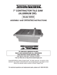
1
2.5 HP AIR COMPRESSOR
29 GALLON CAPACITY
Model 93351
ASSEMBLY AND OPERATING INSTRUCTIONS
WARNING!
Your Warranty Is Voided If:
A. You do not put compressor oil in the Compressor’s crankcase prior to its first use.
Before each use, check the oil level. Never run the Compressor with low or no compressor oil. Running the Compressor with low or no oil will permanently damage the unit.
B. You use an extension cord with the Air Compressor.
Connect the Air Compressor’s Power Cord Plug directly to the nearest 120 volt, grounded,
electrical outlet. If necessary, attach a longer air hose to the Compressor.
C. You drop the Air Compressor.
Do not lift the Air Compressor using its Handle.
Do to continuing improvements,
actual product may differ slightly
from the product described herein.
®
3491 Mission Oaks Blvd., Camarillo, CA 93011
Visit our Web site at: http://www.harborfreight.com
TO PREVENT SERIOUS INJURY,
READ AND UNDERSTAND ALL WARNINGS
AND INSTRUCTIONS BEFORE USE.
Copyright© 2005 by Harbor Freight Tools®. All rights reserved. No portion of this
manual or any artwork contained herein may be reproduced in any shape or form
without the express written consent of Harbor Freight Tools.
For technical questions, please call 1-800-444-3353.
Cover Revised 05/06
PRODUCT SPECIFICATIONS
Electrical Requirements
120V / 60 Hz / Single Phase / 13.5 Amps (With Load)
2.5 HP / Single Phase / 3450 RPM
3-Wire Power Cord (6’ Long x 16 Gauge x 3 Cords)
3-Prong Power Cord Plug
Air Tank Capacity
29 Gallons
Pump Stage
Single Stage (Direct Drive)
Pump Style
Single Cylinder Pump
Maximum Air Pressure
110 PSI w/Automatic Shut Off
Auto Start PSI
Starts at 85 PSI
Regulators w/Gauges
Reads 0-200 PSI (in 10 PSI Increments)
Air Flow Capacity
8.5 CFM @ 40 PSI / 7.5 CFM @ 90 PSI
Air Outlet Size
¼”-18 NPT
Accessories
Air Filter (Qty. 1)
Tool Weight
154 Pounds
SAVE THIS MANUAL
You will need this manual for the safety warnings and precautions, assembly, operating,
inspection, maintenance and cleaning procedures, parts list and assembly diagram. Keep
your invoice with this manual. Write the invoice number on the inside of the front cover.
Keep this manual and invoice in a safe and dry place for future reference.
GENERAL SAFETY RULES
WARNING!
READ AND UNDERSTAND ALL INSTRUCTIONS
Failure to follow all instructions listed below may result in
electric shock, fire, and/or serious injury.
SAVE THESE INSTRUCTIONS
WORK AREA
1.
Keep your work area clean and well lit. Cluttered benches and dark areas invite
accidents.
2.
Do not operate power tools in explosive atmospheres, such as in the
presence of flammable liquids, gases, or dust. Power tools create sparks
which may ignite the dust or fumes.
3.
Keep bystanders, children, and visitors away while operating a power tool
Distractions can cause you to lose control. Protect others in the work area from
debris such as chips and sparks. Provide barriers or shields as needed.
SKU 93351
For technical questions, please call 1-800-444-3353.
Page ELECTRICAL SAFETY
1.
Grounded tools must be plugged into an outlet properly installed and
grounded in accordance with all codes and ordinances. Never remove
the grounding prong or modify the plug in any way. Do not use any
adapter plugs. Check with a qualified electrician if you are in doubt as to
whether the outlet is properly grounded. If the tools should electrically malfunction or break down, grounding provides a low resistance path to carry electricity
away from the user.
5.
Double insulated tools are equipped with a polarized plug (one blade is wider
than the other). This plug will fit in a polarized outlet only one way. If the plug
does not fit fully in the outlet, reverse the plug. If it still does not fit, contact
a qualified electrician to install a polarized outlet. Do not change the plug
in any way. Double insulation
eliminates the need for the three wire grounded
power cord and grounded power supply system.
6.
Avoid body contact with grounded surfaces such as pipes, radiators, ranges,
and refrigerators. There is an increased risk of electric shock if your body is
grounded.
7.
Do not expose power tools to rain or wet conditions. Water entering a power tool will increase the risk of electric shock.
8.
Do not abuse the Power Cord. Never use the Power Cord to carry the tools or
pull the Plug from an outlet. Keep the Power Cord away from heat, oil, sharp
edges, or moving parts. Replace damaged Power Cords immediately. Damaged Power Cords increase the risk of electric shock.
PERSONAL SAFETY
9.
Stay alert. Watch what you are doing, and use common sense when operating a power tool. Do not use a power tool while tired or under the influence
of drugs, alcohol, or medication. A moment of inattention while operating power
tools may result in serious personal injury.
10.
Dress properly. Do not wear loose clothing or jewelry. Contain long hair.
Keep your hair, clothing, and gloves away from moving parts. Loose clothes,
jewelry, or long hair can be caught in moving parts.
11.
Avoid accidental starting. Be sure the ON/OFF Knob (86) is off before plugging in. Plugging in power tools with the ON/OFF Knob on, invites accidents.
12.
Remove adjusting keys or wrenches before turning the power tool on. A wrench or
a key that is left attached to a rotating part of the power tool may result in personal
injury.
SKU 93351
For technical questions, please call 1-800-444-3353.
Page 13.
Do not overreach. Keep proper footing and balance at all times. Proper footing
and balance enables better control of the power tool in unexpected situations.
14.
Use safety equipment. Always wear eye protection. Always wear ANSI approved safety impact goggles when using this product. Hearing protection must be used for appropriate conditions.
TOOL USE AND CARE
15.
Use clamps (not included) or other practical ways to secure and support the workpiece to a stable platform. Holding the work by hand or against your body is unstable and may lead to loss of control.
16.
Do not force the tool. Use the correct tool for your application. The correct
tool will do the job better and safer at the rate for which it is designed.
17.
Do not use the power tool if the ON/OFF Knob (86) does not turn it on or off.
Any tool that cannot be controlled with the Power Switch is dangerous and must
be replaced.
18.
Disconnect the Power Cord Plug from the power source before making any
adjustments, changing accessories, or storing the tool. Such preventive safety
measures reduce the risk of starting the tool accidentally.
19.
Store idle tools out of reach of children and other untrained persons. Tools are dangerous in the hands of untrained users.
20.
Maintain tools with care. Keep cutting tools sharp and clean. Properly maintained tools with a sharp cutting edge are less likely to bind and are easier to control.
Do not use a damaged tool. Tag damaged tools “Do not use” until repaired.
21.
Check for misalignment or binding of moving parts, breakage of parts, and any
other condition that may affect the tool’s operation. If damaged, have the tool
serviced before using. Many accidents are caused by poorly maintained tools.
22.
Use only accessories that are recommended by the manufacturer for your
model. Accessories that may be suitable for one tool may become hazardous
when used on another tool.
SERVICE
23.
Tool service must be performed only by qualified repair personnel. Service or maintenance performed by unqualified personnel could result in a risk of injury
24.
When servicing a tool, use only identical replacement parts. Follow instructions in the “Inspection, Maintenance, And Cleaning” section of this
manual. Use of unauthorized parts or failure to follow maintenance instructions
may create a risk of electric shock or injury.
SKU 93351
For technical questions, please call 1-800-444-3353.
Page SPECIFIC SAFETY RULES
1.
WARNING! Your Warranty is voided if:
a. You do not put compressor oil in the Compressor’s crankcase prior to its
first use. Before each use, check the oil level. Never run the Compressor
with low or no compressor oil. Running the Compressor with low or no
oil will permanently damage the unit.
b. You use an extension cord with the Air Compressor. Connect the Air
Compressor’s Power Cord Plug directly to the nearest 120 volt, grounded,
electrical outlet. If necessary, attach a longer air hose to the Compressor.
c. You drop the Air Compressor. Do not lift the Air Compressor using its
Handle.
2.
This Air Compressor may require a dedicated electrical circuit, as the amperage draw under full load combined with use of any other item may overload
your circuit.
3.
Maintain labels and nameplates on the Air Compressor. These carry important
information. If unreadable or missing, contact Harbor Freight Tools for a replacement.
4.
Always wear ANSI-approved safety impact eye goggles when assembling and
using the Air Compressor.
5.
Maintain a safe working environment. Keep the work area well lit. Make sure
there is adequate surrounding workspace. Always keep the work area free of obstructions, grease, oil, trash, and other debris.
6.
DANGER! This Air Compressor is NOT equipped and should not be used “as is”
to supply breathing quality air. For any application of air for human consumption,
you must fit the Air Compressor with suitable inline safety and alarm equipment
(not included). This additional equipment is necessary to properly filter and purify
the air to meet minimal specifications for Grade D breathing as described in Compressed Gas Association Commodity Specification G 7.1-1966, OSHA 29 CFR
1910. 134, and/or Canadian Standards Associations (CSA). In the event the Air
Compressor is used for the purpose of breathing air application and proper inline
safety and alarm equipment is not simultaneously used, existing warranties are void,
and Harbor Freight Tools disclaims any liability whatsoever for any loss, personal
injury, or damage.
7.
DANGER! Never attempt to repair or modify the Tank (50). Welding, drilling, or
any other modification will weaken the Tank resulting in damage from rupture or
explosion. Always replace worn, cracked, or damaged Tanks.
SKU 93351
For technical questions, please call 1-800-444-3353.
Page 8.
WARNING! Never use plastic (PVC) pipe for compressed air. Serious injury or death
could result. Any tube, pipe, or hose used must have a pressure rating higher than
150 PSI. Minimum recommended pipe size: Up to 50 feet long use 1/2” diameter.
Greater than 50 feet use 3/4” diameter. Larger diameter pipe is always better.
9.
This Air Compressor is not designed for outdoor use.
10.
WARNING! This Air Compressor is extremely top heavy. The unit must be bolted
to the floor with isolation pads (not included) or secured with a wall cable (not included) before operating to prevent equipment damage, injury, or death.
(See Illustration Below.)
WALL CABLE
(NOT INCLUDED)
ISOLATION PAD
(NOT INCLUDED)
WALL CABLE
(NOT INCLUDED)
ISOLATION PAD
(NOT INCLUDED)
11.
Make sure all tools and equipment used with the Air Compressor are rated to
the appropriate capacity. Do not use any tool or equipment that does not operate
from 85 PSI to 110 PSI.
12.
Drain the Air Compressor every day. Do not allow excessive moisture to build
up inside the Air Compressor’s Tank.
13.
Avoid injury. Never direct the Air Outlet Valve at people or animals.
14.
Do not alter or remove the Safety Valve (67). Do not open the Pressure Switch
Box (66).
15.
Do not handle the ON/OFF Knob (86) or Power Cord Plug with wet hands.
16.
Make sure the Air Compressor is located on a flat, level, sturdy surface capable
of supporting the weight of the Compressor, operator(s), and any additional
tools and equipment.
17.
Keep all electrical connections dry and off the ground.
18.
Industrial applications must follow OSHA guidelines.
SKU 93351
For technical questions, please call 1-800-444-3353.
REV 05/06
Page 19.
Never stand on the Air Compressor. Serious injury could result if the Compressor is tipped.
20.
Never leave the Air Compressor unattended when it is plugged in and running.
Turn off the Compressor, and unplug the unit before leaving.
21.
Do not allow children and other unauthorized people to handle or play with
the Air Compressor.
22.
Always turn off the Air Compressor and unplug it from its electrical outlet
before performing any inspection, maintenance, or cleaning.
23.
WARNING! This product contains brass, which is a chemical known to the State of
California to cause cancer and birth defects and other reproductive harm. (California
Health & Safety Code 25249.5, et seq.)
24.
WARNING! People with pacemakers should consult their physician(s) before using
this product. Operation of electrical equipment in close proximity to a heart pacemaker could cause interference to or failure of the pacemaker.
25.
WARNING! The warnings and cautions discussed in this manual cannot cover all
possible conditions and situations that may occur. It must be understood by the
operator that common sense and caution are factors which cannot be built into this
product, but must be supplied by the operator.
SAVE THESE INSTRUCTIONS
To extend the life of your tools and equipment, it is recommended that you install an oiler and water filter inline with the air output line of the Air Compressor. (See Figure A.)
REGULATOR
FIGURE A
SKU 93351
WATER
FILTER
OILER
For technical questions, please call 1-800-444-3353.
Page GROUNDING
WARNING!
Improperly connecting the grounding wire can result in the risk of electric shock.
Check with a qualified electrician if you are in doubt as to whether the outlet is
properly grounded. Do not modify the power cord plug provided with the tool.
Never remove the grounding prong from the plug. Do not use the tool if the power
cord or plug is damaged. If damaged, have it repaired by a service facility before
use. If the plug will not fit the outlet, have a proper outlet installed by a qualified
electrician.
GROUNDED TOOLS: TOOLS WITH THREE PRONG PLUGS
1.
Tools marked with “Grounding Required” have a three wire cord and three prong grounding plug. The plug must be connected to a properly grounded outlet. If the tool should electrically malfunction or break down, grounding provides a low resistance path to carry electricity away from the user, reducing the risk of electric shock. (See Figure B, next page.)
2.
The grounding prong in the plug is connected through the green wire inside the cord to the grounding system in the tool. The green wire in the cord must be the only wire connected to the tool’s grounding system and must never be attached to an electrically “live” terminal. (See Figure B.)
3.
Your tool must be plugged into an appropriate outlet, properly installed and grounded in accordance with all codes and ordinances. The plug and outlet should look like those in the following illustration. (See Figure B.)
THIS PRODUCT
USES A
3-PRONG PLUG
120 VOLT,
GROUNDED,
ELECTRICAL OUTLET
FIGURE B
SKU 93351
For technical questions, please call 1-800-444-3353.
Page DOUBLE INSULATED TOOLS: TOOLS WITH TWO PRONG PLUGS
4.
5.
Tools marked “Double Insulated” do not require grounding. They have a special double insulation system which satisfies OSHA requirements and complies with the applicable standards of Underwriters Laboratories, Inc., the Canadian
Standard Association, and the National Electrical Code. (See Figure C.)
Double insulated tools may be used in either of the 120 volt outlets shown in the following illustration. (See Figure C.)
120 VOLT,
GROUNDED,
ELECTRICAL OUTLET
120 VOLT,
GROUNDED,
ELECTRICAL OUTLET
FIGURE C
SYMBOLOGY
Double Insulated
Canadian Standards Association
Underwriters Laboratories, Inc.
V~
A
n0 xxxx/min.
SKU 93351
Volts Alternating Current
Amperes
No Load Revolutions per Minute (RPM)
For technical questions, please call 1-800-444-3353.
Page UNPACKING
When unpacking, check to make sure all the parts shown on the Parts List on page 17
are included. If any parts are missing or broken, please call Harbor Freight Tools at the
number shown on the cover of this manual as soon as possible.
ASSEMBLY INSTRUCTIONS
CAUTION! Always make sure the ON/OFF Switch (86) of the Air
Compressor is in its “OFF” position and the unit is unplugged from its electrical
outlet prior to assembling the Compressor or making adjustments to the unit.
To Attach The Handle And Wheels:
1.
To attach the Handle (50A) to the Tank (50) of the Air Compressor, align the two
mounting holes in the Handle with the two mounting holes in the Tank. Secure
the Handle to the Tank, using the two Lock Knobs (50B). (See Figure E.)
2.
To Attach the two Wheels (53) to the Tank (50) of the Air Compressor, insert a
Wheel (53) on each end of an Axle (53A). Secure the Wheels to the Axles, using
two Retaining Rings (54), then two Bolts (93). (See Figure E.)
FIGURE E
HANDLE (50A)
LOCK KNOB (50B)
LOCK KNOB (50B)
AXLE (53A)
AXLE (53A)
WHEEL (53)
WHEEL (53)
BOLT (93)
RETAINING RING (54)
BOLT (93)
RETAINING RING (54)
REV 05/06
SKU 93351
For technical questions, please call 1-800-444-3353.
Page 10
To Fill The Crankcase With Compressor Oil:
1.
Make sure to put compressor oil (not included) in the Compressor’s crankcase prior to its first use. Before each subsequent use, check the oil level.
Never run the Compressor with low or no compressor oil. Running the Compressor with low or no oil will permanently damage the unit. Note: Crankcase oil capacity is 25.3 ounces (750 ml). (See Figure F.)
2.
The Oil Sight Glass (72) is used to determine if oil is needed. The oil level should
always be at the maximum level (at the red line on the Glass). (See Figure F.)
3.
To fill the crankcase with oil, unscrew and remove the Oil Breather Cap (78). Add
a premium quality compressor oil into the oil fill hole until the level of oil reaches
the red line on the Oil Sight Glass (72). Do not overfill. Then thread the Oil
Breather Cap back into the oil fill hole, taking care not to strip the plastic threads
on the Oil Breather Cap. (See Figure F.)
OIL BREATHER CAP
(78)
OIL FILL HOLE
OIL SIGHT GLASS
(72)
FIGURE F
OPERATING INSTRUCTIONS
1.
Check to make sure the Tank’s Drain Valve (59), located at the bottom of the Tank (50), is fully closed. (See Figure I.)
2.
Turn the Air Outlet Valve (69) to its closed position. (See Figure G, next page.)
3.
Connect an air hose (not included) to the Air Outlet Valve (69). Then, connect the other end of the air hose to the pneumatic tool (not included) that is to be used. (See Figure G.)
SKU 93351
For technical questions, please call 1-800-444-3353.
Page 11
4.
Make sure the ON/OFF Switch (86) is in its “OFF” (down) position.
(See Figure G.)
5.
Plug the Power Cord Plug (64) of the Air Compressor into the nearest 120 volt,
grounded, electrical outlet.
6.
Pull up on the ON/OFF Knob (86) to turn on the Air Compressor.
(See Figure G.)
7.
While the Air Compressor is running, allow sufficient time for the Tank Pressure
Gauge (65) to reach at least 85 PSI before using the Compressor.
(See Figure G.)
8.
Once the Tank Pressure Gauge (65) reaches at least 85 PSI, turn the Air Outlet
Valve (69) to its open position to allow air to the pneumatic tool. (See Figure G.)
9.
If necessary, adjust the tool Pressure Regulator (70) to provide the PSI (between
85 PSI and 110 PSI) required for the pneumatic tool. Do not exceed 110 PSI.
To increase air pressure to the pneumatic tool, turn the Pressure Regulator
clockwise. To decrease air pressure to the pneumatic tool, turn the Pressure
Regulator counterclockwise. (See Figure G.)
10.
NOTE: The Safety Valve (67) is used when decompression is needed quickly
and efficiently. Before using the safety valve, always put on ANSI approved eye
and ear protection; the sudden decompression is loud. To decompress the air
pressure in the Tank (50), press down on the ON/OFF Knob (86) to turn off the
Air Compressor. While wearing hearing protection, pull out on the Safety Valve to
immediately release air pressure from the Tank. (See Figure G.)
FIGURE G
ON/OFF KNOB (86)
PRESSURE SWITCH BOX (66)
AIR OUTLET VALVE (69)
(CONNECT AIR HOSE HERE)
PRESSURE REGULATOR
(70)
TANK (50)
SKU 93351
SAFETY VALVE (67)
TANK PRESSURE GAUGE
(65)
For technical questions, please call 1-800-444-3353.
Page 12
11.
IMPORTANT: The Circuit Breaker (31) will “trip” if an over-current condition is sensed by the Breaker, stopping the motor. If this occurs, press down on the ON/OFF Knob (86) to turn off the Air Compressor. Wait until the Compressor cools completely to avoid burns. Pull out on the Safety Valve (67) to release air pressure from the Tank to ease restarting. Then press the Circuit Breaker button to reset it, and pull up on the Pressure Switch to restart the Air Compressor. (See Figure H.)
CIRCUIT BREAKER
(31)
FIGURE H
12.
When finished using the pneumatic tool, press down on the Pressure Switch (66)
to turn off the Air Compressor and unplug the unit’s Power Cord Plug (64) from its
electrical outlet. (See Figure G.)
13.
While wearing hearing protection, pull out on the Safety Valve (67) to release air
pressure from the Tank. Then, turn the Air Outlet Valve (69) to its closed position.
Always wear ANSI approved eye and ear protection; sudden decompression is
loud. (See Figure G.)
14.
Squeeze the trigger on the pneumatic tool to release any remaining air pressure from the tool. Then disconnect the air hose from the tool, and store the tool in a clean, dry, safe location out of reach of children.
15.
Disconnect the other end of the air hose from the Compressor’s Air Outlet Valve (69), and store the air hose in a clean, dry, safe location out of reach of children.
16.
Allow the Air Compressor to completely cool. Then store the unit in a clean, dry, safe location out of reach of children.
SKU 93351
For technical questions, please call 1-800-444-3353.
Page 13
INSPECTION, MAINTENANCE, AND CLEANING
1.
WARNING! Make sure the ON/OFF Knob (86) of the Air Compressor is
in its “OFF” position and the unit is unplugged from its electrical outlet before
performing any inspection, maintenance, or cleaning procedures.
2.
Before each use, inspect the general condition of the Air Compressor. Check for
loose screws, misalignment or binding of moving parts, cracked or broken parts,
damage electrical wiring, loose air fittings, and any other condition that may affect
the safe operation of the Compressor. If abnormal noise or vibration occurs, have
the problem corrected before further use. Do not use damaged equipment.
3.
Before each use, Check the oil level in the Air Compressor. If necessary, fill the
crankcase of the Compressor with the proper amount of oil. (See Figure F.)
4.
Daily, purge the Tank (50) of all air and moisture to prevent corrosion. To do so,
slowly and carefully unscrew (no more than four threads) the Drain Valve (59)
until the compressed air and condensation begins to be released from the Tank.
Allow sufficient time for all of the air and condensation to escape from the Tank.
Then, firmly retighten the Drain Valve. (See Figure I.)
BOTTOM
OF TANK
(50)
FIGURE I
DRAIN VALVE (59)
5.
Every 100 hours of use, clean the Air Filter (85) with a mild solvent. Then, dry and reattach the Air Filter. NOTE: If necessary, replace the Air Filter if it is too dirty to properly clean. (See Figure J, next page.)
6.
Every 500 hours or 12 months, replace the old compressor oil with new oil. To do so, unscrew and remove the Flange Head Bolt (20) located at the bottom of the crankcase (15). Allow the old oil to drain from the crankcase into a proper receptacle. Once drained, replace the Flange Head Bolt. Then, refill the crankcase to its proper oil level. (See Assy. Diagram.)
7.
To clean, wipe with a damp cloth, using a mild detergent or mild solvent.
REV 05/06
SKU 93351
For technical questions, please call 1-800-444-3353.
Page 14
8.
When storing, always store the Air Compressor in a clean, dry, safe location out of reach of children and other unauthorized people.
9.
CAUTION! All maintenance, service, or repairs not mentioned in this
manual must only be performed by a qualified service technician.
AIR FILTER (85)
FIGURE J
PLEASE READ THE FOLLOWING CAREFULLY
THE MANUFACTURER AND/OR DISTRIBUTOR HAS PROVIDED THE PARTS LIST AND ASSEMBLY
DIAGRAM IN THIS MANUAL AS A REFERENCE TOOL ONLY. NEITHER THE MANUFACTURER OR
DISTRIBUTOR MAKES ANY REPRESENTATION OR WARRANTY OF ANY KIND TO THE BUYER THAT HE
OR SHE IS QUALIFIED TO REPLACE ANY PARTS OF THE PRODUCT. IN FACT, THE MANUFACTURER
AND/OR DISTRIBUTOR EXPRESSLY STATES THAT ALL REPAIRS AND PARTS REPLACEMENTS
SHOULD BE UNDERTAKEN BY CERTIFIED AND LICENSED TECHNICIANS, AND NOT BY THE BUYER.
THE BUYER ASSUMES ALL RISKS AND LIABILITY ARISING OUT OF HIS OR HER REPAIRS TO THE
ORIGINAL PRODUCT OR REPLACEMENT PARTS THERETO, OR ARISING OUT OF HIS OR HER
INSTALLATION OF REPLACEMENT PARTS THERETO.
SKU 93351
For technical questions, please call 1-800-444-3353.
Page 15
TROUBLESHOOTING
Problem
Possible Solutions
Air Compressor does not start.
Make sure the ON/OFF Knob (86) is in its “ON” (up) position.
Make sure the Power Cord/Plug (64) is undamaged and plugged into
a working 120 volt, grounded, electrical outlet.
Check to see if the Circuit Breaker (31) has “tripped”. If necessary,
allow the Compressor to completely cool. Then, reset the Circuit
Breaker.
Pull the Safety Valve (67) to release air pressure from the Tank (50)
to allow for easier starting.
Make sure the Air Filter (85) is clean and not blocking air flow.
Air Compressor automatically
shuts down.
Check to see if the Circuit Breaker (31) has “tripped”.
If necessary, allow the Compressor to completely cool. Then, reset
the Circuit Breaker.
Make sure the Compressor is plugged into a dedicated circuit with
no other items sharing the electrical outlet.
Check to make sure the oil level in the Compressor is at its proper
level to prevent overheating.
Make sure the Air Filter (85) is clean and not blocking air flow.
Air Compressor does not build
up adequate air pressure in its
Tank.
Make sure the Drain Valve (59) is completely closed.
Make sure the Safety Valve (67) is completely closed.
Make sure the Air Outlet Valve (69) is completely closed.
Make sure the Air Filter (85) is clean and not blocking air flow.
Check all air fittings and connections for leaks.
Air Compressor does not provide required air pressure to the
pneumatic tool.
Verify that this compressor is of sufficient capacity to provide adequate airflow (CFM) to the tool.
Make sure the Air Outlet Valve (69) is completely open.
Increase air pressure to the pneumatic tool by turning the Pressure
Regulator (70) clockwise.
Check for obstructions, sharp bends, and leaks in the air hose connecting the Compressor to the pneumatic tool.
Check all air fittings and connections for leaks.
Air requirement of the tool exceeds the compressor’s capacity. See
CFM output on page 2.
SKU 93351
For technical questions, please call 1-800-444-3353.
Page 16
PARTS LIST
Part
Qty.
Part
Qty.
Part
Hex Bolt
4
36B
Motor Rotor Assy.
1
59
Drain Valve
1
1A
Spring Washer
4
37
Bearing
1
60
Hex Bolt
2
1B
Flat Washer
4
38
Wave Washer
1
60A
Flat Washer
2
2
Cylinder Head
1
39
Motor Back Cover
1
61
Rubber Foot
2
3
Head Washer
1
40
Pan Head Screw
1
62
Special Washer
2
4
Valve Seat
1
41A
Starter Switch Sheet
1
63
Hex Nut
2
5
Column Pin
2
41B
Starter Switch
1
64
Power Cord
1
6
Inlet Valve Plate
1
41C
Pan Head Screw/Nut
1 ea.
65
Tank Pressure Gauge
1
7
Upper Gasket
1
42
Pan Head Screw
2
66
Pressure Switch Box
1
8
Cylinder
1
43
Washer
2
67
Safety Valve
1
9
Lower Gasket
1
44
Starter Switch Cover
1
68
Connector
2
10A
Piston Air Ring
2
45
Pan Head Screw
4
69
Air Outlet Valve
1
10B
Piston Oil Ring
1
45A
Plastic Washer
4
70
Pressure Regulator
1
11
Retaining Ring
2
46
Motor Fan
1
71
Tool Pressure Gauge
1
12
Piston
1
46A
Pan Head Screw
1
72
Oil Sight Glass
1
13
Piston Pin
1
46B
Hex Nut
1
73
O-Ring
1
14
Connect Rod
1
46C
Flat Washer
2
74
Cap Screw
6
15
Crankcase
1
47
Retaining Ring
2
75
Spring Washer
6
16
Crankshaft
1
48
Flange Head Bolt
4
76
Front Housing Cover
1
17
In-Six Angle Bolt
1
48A
Flat Washer
4
77
Seal
1
18
Rubber Washer
4
48B
Spring Washer
4
78
Oil Breather Cap
1
19
O-Ring
1
49
Hex Bolt
4
80
Protection Plate
2
20
Flange Head Bolt
1
49A
Flat Washer
4
81
Cap Screw
4
21
Starting Capacitor
1
50
Tank
1
82
Motor Cover
1
22
Running Capacitor
1
50A
Tank Handle
1
83
Pan Head Screw
2
23
Hex Nut
2
50B
Lock Knob
2
84
Pan Head Screw
2
24
Saw Washer
2
51
Flat Washer
4
85
Air Filter
1
25
Flat Washer
2
51A
Spring Washer
4
86
ON/OFF Knob
1
26
Terminal Connector
2
52
Hex Nut
4
87
Wrench
1
27
Nylon Belt
2
53
Tank Wheel
2
88
Round Key
1
29
Pan Head Screw
2
53A
Axle
2
89
Flat Washer
1
30
Protection Plate
1
54
Retaining Ring
2
90
Hex Nut
2
31
Circuit Breaker
1
55
Exhaust Elbow
1
91
Washer
1
34
Shaft Oil Seal
1
56
Exhaust Tube
1
92
Radiator
1
35
Ball Bearing
1
57
Check Valve
1
93
Hex Bolt
2
Motor Stator Assy.
1
58
Discharge Tube
1
1
36A
Description
Description
Description
NOTE: Some parts are listed and shown for illustration purposes only,
and are not available individually as replacement parts.
SKU 93351
For technical questions, please call 1-800-444-3353.
Qty.
REV 05/06
Page 17
ASSEMBLY DIAGRAM
NOTE: Some parts are listed and shown for illustration
purposes only, and are not available individually as
replacement parts.
REV 05/06
SKU 93351
For technical questions, please call 1-800-444-3353.
Page 18