1
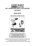
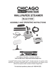
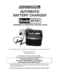
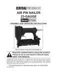
12 VOLT RECHARGEABLE
GREASE GUN
Model 92196
OPERATING INSTRUCTIONS
®
3491 Mission Oaks Blvd., Camarillo, CA 93011
Visit our Web site at: http://www.harborfreight.com
TO PREVENT SERIOUS INJURY,
READ AND UNDERSTAND ALL WARNINGS
AND INSTRUCTIONS BEFORE USE.
Copyright© 2004 by Harbor Freight Tools®. All rights reserved. No portion of this
manual or any artwork contained herein may be reproduced in any shape or form
without the express written consent of Harbor Freight Tools.
For technical questions, or replacement parts, please call 1-800-444-3353.
PRODUCT SPECIFICATIONS
Item
Description
Electrical Requirements
Maximum Operating Pressure
Grease Reservoir Capacity
Hose Size
Tube Dimensions
Housing Dimensions
Handle Dimensions
Trigger
LED Function Button
Weight
Charger Input Power: 120VAC / 60 Hz
Battery Output Power: 12VDC
Battery Capacity: 1300 MAH
Battery Charge Time: 1 Hour Quick Charge
6500 PSI
14.5 Ounces
30-1/2” Long x 0.386” Diameter
10-3/4” Long x 2.20” Diameter
7” L x 3” W x 1-1/2” H
7-1/2” L x 3” W (Overall)
Squeeze Type
“ON” / “OFF”
12.10 Pounds
UNPACKING
When unpacking, check to make sure all the parts shown on the Parts List on page 12
are included. If any parts are missing or broken, please call Harbor Freight Tools at the
number shown on the cover of this manual as soon as possible.
SAVE THIS MANUAL
You will need this manual for the safety warnings and precautions, assembly, operating,
inspection, maintenance and cleaning procedures, parts list and assembly diagram.
Keep your invoice with this manual. Write the invoice number on the inside of the front
cover. Keep this manual and invoice in a safe and dry place for future reference.
GENERAL SAFETY RULES
IMPORTANT SAFETY INSTRUCTIONS
WARNING!
READ AND UNDERSTAND ALL INSTRUCTIONS
Failure to follow all instructions listed below may result in
electric shock, fire, and/or serious injury.
SAVE THESE INSTRUCTIONS
WORK AREA
1.
Keep your work area clean and well lit. Cluttered benches and dark areas
invite accidents.
SKU 92196
For technical questions, please call 1-800-444-3353
PAGE 2
2.
Do not operate power tools in explosive atmospheres, such as in the
presence of flammable liquids, gases, or dust. Power tools create sparks
which may ignite the dust or fumes.
3.
Keep bystanders, children, and visitors away while operating a power tool.
Distractions can cause you to lose control.
ELECTRICAL SAFETY
1.
Avoid body contact with grounded surfaces such as pipes, radiators,
ranges, and refrigerators. There is an increased risk of electric shock if your
body is grounded.
2.
Do not expose power tools to rain or wet conditions. Water entering a power
tool will increase the risk of electric shock.
PERSONAL SAFETY
1.
Stay alert. Watch what you are doing, and use common sense when operating a power tool. Do not use a power tool while tired or under the influence of drugs, alcohol, or medication. A moment of inattention while operating power tools may result in serious personal injury.
2.
Dress properly. Do not wear loose clothing or jewelry. Contain long hair.
Keep your hair, clothing, and gloves away from moving parts. Loose
clothes, jewelry, or long hair can be caught in moving parts.
3.
Avoid accidental starting. Be sure the Switch (18) is released before plugging in. Carrying power tools with your finger on the Trigger, or plugging in
power tools with the Trigger depressed, invites accidents.
4.
Remove adjusting keys or wrenches before turning the power tool on. A
wrench or a key that is left attached to a rotating part of the power tool may result
in personal injury.
5.
Do not overreach. Keep proper footing and balance at all times. Proper
footing and balance enables better control of the power tool in unexpected
situations.
6.
Use safety equipment. Always wear ANSI approved safety glasses underneath
a full face safety shield. Dust mask, non-skid safety shoes, hard hat, or hearing
protection must be used for appropriate conditions.
SKU 92196
For technical questions, please call 1-800-444-3353
PAGE 3
TOOL USE AND CARE
1.
Do not force the tool. Use the correct tool for your application. The correct
tool will do the job better and safer at the rate for which it is designed.
2.
Do not use the power tool if the Switch (18) does not turn it on or off.
Any tool that cannot be controlled with the Switch is dangerous and must
be replaced.
3.
Disconnect the power tool from its Battery Pack (3) before making any
adjustments, changing accessories, or storing the tool. Such preventive
safety measures reduce the risk of starting the tool accidentally.
4.
Store idle tools out of reach of children and other untrained persons. Tools
are dangerous in the hands of untrained users.
5.
Maintain tools with care. Properly maintained tools are less likely to malfunction and are easier to control. Do not use a damaged tool. Tag damaged tools
“Do not use” until repaired.
6.
Check for misalignment or binding of moving parts, breakage of parts, and
any other condition that may affect the tool’s operation. If damaged, have
the tool serviced before using. Many accidents are caused by poorly maintained tools.
7.
Use only accessories that are recommended by the manufacturer for your
model. Accessories that may be suitable for one tool may become hazardous
when used on another tool.
SERVICE
1.
Tool service must be performed only by qualified repair personnel. Service
or maintenance performed by unqualified personnel could result in a risk of injury.
2.
When servicing a tool, use only identical replacement parts. Follow
instructions in the “Inspection, Maintenance, And Cleaning” section of this
manual. Use of unauthorized parts or failure to follow maintenance instructions
may create a risk of electric shock or injury.
SPECIFIC SAFETY RULES
1.
Maintain a safe working environment. Keep the work area well lit. Make sure
there is adequate surrounding workspace. Always keep the work area free of
SKU 92196
For technical questions, please call 1-800-444-3353
PAGE 4
obstructions, grease, oil, trash, and other debris. Do not use the Grease Gun in
areas near flammable chemicals, dusts, and vapors. Do not use this product in a
damp or wet location.
2.
Maintain labels and nameplates on this product. These carry important information. If unreadable or missing, contact Harbor Freight Tools for a replacement.
3.
When using the Grease Gun, always maintain a firm grip on the tool with
both hands.
4.
Do not use the Grease Gun or Charger (17) if it has been dropped, damaged, left outdoors, or immersed in liquid.
5.
To avoid electrical shock, do not handle the Charger (17), its Power Cord
Plug, or the Grease Gun with wet hands.
6.
Keep the outer body of the Grease Gun dry, clean, and free from oil and
grease.
7.
Always turn off the Grease Gun and unplug the Charger (17) from its
electrical outlet before changing accessories or performing any inspection, maintenance, or cleaning procedures.
8.
Avoid unintentional starting. Make sure you are prepared to begin work
before turning on the Grease Gun.
9.
To avoid electrical shock, do not pull or carry the Charger (17) by its Power
Cord.
10.
Never leave the Charger (17) unattended when it is plugged into an
electrical outlet. Make sure to unplug it from its electrical outlet before leaving.
11.
Proper Battery Pack Care: Battery Pack (3) leakage may occur under extreme
usage or temperature conditions. If Battery Pack fluid comes in contact with skin,
wash with soap and water and rinse with lemon juice and vinegar. If the fluid
comes into contact with the eyes, flush with water for several minutes and contact a doctor immediately. Never burn the Battery Pack, as it can explode in a
fire. Do not charge the Cordless Drill with a leaking Battery Pack. Contact local
solid waste authorities for instructions on correct disposal or recycling of the
Battery Pack.
12.
Always switch to a fresh Battery Pack (3) when tool performance begins to
diminish. Severe heat is most destructive to a Battery Pack. The more heat
SKU 92196
For technical questions, please call 1-800-444-3353
PAGE 5
generated, the faster the Battery Pack loses power. A Battery Pack that gets too
hot can be permanently damaged. Never over-discharge a Battery Pack by
using the tool while tool performance is decreasing. Never attempt to discharge
a tool’s Battery Pack by continuing to squeeze the tool Switch (18). When tool
performance begins to diminish, stop the tool, re-charge the Battery Pack, and
use the fresh Battery Pack for optimal performance.
13.
WARNING! People with pacemakers should consult their physician(s)
before using this product. Electromagnetic fields in close proximity to a heart
pacemaker could cause interference or failure of the pacemaker. In addition,
people with pacemakers should adhere to the following: Avoid operating power
tools alone. Don’t use a power tool with the power switch locked on. Properly
maintain and inspect all tools before use to avoid electrical shock.
14.
WARNING! The warnings, precautions, and instructions discussed in this
manual cannot cover all possible conditions and situations that may occur. The
operator must understand that common sense and caution are factors which
cannot be built into this product, but must be supplied by the operator.
SAVE THESE INSTRUCTIONS
TO CHARGE THE BATTERY PACK
NOTE: For additional information regarding the parts listed in the following pages, refer
to the Assembly Diagram on page 13.
1.
NOTE: The Battery Pack (3) requires charging. The first charge requires 1 hour
charge time prior to using the Grease Gun. (See Figure A, next page.)
2.
When the Battery Pack (3) requires re-charging, a 1 hour charge allows the tool
to operate at full power. Do not re-charge the Battery Pack longer than 1 hour,
as damage to the Battery Pack and/or Charger (17) will occur.
(See Figure A.)
3.
Insert the Battery Pack (3) into the Charging Socket of the Charger. Then, plug
the Charger (17) into the nearest 120 volt, grounded, electrical outlet.
(See Figure A.)
4.
The Green Light on the Charger (17) will automatically turn on. (See Figure A.)
SKU 92196
For technical questions, please call 1-800-444-3353
PAGE 6
5.
Depress the “SET” button on the Charger (17). The Green Light will automatically go out, and the Red Light will turn on indicating the Charger has switched to
the charge mode. (See Figure A.)
6.
In approximately 1 hour, when the Battery Pack (3) is fully charged, the Red Light
will automatically go out, and the Green Light will turn on. Remove the Battery
Pack from the Charger, and disconnect the Charger from its electrical outlet.
(See Figure A.)
7.
NOTE: The temperature of the Battery Pack (3) may increase during use and
shortly after use. The Battery Pack may not accept a full charge if it is charged
immediately after use. Allow the Battery Pack to cool to room temperature before
charging for best results. (See Figure A.)
CHARGER
(17)
(TOP VIEW)
BATTERY PACK
(3)
CHARGER
(17)
“SET” BUTTON
RED LIGHT
(CHARGE MODE)
GREEN LIGHT
(NON-CHARGE MODE)
FIGURE A
TO INSTALL A GREASE CARTRIDGE
1.
Pull back on the Follower Handle (19) until the Follower Rod (22) is fully extended. Then, turn the Follower Handle and latch the Follower Rod into the slot
on the end cap of the Grease Tube (2). (See Figure B, next page.)
2.
Unscrew and remove the Grease Tube (2) from the Pump Housing (6).
(See Figure B.)
3.
Remove the plastic cap from a grease cartridge (not included), and insert the
cartridge into the Grease Tube (2). (See Figure B.)
SKU 92196
For technical questions, please call 1-800-444-3353
PAGE 7
4.
Remove the pull tab from the grease cartridge. Then, screw the Grease Tube (2)
into the Pump Housing ( 6). (See Figure B.)
5.
Turn the Follower Handle (19) to release the Follower Rod (22) from the slot on
the end cap of the Grease Tube (2) to allow the Follower Rod (22) to move forward into the Grease Tube. (See Figure B.)
PUMP HOUSING
(6)
FOLLOWER ROD
(22)
FOLLOWER HANDLE
(19)
FILLER VALVE
(12)
GREASE TUBE
(2)
FIGURE B
TO FILL THE GREASE TUBE FROM A BULK CONTAINER
1.
Unscrew and remove the Grease Tube (2) from the Pump Housing (6).
(See Figure B.)
2.
Insert the open end of the Grease Tube (2) into the lubricant. Slowly pull the
Follower Handle (19) back while pushing the Grease Tube deeper into the lubricant to prevent air pockets from being pulled into the Grease Tube.
(See Figure B.)
3.
When the Follower Rod (22) is fully extended, turn the Follower Handle (19) and
latch the Follower Rod into the slot on the end cap of the Grease Tube (2).
(See Figure B.)
4.
Screw the Grease Tube (2) into the Pump Housing (6). (See Figure B.)
5.
Release the Follower Key (20) from the slot on the end cap of the Grease Tube
(2) to allow the Follower Rod (22) to move forward into the Grease Tube.
(See Figure B.)
6.
Clean off any excess grease off the outer body of the Grease Gun.
SKU 92196
For technical questions, please call 1-800-444-3353
PAGE 8
TO FILL THE GREASE GUN, USING A FILLER PUMP
1.
Pull back on the Follower Handle (19) until the Follower Rod (22) is fully extended. Then, turn the Follower Handle (19) and latch the Follower Rod into the
slot on the end cap of the Grease Tube (2). (See Figure B.)
2.
Attach the connector of the filler pump (not included) to the Filler Valve (12) on
the Grease Gun. (See Figure B.)
3.
Operate the filler pump to fill the Grease Tube (2). CAUTION! Make sure to
read and understand all safety warnings and instructions as outlined in the
owner’s manual of the filler pump.
4.
When the Follower Rod (22) automatically extends out from the rear of the
Grease Tube (2) about 8 inches, the Grease Tube is filled. Then, release the
Follower Key (20) from the slot on the end cap of the Grease Tube (2) to allow
the Follower Rod (22) to move forward into the Grease Tube. (See Figure B.)
TO ATTACH THE BATTERY PACK TO THE GREASE GUN
1.
Make sure the Switch (18) is in its “OFF” position. (See Figure C.)
2.
Depress the Lock Button on each side of the Battery Pack (3), and insert the
Battery Pack firmly into the bottom of the Right/Left Covers (1, 5) of the Grease
Gun. Then release pressure on the Lock Buttons, and check to make sure the
Battery Pack is locked in place. (See Figure C.)
SWITCH
(18)
RIGHT/LEFT COVERS
(1, 5)
LOCK BUTTON
BATTERY PACK
(3)
SKU 92196
For technical questions, please call 1-800-444-3353
FIGURE C
PAGE 9
TO EXPEL AIR POCKETS
1.
Release the Follower Rod (22) from the slot on the end cap of the Grease Tube
(2) to allow the Follower Rod to move forward into the Grease Tube
(See Figure B.)
2.
Push the Follower Handle (19) forward while depressing the Vent Valve (13).
(See Figure D.)
3.
Squeeze the Switch (18) several times to operate the Grease Gun until the
trapped air is expelled. Then, push the Follower Rod (22) all the way into the
Grease Tube (2). (See Figure D.)
VENT VALVE
(13)
SWITCH
COUPLER
(18)
(14)
GREASE TUBE
(2)
FOLLOWER ROD
(22)
FOLLOWER HANDLE (19)
FIGURE D
TO PRIME THE GREASE GUN
1.
Squeeze the Switch (18) until grease flows smoothly from the Coupler (14). If
necessary, depress the Vent Valve (13) to expel air pockets. (See Figure D.)
TO OPERATE THE GREASE GUN
1.
Attach a fully charged Battery Pack (3) to the Grease Gun. (See Figure C.)
SKU 92196
For technical questions, please call 1-800-444-3353
PAGE 10
2.
Always clean the grease zerk fitting carefully and completely with a clean cloth
prior to inserting the Grease Gun’s Coupler (14) onto the grease zerk fitting.
(See Figure D.)
3.
Insert the Coupler (14) fully onto the clean grease zerk fitting of the object you
are lubricating. (See Figure D.)
4.
With one hand, hold the Grease Tube (2) securely. With the other hand, squeeze
the Switch (18) several times or until a small amount of grease begins to flow
back out of the grease zerk fitting. (See Figure D.)
5.
Remove the Coupler (14) from the grease zerk fitting, and wipe any excess
grease from the exterior of the grease zerk fitting and Coupler. (See Figure D.)
6.
When finished, remove the Battery Pack (3) from the Grease Gun. Then, store
the Grease Gun in its Carrying Case (26) and in a clean, safe location out of
reach of children. (See Figure C.)
INSPECTION, MAINTENANCE, AND CLEANING
1.
WARNING! Make sure the Switch (18) is in its “OFF” position, and
unplug the Charger (17) from its electrical outlet before performing any
inspection, maintenance, or cleaning.
2.
BEFORE EACH USE, inspect the general condition of the Grease Gun. Check
for misalignment or binding of moving parts, cracked or broken parts, leaking
Battery Pack, damaged Hose (15), and any other condition that may affect its
safe operation. If abnormal noise or vibration occurs, have the problem corrected before further use.
Do not use damaged equipment.
3.
Battery Pack (3) precautions: Never burn Batteries, as they can explode in a
fire. Do not charge leaking Batteries. Only a qualified service technician should
perform maintenance on the Battery Pack. Contact local solid waste authorities
for instructions on correct disposal or recycling of the Battery Pack.
4.
DAILY: With a soft, dry cloth, remove all dirt, grease, and debris from the exterior of
the Grease Gun. Do not use solvents to clean the Grease Gun. Do not immerse
the Grease Gun in any liquids.
5.
When storing: Always remove the Battery Pack (3) from the Grease Gun. Keep
the Grease Gun and its accessories in a clean, dry location and out of childrens’
reach.
SKU 92196
For technical questions, please call 1-800-444-3353
PAGE 11
PLEASE READ THE FOLLOWING CAREFULLY
THE MANUFACTURER AND/OR DISTRIBUTOR HAS PROVIDED THE PARTS LIST AND ASSEMBLY
DIAGRAM IN THIS MANUAL AS A REFERENCE TOOL ONLY. NEITHER THE MANUFACTURER
OR DISTRIBUTOR MAKES ANY REPRESENTATION OR WARRANTY OF ANY KIND TO THE BUYER
THAT HE OR SHE IS QUALIFIED TO MAKE ANY REPAIRS TO THE PRODUCT, OR THAT HE OR
SHE IS QUALIFIED TO REPLACE ANY PARTS OF THE PRODUCT. IN FACT, THE MANUFACTURER
AND/OR DISTRIBUTOR EXPRESSLY STATES THAT ALL REPAIRS AND PARTS REPLACEMENTS
SHOULD BE UNDERTAKEN BY CERTIFIED AND LICENSED TECHNICIANS, AND NOT BY THE
BUYER. THE BUYER ASSUMES ALL RISK AND LIABILITY ARISING OUT OF HIS OR HER REPAIRS
TO THE ORIGINAL PRODUCT OR REPLACEMENT PARTS THERETO, OR ARISING OUT OF HIS
OR HER INSTALLATION OF REPLACEMENT PARTS THERETO.
PARTS LIST
Part #
1
2
3
4
5
6
7
8
9
10
11
12
13
Description
Right Cover
Grease Tube
Battery Pack
Motor Assembly
Left Cover
Pump Housing
Gear
Sleeve
Push Block
Pump Assy. Cover
Stopcock
Filler Valve
Vent Valve
Qty.
1
1
2
1
1
1
1
1
1
1
1
1
1
Part #
14
15
16
17
18
19
20
21
22
23
24
25
26
Description
Coupler
Hose
Seal Ring
Charger
Switch
Follower Handle
Follower Key
Spring
Follower Rod
Follower
Follower Seal
Screw
Carrying Case
Qty.
1
1
1
1
1
1
1
1
1
1
1
1
1
NOTE:
Some parts are listed and shown for illustration purposes only, and are not available
individually as replacement parts.
SKU 92196
For technical questions, please call 1-800-444-3353
PAGE 12
26: CARRYING CASE NOT SHOWN.
ASSEMBLY DIAGRAM
NOTE:
Some parts are listed and shown for illustration purposes only, and are not available
individually as replacement parts.
SKU 92196
For technical questions, please call 1-800-444-3353
PAGE 13