1
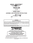
TRAILER WITH TAILGATE
(1,560 LB. WEIGHT CAPACITY)
Model 92174
Assembly And Operation Instructions
WARNING!
IMPORTANT INFORMATION
This trailer’s Hitch Coupler MUST be properly secured to the hitch ball of the towing vehicle. After assembly and
attachment, pull up and down on the Hitch Coupler to make sure the hitch ball is fitting snugly in the Hitch Coupler.
There must be no play between the hitch ball and Hitch Coupler. If there is play, tighten the Adjustment Nut
until no play is present. If the Adjustment Nut is too tight, the Handle will not lock. Carefully read and follow the
complete instructions in this manual BEFORE setup or use.
If the Coupler is not secured properly, the ball could come loose while the trailer is in motion, possibly causing property damage, SERIOUS PERSONAL INJURY, or DEATH.
Due to continuing improvements, actual product may differ slightly from the product described herein.
®
3491 Mission Oaks Blvd., Camarillo, CA 93011
Visit our website at: http://www.harborfreight.com
To prevent serious injury, read and understand
all warnings and instructions before use.
Copyright© 2004, 2007 by Harbor Freight Tools®. All rights reserved. No portion of
this manual or any artwork contained herein may be reproduced in any shape or
form without the express written consent of Harbor Freight Tools.
For technical questions or replacement parts, please call 1-800-444-3353.
Manual revised 07e
Contents
SPECIFICATIONS..................................................................................... 3
UNPACKING............................................................................................. 3
GENERAL SAFETY RULES..................................................................... 3
Work Area.............................................................................................................. 4
Equipment Use and Care...................................................................................... 4
Service................................................................................................................... 5
SPECIFIC PRODUCT WARNINGS AND PRECAUTIONS....................... 5
ASSEMBLY INSTRUCTIONS................................................................... 7
OPERATING INSTRUCTIONS................................................................. 14
Tire information............................................................................... 15
Tire Terminology Glossary.................................................................................. 15
Tire Markings........................................................................................................ 16
Tire Inflation and Load Limit............................................................................... 17
Tire care.............................................................................................. 18
Checking Tire Pressure....................................................................................... 18
Steps for Maintaining Proper Tire Pressure...................................................... 18
Tire Size................................................................................................................ 19
Tire Tread.............................................................................................................. 19
Tire Rotation......................................................................................................... 19
Tire Balance and Alignment................................................................................ 19
Tire Repair............................................................................................................ 19
Vehicle Load Limit............................................................................. 20
Steps for Determining Correct Load Limit......................................................... 20
INSPECTION, MAINTENANCE, AND CLEANING.................................. 21
PARTS LIST............................................................................................. 22
Hardware List....................................................................................................... 22
ASSEMBLY DIAGRAM............................................................................ 23
LIMITED 90 DAY WARRANTY................................................................. 24
REV 07e
SKU 92174
For technical questions, please call 1-800-444-3353.
Page SPECIFICATIONS
Maximum Weight Capacity
1,560 Pounds
Maximum Towing Speed
45 MPH
Overall Dimensions
112” L x 61-5/8” W x 26” H
Main Frame Dimensions
71-5/8” L x 49” W
Tailgate Dimensions
30-3/8” L x 43-1/4” W
Ground Clearance Dimensions
7-1/4” From Ground to Axle
Tires
Qty: 2 / DOT Approved
Maximum Permissible Inflation Pressure: 60 PSI
Size: 4.80-12
Hitch Type
Class II
Hitch Dimensions
9-3/8” L x 2-3/4”~3-3/4” W x 2”~4-1/2” H x 1/8” Thick
Tongue Dimensions
2” Square
Ball Size
2”
Light Voltage Requirements
12 Volts DC
Weight
246.5 Pounds
UNPACKING
When unpacking, make sure all the parts and hardware shown on the Parts List/
Hardware List are included. If any parts are missing or broken, please call Harbor Freight
Tools at the number shown on the cover of this manual as soon as possible.
Save This Manual
You will need this manual for the safety warnings and precautions, assembly, operating, inspection, maintenance and cleaning procedures, parts list and assembly diagram.
Keep your invoice with this manual. Write the invoice number on the inside of the front
cover. Keep this manual and invoice in a safe and dry place for future reference.
GENERAL SAFETY RULES
IMPORTANT SAFETY INSTRUCTIONS
WARNING!
Read and adhere to the following instructions. Failure to read and obey all of
the following instructions COMPLETELY will void the warranty and can result in
damage to the Trailer, property damage, or SERIOUS PERSONAL INJURY.
SAVE THESE INSTRUCTIONS.
REV 05k, 07h
SKU 92174
For technical questions, please call 1-800-444-3353.
Page Work Area
1.
Keep work area clean and dry. Cluttered, damp, or wet work areas invite injuries.
2.
Keep children away from work area. Do not allow children to play in, climb on
or ride in this product.
3.
Store idle equipment. When not in use, tools and equipment should be stored in
a dry location to inhibit rust. Always lock up tools and equipment, and keep out of
reach of children.
4.
Do not use this product if under the influence of alcohol or drugs. Read warning labels on prescriptions to determine if your judgement or reflexes are impaired
while taking drugs. If there is any doubt, do not attempt to use this product.
5.
Use eye protection. Wear ANSI-approved safety impact eye goggles when assembling this product. ANSI-approved safety impact eye goggles are available from
Harbor Freight Tools.
6.
Dress safely. Do not wear loose clothing or jewelry, as they can become caught
in moving parts. Wear a protective hair covering to prevent long hair from becoming caught in moving parts. If wearing a long-sleeve shirt, roll sleeves up above
elbows.
7.
Do not overreach. Keep proper footing and balance at all times to prevent tripping,
falling, back injury, etc.
8.
Industrial applications must follow OSHA requirements.
9.
Stay alert. Watch what you are doing at all times. Use common sense. Do not
use this product when you are tired or distracted from the job at hand.
Equipment Use and Care
1.
Check for damaged parts. Before using this product, carefully check that it will
operate properly and perform its intended function. Check for damaged parts and
any other conditions that may affect the operation of this product. Replace or repair
damaged or worn parts immediately.
2.
Replacement parts and accessories: When servicing, use only identical
replacement parts. Only use accessories intended for use with this product. Approved accessories are available from Harbor Freight Tools.
3.
Maintain this product with care. Keep this product clean and dry for better and
safer performance.
4.
Maintenance: For your safety, service and maintenance should be performed
regularly by a qualified technician.
SKU 92174
For technical questions, please call 1-800-444-3353.
Page 5.
Use the right equipment for the job. Do not attempt to force small equipment to
do the work of larger industrial equipment. There are certain applications for which
this product was designed. It will do the job better and more safely at the capacity
for which it was intended. Do not modify this product, and do not use this product
for a purpose for which it was not intended.
Service
1.
Equipment service must be performed only by qualified repair personnel.
Service or maintenance performed by unqualified personnel could result in a risk
of injury.
2.
When servicing equipment, use only identical replacement parts. Follow
instructions in the “Inspection, Maintenance, and Cleaning” section of this
manual. Use of unauthorized parts or failure to follow maintenance instructions
may create a risk of personal injury.
SPECIFIC PRODUCT WARNINGS AND PRECAUTIONS
1.
To avoid personal injury and/or property damage, do not exceed the Trailer’s
maximum weight capacity of 1,560 pounds.
2.
Before each use, always examine the Trailer for proper Tire air pressure (60
PSI), damaged tail lights, damaged side running lights, loose bolts and nuts,
structural cracks and bends, and any other condition that may affect its safe
operation. Do not use the Trailer even if minor damage appears.
3.
Never allow adults, children, or pets to ride in or play on the Trailer.
4.
Before each use, always attach the Safety Chain of the Trailer to the towing
vehicle. Make sure the Safety Chain is attached to the towing vehicle with the same
length for each side. Do not allow the Safety Chain to drag on the ground.
5.
Always check to make sure the payload being transported is properly and
safely secured in the Trailer. Load the Trailer evenly from side to side with 60%
of the load forward of the Axle.
6.
Prior to using the Trailer, make sure to read and understand all instructions and
safety precautions as outlined in the owner’s manual for the towing vehicle.
Make sure the towing vehicle is capable of towing the Trailer and its payload. Make
sure the hitch on the towing vehicle is capable of towing the Trailer and its payload.
The towing capacity of the hitch is typically stamped on the hitch drawbar.
7.
Make sure the Coupler and the vehicle’s ball hitch (not included) are of equal
mating size (2”) and are rated equal to or greater than the weight of the Trailer
and its payload.
SKU 92174
For technical questions, please call 1-800-444-3353.
Page 8.
Do not exceed 45 miles per hour when towing the Trailer. Excess speed is a
major cause of vehicle-trailer accidents. Poor road conditions, such as uneven, wet,
or unstable surfaces, will create further hazards if driven on too quickly. Reduce
speed to a safe level when driving in poor driving situations.
9.
The Tail Light Bulbs supplied with this Trailer are for a 12 volt DC electrical
system only. Do not attempt to power the Light Bulbs with any other type or voltage electrical current.
10.
Whenever possible, park the Trailer on a flat, level, paved, surface and chock
both Tires to keep the Trailer from accidently moving.
11.
CAUTION! Care must be taken when backing up the Trailer. Only back up
the Trailer on a straight path. If the Trailer is allowed to turn off the straight path
while backing up, the Trailer could jackknife, causing severe damage to the Trailer
and towing vehicle.
12.
Maintain labels and nameplates on the Trailer. These carry important information. If unreadable or missing, contact Harbor Freight Tools for a replacement.
13.
Reporting safety defects: If you believe your Trailer has a defect which could
cause a crash or could cause injury or death, you should immediately inform
the National Highway Traffic Safety Administration (NHTSA) in addition to
notifying the manufacturer, Changzhou Nanxiashu Tool Company. If NHTSA
receives similar complaints, it may open an investigation, and if it finds that a safety
defect exists in a group of vehicles, it may order a recall and remedy campaign.
However, NHTSA cannot become involved in individual problems between you, Harbor Freight Tools, or the manufacturer. To contact NHTSA, you may either call the
Auto Safety Hotline toll-free at 1-800-424-9393 or 202-366-0123 or write NHTSA,
U.S. Department, 400 7th Street SW NSA-11, Washington, D.C. 20590. You may
also obtain other information about motor vehicle safety from the Hotline.
14.
Trailer licensing notice: Some states may consider this Trailer a vehicle requiring registration, licensing, and titling. Check with your State Department
of Motor Vehicles for information and guidance on registering, licensing, and titling
the Trailer.
15.
WARNING: The warnings, precautions, and instructions discussed in this
manual cannot cover all possible conditions and situations that may occur.
The operator must understand that common sense and caution are factors, which
cannot be built into this product, but must be supplied by the operator.
SAVE THESE INSTRUCTIONS
SKU 92174
For technical questions, please call 1-800-444-3353.
Page ASSEMBLY INSTRUCTIONS
Note: For additional references to the parts listed on the following pages, refer to the Assembly Diagram.
A1
2
A20
2
6
A21
A2
2
2
1
A9
A20
A13
2
8
FIGURE A
1.
Attach the Tow Bar (A2) to the underside of the frame assembly, using two Bolts
(1), Lock Nuts (1), and Washers (1). (See Figure A.)
2.
Attach the ends of two Side Rails (A20) to the front end of the Trailer Frame (A1),
using four Bolts (2), Lock Nuts (2), and Washers (2). Then attach the remaining two
ends of the Side Rails to the Tow Bar (A2), using the “T” Plate (A21), four Bolts (2),
Lock Nuts (2), and Washers (2). Secure the Center with one Bolt (6), Lock Nut (6),
and Washer (6). (See Figure A.)
BOLT
3.
4.
Slide the Hitch Coupler (A9) onto the
end of the Tow Bar (A2), and align
the two mounting holes of the Hitch
Coupler with the two side mounting
holes of the Tow Bar.
(See Figures A and B.)
Locate the center link in the Safety
Chain (A13), and place the center
link inside the end of the Tow Bar
(A2). Insert a Bolt (8) horizontally
through the side/forward mounting hole of the Hitch Coupler (A9),
TOW BAR
(A2)
(8)
HITCH
COUPLER
(A9)
SAFETY CHAIN
(A13)
FIGURE B
REV 05k, 06b, 07e
SKU 92174
For technical questions, please call 1-800-444-3353.
Page through the center link in the Safety Chain, and through the Tow Bar. Firmly tighten
a Lock Nut (8) onto the Bolt (8) to secure the Safety Chain to the Tow Bar. Insert
another Bolt (8) through the side/rear mounting holes of the Hitch Coupler and Tow
Bar and secure with a Lock Nut (8). (See Figures A and B.)
With assistance, turn the Frame and Tow Bar assembly upside down.
5.
U-BOLT (3)
TRAILER
FRAME
(A1)
AXLE (A6)
TRAILER
SPRING (A8)
Cotter
Pin (7)
NUT (7)
Cotter
Pin (7)
NUT
(7)
BOLT (7)
SPRING PLATE
(3)
SPRING
HANGER
BOLT (7)
LOCK NUT and
Washer (3)
FIGURE C
6.
Place the two Trailer Springs (A8) in the spring hangers located on the underside of
the Trailer Frame (A1). Secure each Trailer Spring to the Trailer Frame, using two
Bolts (7), two Nuts (7), and two Cotter Pins (7). (See Figure C.)
7.
Place the Axle (A6) on top of the Trailer Springs (A8). Position a Spring Plate (3)
under each Trailer Spring. Place two U-Bolts (3) over each end of the Axle and
through each Spring Plate. Then secure the Axle to the Spring assembly, using four
Lock Nuts (3) and Spring Washers (3) for each end of the Axle. (See Figure C.)
REV 06b, 07e
SKU 92174
For technical questions, please call 1-800-444-3353.
Page WARNING! If the following procedure is not followed, it may result in wheel
locking and tire blowout, causing an automobile accident or road hazard.
Whenever a Hub (A7) on a new unit requires assembly (or a Hub is disassembled
for maintenance), the following procedures MUST be followed:
8.
a. Using a suitable solvent, thoroughly clean the Bearings (A7), Seal (A7), Cap
(A7), and the rest of the parts of the Hub assembly of all grease, dirt, metal
shavings, or any other foreign object. The parts must be cleaned even if they
are new or appear clean.
b. Allow all parts to dry completely.
c. Make sure your hands are clean and the bearing packer (not included) is also
clean.
d. Place fresh, clean bearing grease in the bearing packer.
e. With the grease-filled bearing packer in one hand and the Bearing (A7) in the
other, press the Bearing into the grease, forcing the grease inside the slots in
the Bearing. Continue doing this until every slot in the Bearing is completely
full of grease.
As you finish assembling the Hub, be careful not to get any dirt or debris on
any part of the assembly.
9.
COTTER PIN (A7)
AXLE (A6)
LUG NUT
(A7)
(LUBRICATE EVERY 90 DAYS)
GREASE FITTING
LUG NUT (A7)
HUB (A7)
TIRE & RIM (A10)
BEARINGS (A7)
FLAT WASHER (A7)
CASTLE NUT (A7)
CAP (A7)
FIGURE D
10.
Carefully slide the Hubs (A7) over the Spindles at each end of the Axle (A6). Insert
the Bearings (A7) and the Flat Washer (A7) on the Spindles. Screw a Castle Nut
SKU 92174
For technical questions, please call 1-800-444-3353.
Page (A7) tightly onto each Spindle. Then back the Castle Nuts off slightly so that the
Hubs can just move freely. (See Figure D, above.)
11.
Insert a Cotter Pin (A7) through the hole at the end of each Spindle of the Axle (A6)
and spread the Cotter pin. (See Figure D.)
12.
Fill the Caps (A7) with bearing grease. Then, press each Cap onto the Hubs (A7).
(See Figure D.)
13.
With assistance, turn the Trailer over so that it is facing correct side up.
LEFT TAIL LIGHT
(A15)
BOLT (2)
RIGHT TAIL LIGHT
(A16)
FIGURE E
TAIL LIGHT BOLT
BRACKET (2)
(A18)
SIDE
RUNNING LIGHT
(A19)
FENDER (A11)
FENDER
SUPPORT BAR
(A14)
BOLT (2)
14.
Attach the Tail Light Brackets (A18) to the right/rear and left/rear of the Trailer Frame
(A1), using two Bolts (2), Lock Nuts (2), and Washers (2) for each Tail Light Bracket.
(See Figure E.)
15.
Attach the Right Tail Light (A16) to the right side Tail Light Bracket (A18), using the
two Nuts that are factory pre-attached to the Right Tail Light. (See Figure E.)
16.
Attach the License Plate Bracket (A17) and Left Tail Light (A15) to the left side Tail
Light Bracket (A18), using the two Nuts that are factory pre-attached to the Left Tail
Light. (See Figure E.)
17.
Remove the Lens from a Side Running Light (A19). Insert the Wire Lead of the Side
Running Light through the center hole in the right/forward side of the Trailer Frame
(A1). Attach the Side Running Light to the Trailer Frame, using the two accessory
Self Tapping Screws. Then, reattach the Lens to the Side Running Light. Repeat
this procedure for the remaining Side Running Light on the left/forward side of the
Trailer Frame. (See Figure E.)
SKU 92174
For technical questions, please call 1-800-444-3353.
Page 10
18.
Attach a Fender (A11) to the right/middle section of the Trailer Frame (A1) and left/
middle section of the Trailer Frame, using one Fender Support Bar (A14), two Bolts
(2), Lock Nuts (2), and Washers (2) for each Fender. (See Figure E.)
19.
Place a Tire w/Rim (A10) on each Hub (A7). Secure the Tire w/Rims to the Hubs,
using four Lug Nuts (A7) per Tire. NOTE: Make sure to tighten (torque) the Lug
Nuts to at least 90 ft-lb. (See Figure D, page 9.)
TRAILER ENCLOSURE
(A12)
SUPPORT BAR
(A3)
REAR
CORNER
BRACE
(A4)
USE
BOLTS (2)
NUTS (2)
Cotter
PIN (5)
REAR
CORNER
BRACE
(A4)
REAR RAMP
(A5)
TRAILER FRAME
(A1)
PIN (4)
FIGURE F
20.
To attach the Trailer Enclosure (A12) to the Trailer Frame (A1), attach the lower portion
of the eight Support Bars (A3) to the front, left, and right sides of the Trailer Frame,
using one Bolt (2), Lock Nut (2), and Washer (2) for each Support Bar. Attach the
Trailer Enclosure to the top portion of each of the eight Support Bars. Attach the
lower portion of a Rear Corner Brace (A4) to the left/rear and right/ rear corners
of the Trailer Frame. Then, attach the Trailer Enclosure to the top portion of both
Corner Braces. (See Figure F.)
21.
To install the Rear Ramp (A5), insert the two Inner Hinges located at the bottom
of the Rear Ramp into the two Outer Hinge Slots located at the rear of the Trailer
Frame (A1). Insert the two Pins (4) through the two Outer Hinge Slots and Inner
Hinges. Then secure the Pins in place with the two Cotter Pins (5).
(See Figures F and G.)
REV 05c
SKU 92174
For technical questions, please call 1-800-444-3353.
Page 11
PIN LOCK
PIN LOCK
PIN (4)
TRAILER FRAME (A1)
INNER HINGE &
OUTER HINGE SLOT
22.
Cotter
PIN (5)
FIGURE G
Cotter
PIN (5)
PIN (4)
INNER HINGE &
OUTER HINGE SLOT
Raise the Rear Ramp (A5) to its up position. Then, lock the Rear Ramp in place
with the two Pin Locks. (See Figure G.)
REV 05c
SKU 92174
For technical questions, please call 1-800-444-3353.
Page 12
WHITE (GROUND)
WIRE CLIP
YELLOW
GREEN
WIRE FROM
SIDE RUNNING
LIGHT (A19)
WIRE FROM
SIDE RUNNING
LIGHT (A19)
BROWN
BROWN
RIGHT SIDE
TRAILER FRAME
(A1)
LEFT SIDE
TRAILER FRAME
(A1)
LEFT
TAIL LIGHT
(A15)
BROWN
RIGHT
TAIL LIGHT
(A16)
YELLOW
GREEN
BROWN
FIGURE H
23.
To install the Wiring Harness on the Trailer, use an accessory Self Tapping Screw
to attach the White Ground Wire located at the Plug end of the Wiring Harness to
the small mounting hole in the Tow-bar (A2). (See Figure H.)
24.
Leave about 18” of wire beyond the Hitch Coupler (A9), and run the Wiring Harness
along the inside of the Tow-bar (A2) to the front of the Trailer Frame (A1). Then, split
the Yellow/Brown Wires from the Green/Brown Wires. (See Figure H.)
25.
Run the Yellow/Brown Wires along the inside of the front of the Trailer Frame (A1)
to the Side Running Light (A16) located on the left/forward side of the Trailer Frame.
Then, run the Green/Brown Wires along the inside of the front of the Trailer Frame
to the other Side Running Light located on the right/forward side of the Trailer Frame.
(See Figure H.)
26.
Run the Green/Brown Wires to the Right Tail Light (A16). Strip the ends of the
Wires about 3/4”. Connect the Green Wire to the Red Wire of the Right Tail Light.
Then, connect the Brown Wire to the two Black Wires of the Right Tail Light.
(See Figure G.)
27.
NOTE: It is recommended that only a qualified technician perform the electrical
service that may be needed to enable your particular make/model vehicle to power
the Trailer’s 12 volt DC lighting system.
SKU 92174
For technical questions, please call 1-800-444-3353.
Page 13
OPERATING INSTRUCTIONS
TRIGGER
“R” PIN
HANDLE
SAFETY PIN
ADJUSTMENT
NUT
HITCH COUPLER
(A9)
HITCH BALL
(NOT INCLUDED)
SAFETY
CHAIN
(A13)
FIGURE I
1.
Only use a 2” ball hitch (not included) on the towing vehicle.
(See Figure I.)
2.
NOTE: To reduce friction between the hitch ball and Hitch Coupler (A9), apply a
layer of heavy weight grease over the hitch ball. (See Figure I.)
3.
Temporarily remove the “R” Pin and Safety Pin. Then, pull up on the Trigger and lift
up on the Handle. (See Figure I.)
4.
With assistance, place the Hitch Coupler (A9) over the vehicle’s hitch ball and push
down on the Handle until the Trigger locks in the slot. Pull up and down on the
Coupler to make sure the hitch ball is fitting snugly in the Coupler. There should be
no play between the hitch ball and Coupler. If there is play, tighten the Adjustment
Nut until no play is present. If the Adjustment Nut is too tight, the Handle will not
lock. WARNING! If the Hitch Coupler is not secured properly, the ball could
come loose while the Trailer is in motion, possibly causing property damage,
SERIOUS PERSONAL INJURY OR DEATH. (See Figure I.)
5.
Make sure to attach each side of the Safety Chain (A13) equally to the towing
vehicle’s rear bumper or frame. (See Figure I.)
6.
Connect the Tail Light Wiring Assembly to the towing vehicle’s 12 Volt DC system.
NOTE: Make sure to consult the operator’s manual of the towing vehicle for
proper connection instructions.
7.
CAUTION! Care must be taken when backing up the Trailer. Only back up
the Trailer on a straight path. If the Trailer is allowed to turn off the straight path
while backing up, the Trailer could jackknife, causing severe damage to the Trailer
and to the towing vehicle.
SKU 92174
For technical questions, please call 1-800-444-3353.
Page 14
8.
When towing the Trailer over long distances stop and check the tightness of all
connections, Side Running Lights (A19), and Tail Lights (A15, A16) at least every
100 miles.
9.
Carry emergency flares, and fire extinguisher, if required for operation in your
state.
10.
It is recommended to carry extra bulbs and fuses if towing the Trailer at night over
long distances.
Tire information
Tire Terminology Glossary
• Accessory weight means- the combined weight of automatic transmission, power steering, power
brakes, power windows, power seats, radio, and heater, to the extent that these items are available as
factory-installed equipment.
• Carcass means- the tire structure except for the tread which provides the major portion of the tire’s
capability to deflect in response to the vertical loads and tractive forces that the tire transmits from the
roadway to the non-pneumatic rim, the wheel center member, or the vehicle and which attaches to the
vehicle or attaches, either integrally or separably, to the wheel center member or non-pneumatic rim.
• Carcass separation means- the pulling away of the carcass from the non-pneumatic rim or wheel
center member.
• Chunking means- the breaking away of pieces of the carcass or tread.
• Cracking means- any parting within the carcass, tread, or any components that connect the tire to the
wheel center member.
• Curb weight means- the weight of a motor vehicle with standard equipment including the maximum
capacity of fuel, oil, and coolant, and, if so equipped, air conditioning and additional weight optional
engine.
• Load rating means- the maximum load a tire is rated to carry.
• Maximum loaded vehicle weight means- the sum of:
a. Curb weight;
b. Accessory weight;
c. Vehicle capacity weight; and
d. Production options weight.
• Maximum tire width means- the greater of either the linear distance between the exterior edges of the
carcass or the linear distance between the exterior edges of the tread, both being measured parallel to
the rolling axis of the tire.
• Normal occupant weight means- 68 kilograms times the number of occupants.
• Occupant distribution means- distribution of occupants in a vehicle.
REV 07e
SKU 92174
For technical questions, please call 1-800-444-3353.
Page 15
• Production options weight means- the combined weight of those installed regular production options
weighing over 2.3 kilograms in excess of those standard items which they replace, not previously considered in curb weight or accessory weight, including heavy duty brakes, ride levelers, roof rack, heavy
duty battery, and special trim.
• Tread means- that portion of the tire that comes in contact with the road.
• Tread separation means- pulling away of the tread from the carcass.
• Vehicle capacity weight means- the rated cargo and luggage load plus 68 kilograms times the vehicle’s
designated seating capacity.
• Vehicle maximum load on the tire means- that load on an individual tire that is determined by distributing to each axle its share of the maximum loaded vehicle weight and dividing by two.
• Vehicle normal load on the tire means- that load on an individual tire that is determined by distributing
to each axle its share of the curb weight, accessory weight, and normal occupant weight and dividing
by 2.
Tire Markings
Inner diameter
in inches
Section width
in inches
Load index and
Speed rating*
12
0-
71M
European tire
certificate*
4.8
X X XXX
Manufact
u
XX
TX
DO
U.S. DOT tire
identification
number
Xat XXl x plie
bs al
r XX l ide w
ex. loadplXies / s
la ea x
Lo
X P ad r
. R an
.
Tr ge _
ea _
d M
ar
Tr
a
i
Trailer
tire
r
e
Maximum
load rating
r
Maximum
permissible
inflation
pressure
. ld
o
PP..SR
.I. C Nylon
s
Tire ply
composition
and materials
used
*Information not required by U.S. DOT
• Section width- This number gives the width of the tire in inches. The larger the number, the wider the
tire. (The markings on the example tire diagram show 4.80. The markings on your tire may differ.)
• Inner diameter- This number gives the inner diameter of the tire in inches. This is also the rim diameter
in inches. (The markings on the example tire diagram show 12. The markings on your tire may differ.)
• U.S. DOT tire identification number- This begins with the letters “DOT” and indicates that the tire meets
all federal standards. The next two numbers or letters are the plant code where it was manufactured, and
the last four numbers represent the week and year that the tire was built. For example, the numbers 2107
mean the 21st week of 2007. Any other numbers used are marketing codes used at the manufacturer’s
discretion. This information is used to contact consumers if a tire defect requires a recall.
• Maximum Load Rating- This number indicates the maximum load in kilograms and pounds that can
be carried by the tire.
REV 07e
SKU 92174
For technical questions, please call 1-800-444-3353.
Page 16
Load Index Rating Codes
Code
Pounds
Code
Pounds
Code
Pounds
Code
Pounds
Code
Pounds
71
72
73
74
75
76
77
78
761
783
805
827
853
882
908
937
79
80
81
82
83
84
85
86
963
992
1,019
1,047
1,074
1,102
1,135
1,168
87
88
89
90
91
92
93
94
1,201
1,235
1,279
1,323
1,356
1,389
1,433
1,477
95
96
97
98
99
100
101
102
1,521
1,565
1,609
1,653
1,709
1,764
1,819
1,874
103
104
105
106
107
108
109
110
1,929
1,984
2,039
2,094
2,149
2,205
2,271
2,337
• Load index- This is a measurement of how much weight each tire can support. See chart above. (The
markings on the example tire diagram show 71. The markings on your tire may differ.) Note: You may
not find this information on all tires because it is not required by law.
• Speed Rating- The speed rating denotes the speed at
which a tire is designed to be driven for extended periods
of time. This does not indicate that the vehicle or rims
can safely reach or maintain that speed. These ratings
are listed to the right. (The markings on the example
tire diagram show M. The markings on your tire may
differ.) Note: You may not find this information on all tires
because it is not required by law.
Tire Speed Rating Codes
Code MPH
F
G
J
K
L
M
Code MPH
50
56
62
68
75
81
N
P
Q
R
S
T
87
94
100
106
112
118
Code MPH
U
H
V
Z
W
Y
124
130
149
149
168
186
• Tire Ply Composition and Materials Used- The number of plies indicates the number of layers of
rubber-coated fabric in the tire. In general, the greater the number of plies, the more weight a tire can
support. Tire manufacturers also must indicate the materials in the tire, which include steel, nylon,
polyester, and others.
• Maximum Permissible Inflation Pressure- This number is the greatest amount of air pressure that
should ever be put in the tire under normal driving conditions.
Tire Inflation and Load Limit
Tire and Loading Information Placard
Tire and loading information
The weight of cargo should never exceed 707 kg or 1560 lb.
n
TiO
ma
Or 1560 lb.
er’s
g inf kg or
din
e and
Tir
ht
weig
lOa
ed
exce
707
r
n
neve
aTiO
ld
infl
re
d Tire ssu
Psi
Pre
60
kPa,
414
o shou
of
carg
Tire
inal
Orig size
-12
4.80
The
COl
Own fOr
see ual nal .
man iTiO TiOn
add rma
infO
Original Tire
size
Cold Tire inflation
Pressure
4.80-12
414 kPa, 60 PSI
See owner’s
manual for
additional
information.
Tire and Loading Information Placard Location
The Tire and Loading Information Placard displays the cold tire inflation pressure
and the load limit for this vehicle. See the Tire Care section starting on the following page
for an explanation of tire pressure and see the Vehicle Load Limit section following that for
an explanation of load limit.
REV 07e
SKU 92174
For technical questions, please call 1-800-444-3353.
Page 17
Tire care
Checking Tire Pressure
Note: Underinflated tires can decrease handling, stopping performance, traction, tire life,
and load-carrying capability, in addition to causing other negative and hazardous
effects, including tire failure. Overinflated tires are at greater risk of an impact break,
where the tread and casing break when striking a hard edge, often opening a huge
gash across the tread. Incorrect inflation pressure also increases tires wear rate.
Therefore, it is important to keep tires inflated properly.
Check all tires’ pressure at least monthly, due to the following factors:
• Most tires naturally lose air gradually.
• Tires can suddenly lose air if the tire strikes a pothole, curb, or other object.
• It is usually not possible to determine underinflation of radial tires by visual inspection.
This vehicle has 60 PSI recommended cold tire inflation pressure. The term “cold”
in this manual does not refer to the temperature outside, but it refers to the fact that a tire
that has not been driven for a period is cooler (and therefore has lower pressure) than a
tire that has been driven on. Tires heat up while being driven on. To check (or fill to) a
tire’s cold inflation, the tire must have not been driven for more than a mile or two for at
least three hours. If you check a tires pressure when it is not “cold”, the pressure will appear higher than the actual cold tire inflation.
Steps for Maintaining Proper Tire Pressure
1.
Locate the recommended tire pressure on the vehicle’s tire information placard,
certification label, or in the owner’s manual. This trailer has 60 PSI recommended
cold tire inflation pressure.
2.
Measure and record the tire pressure of all tires.
3.
If the tire pressure is too high in any of the tires and the tires have not been driven
for at least three hours, slowly release air by gently pressing on the tire valve stem
with the edge of your tire gauge until you get to the correct pressure. If the vehicle
have been driven within the past three hours and the tire pressure is too high on any
tires, then recheck the pressure once the tires have been allowed to sit motionless
for at least three hours.
4.
If the tire pressure is too low, note the difference between the measured tire pressure and the correct tire pressure. These “missing” pounds of pressure are what
you will need to add.
5.
At a service station, add the missing pounds of air pressure to each tire that is
underinflated.
REV 07e
SKU 92174
For technical questions, please call 1-800-444-3353.
Page 18
6.
Check all the tires to make sure they have the same air pressure.
7.
If the tires’ pressure was not measured “cold”, then the pressure should be rechecked
with the tires cold as soon as possible.
Tire Size
To maintain safety, only purchase new tires of the same size as the original tires.
Look at the Tire and Loading Information Placard, the Specifications Chart in this manual,
or the sidewall of the tire being replaced. If you have any doubt about selecting the correct
size, consult a tire dealer.
Tire Tread
The tire tread provides traction that prevents your vehicle from slipping, especially
if the road is wet or icy. Tires are unsafe and should be replaced when the tread is worn
down to 1/16”. Measure tread depth using a tread depth indicator (not included).
Tire Rotation
Every 5,000 miles the left and right tires should be switched. This will cause the
tires to wear more evenly and last longer.
Tire Balance and Alignment
The tires need to be balanced to prevent vibration when driving. This involves attaching small weights to the rim to offset small differences in rim and tire weight. The tires
also need to be aligned properly. Alignment is the orientation of the tires to the road surface
and their being parallel. This helps the tires to wear evenly, and provide better traction.
Both tire balance and alignment require specialized equipment that is not provided with
this vehicle.
Tire Repair
To properly repair a punctured tire, the hole needs to be properly plugged and
patched from the inside of the tire. Tread punctures can be repaired if they are not too
large. Sidewall punctures should not be repaired, the tire needs to be replaced if the
sidewall is damaged. Tires should be removed from the rim to be inspected before being
plugged and patched. A qualified mechanic should remove the tire from the rim, perform
the repair, and remount the tire.
REV 07e
SKU 92174
For technical questions, please call 1-800-444-3353.
Page 19
Vehicle Load Limit
Steps for Determining Correct Load Limit
1.
Locate the statement “The weight of cargo should never exceed XXX pounds” on
your vehicle’s placard.
2.
That figure equals the available amount of cargo and luggage load capacity.
3.
Determine the combined weight of luggage and cargo being loaded on the vehicle.
That weight may not safely exceed the available cargo and luggage load capacity.
4.
If the trailer’s load exceeds the cargo and luggage load capacity, then the trailer
be unsafe resulting in hazardous effects, such as: Trailer’s tires will not be able to
maintain traction properly, and stopping distance will be increased significantly.
REV 07e
SKU 92174
For technical questions, please call 1-800-444-3353.
Page 20
INSPECTION, MAINTENANCE, AND CLEANING
1.
The following Chart serves as a basic guideline for scheduling your trailer maintenance. Maintenance may be different based on your local conditions, type of trailer,
and frequency of trailer use.
2.
CAUTION! All maintenance, service, or repairs listed in this manual are only to
be attempted by a qualified service technician.
Maintenance Chart
Maintenance Type
After
Before Before
After
Every 3 Every 6
First 50
Yearly
Use
Storage Storage
Months Months
Miles
Coupler
X
Ensure proper fit
X
Check Lubrication
X
X
Tongue Jack
X
Grease
Wheels and Hubs
Check lug nut tightness
X
X
Grease Bearings
X
X
X
X
X
Repack Bearings
X
Tires
Check Pressure (60 PSI) and
Visual Inspection
X
Check tread depth
X
X
X
X
X
Electrical
Check Tail and Brake Light
Operation
X
Check Electrical Ground
Wiring
X
X
REV 07e
SKU 92174
For technical questions, please call 1-800-444-3353.
Page 21
PLEASE READ THE FOLLOWING CAREFULLY
THE MANUFACTURER AND/OR DISTRIBUTOR HAS PROVIDED THE PARTS LIST AND
ASSEMBLY DIAGRAM IN THIS MANUAL AS A REFERENCE TOOL ONLY. NEITHER THE
MANUFACTURER OR DISTRIBUTOR MAKES ANY REPRESENTATION OR WARRANTY OF
ANY KIND TO THE BUYER THAT HE OR SHE IS QUALIFIED TO MAKE ANY REPAIRS TO THE
PRODUCT, OR THAT HE OR SHE IS QUALIFIED TO REPLACE ANY PARTS OF THE PRODUCT.
IN FACT, THE MANUFACTURER AND/OR DISTRIBUTOR EXPRESSLY STATES THAT ALL
REPAIRS AND PARTS REPLACEMENTS SHOULD BE UNDERTAKEN BY CERTIFIED AND
LICENSED TECHNICIANS, AND NOT BY THE BUYER. THE BUYER ASSUMES ALL RISK
AND LIABILITY ARISING OUT OF HIS OR HER REPAIRS TO THE ORIGINAL PRODUCT OR
REPLACEMENT PARTS THERETO, OR ARISING OUT OF HIS OR HER INSTALLATION OF
REPLACEMENT PARTS THERETO.
PARTS LIST
Part
Description
A1
B2
A3
A4
A5
A6
A7*
A8
B9
A10
A11
Trailer Frame
Tow Bar
Support Bar
Rear Corner Brace
Rear Ramp
Axle
Hub/Bearing/Seal/Cap
Trailer Spring
Hitch Coupler
Tire w/Rim
Fender
Qty.
Part
1
1
8
2
1
1
2
2
1
2
2
A12
A13
A14
A15
A16
A17
A18
A19
A20
A21
Description
Qty.
Trailer Enclosure
Safety Chain
Fender Support Bar
Left Tail Light
Right Tail Light
License Plate Bracket
Tail Light Bracket
Side Running Light
Side Rail
“T” Plate
1
1
2
1
1
1
2
2
2
1
*Includes Cotter Pin, Lug Nut, Flat Washer, and Castle Nut.
Hardware List
Part
1
2
3
Description
Bolt (M14x80)
Lock Nut (M14)
Washer (M14)
Bolt (M10x20)
Lock Nut (M10)
Washer (M10)
U-Bolt (F10)
Lock Nut (10)
Spring Washer
Spring Plate
Qty.
Part
2
sets
4
5
42
sets
6
4
8
8
2
7
8
Description
Pin (Ø12x95)
Cotter Pin (Ø3x25)
Bolt (M10x90)
Lock Nut (M10)
Washer (M10)
Bolt (M14x80)
Nut (M14)
Cotter Pin (Ø3x25)
Bolt (M12x75)
Lock Nut (M12)
Qty.
2
2
1
set
4
sets
2
sets
Note: Some parts and hardware are listed and shown for illustration purposes only, and
are not available individually as replacement parts or hardware.
REV 05k, 06b, 07e, 07f
SKU 92174
For technical questions, please call 1-800-444-3353.
Page 22
ASSEMBLY DIAGRAM
8
REV 06b, 07e
SKU 92174
For technical questions, please call 1-800-444-3353.
Page 23
LIMITED 90 DAY WARRANTY
Harbor Freight Tools Co. makes every effort to assure that its products meet high
quality and durability standards, and warrants to the original purchaser that this product
is free from defects in materials and workmanship for the period of 90 days from the date
of purchase. This warranty does not apply to damage due directly or indirectly, to misuse,
abuse, negligence or accidents, repairs or alterations outside our facilities, criminal activity,
improper installation, normal wear and tear, or to lack of maintenance. We shall in no event
be liable for death, injuries to persons or property, or for incidental, contingent, special
or consequential damages arising from the use of our product. Some states do not allow
the exclusion or limitation of incidental or consequential damages, so the above limitation
of exclusion may not apply to you. This warranty is expressly in lieu of all
other warranties, express or implied, including the warranties of
merchantability and fitness.
To take advantage of this warranty, the product or part must be returned to us with
transportation charges prepaid. Proof of purchase date and an explanation of the complaint must accompany the merchandise. If our inspection verifies the defect, we will either
repair or replace the product at our election or we may elect to refund the purchase price
if we cannot readily and quickly provide you with a replacement. We will return repaired
products at our expense, but if we determine there is no defect, or that the defect resulted
from causes not within the scope of our warranty, then you must bear the cost of returning
the product.
This warranty gives you specific legal rights and you may also have other rights
which vary from state to state.
3491 Mission Oaks Blvd. • PO Box 6009 • Camarillo, CA 93011 • (800) 444-3353
REV 07e
SKU 92174
For technical questions, please call 1-800-444-3353.
Page 24