1
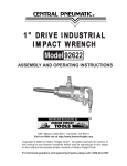
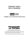
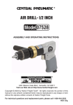
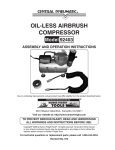
®
AIR DRILL- I/2 INCH
07528
ASSEMBLY AND OPERATING INSTRUCTIONS
3491 Mission Oaks Blvd., Camarillo, CA 93011
Visit our Web site at http://www.harborfreight.com
Copyright © 2004 by Harbor Freight Tools®. All rights reserved. No portion of this
manual or any artwork contained herein may be reproduced in any shape or form
without the express written consent of Harbor Freight Tools.
For technical questions and replacement parts, please call 1-800-444-3353
Specifications
Item
Chuck
Rated Air Pressure
Recommended Hose
Speed
Air Inlet
Weight
Description
½ inch, Jacobs type
90 PSI at 4 CFM
3/8 inch
550 RPM
¼” – 18 NPT
3.75 lbs.
Save this Manual
You will need the manual for the safety warnings and precautions, assembly
instructions, operating and maintenance procedures, parts list and diagram. Keep
your invoice with this manual. Write the invoice number on the inside of the front
cover. Keep the manual and invoice in a safe and dry place for future reference.
Safety Warnings and Precautions
WARNING: When using tool, basic safety precautions should always be followed to reduce the risk of personal injury and damage to equipment.
Read all instructions before using this tool!
1.
Disconnect air before servicing. Do not attempt to disassemble or service
tool with air hose attached.
2.
Use only specified operating air pressure. Recommended tool operating air
pressure is 90 PSI.
3.
Do not use combustible gases. Do not use combustible gases as a power
source, or use tool in areas where combustible gases are stored.
4.
Avoid possible kickback injury. Hold the tool with both hands during
operation so that your head and body are not injured by possible kickback of
the tool.
5.
Use care when transporting tool. Disconnect tool from air supply when
moving tool in the workplace. Carry tool only by the handle without drawing
the trigger.
6.
Keep work area clean. Cluttered areas invite injuries.
7.
Observe work area conditions. Do not use machines or power tools in
damp or wet locations. Don’t expose to rain. Keep work area well lighted.
SKU 07528
Page 2
8.
Keep children away. Children must never be allowed in the work area. Do
not let them handle machines, tools, or extension cords.
9.
Store idle equipment. When not in use, tools must be stored in a dry
location to inhibit rust. Always lock up tools and keep out of reach of children.
10. Do not force tool. It will do the job better and more safely at the rate for
which it was intended. Do not use inappropriate attachments in an attempt to
exceed the tool capacity.
11. Use the right tool for the job. Do not attempt to force a small tool or
attachment to do the work of a larger industrial tool. There are certain
applications for which this tool was designed. Do not modify this tool and do
not use this tool for a purpose for which it was not intended.
12. Dress properly. Do not wear loose clothing or jewelry as they can be caught
in moving parts. Protective, electrically nonconductive clothes and nonskid
footwear are recommended when working. Wear restrictive hair covering to
contain long hair.
13. Use eye and ear protection. Always wear ANSI approved impact safety
goggles. Wear an ANSI approved dust mask or respirator when working
around metal, wood, and chemical dusts and mists. Wear ear plugs.
14. Do not overreach. Keep proper footing and balance at all times. Do not
reach over or across running machines.
15. Maintain tools with care. Keep tools sharp and clean for better and safer
performance. Follow instructions for lubricating and changing accessories.
Inspect tool periodically and, if damaged, have them repaired by an
authorized technician. The handles must be kept clean, dry, and free from oil
and grease at all times.
16. Remove adjusting keys and wrenches. Check that keys and adjusting
wrenches are removed from the tool or machine work surface before
plugging it in.
17. Stay alert. Watch what you are doing, use common sense. Do not operate
any tool when you are tired.
18. Replacement parts and accessories. When servicing, use only identical
replacement parts. Use of any other parts will void the warranty. Only use
accessories intended for use with this tool. Approved accessories are
available from Harbor Freight Tools.
19. Maintenance. For your safety, service and maintenance should be
performed regularly by a qualified technician.
SKU 07528
Page 3
20. Check for damaged parts. Before using any tool, any part that appears
damaged should be carefully checked to determine that it will operate
properly and perform its intended function. Check for alignment and binding
of moving parts; any broken parts or mounting fixtures; and any other
condition that may affect proper operation. Any part that is damaged should
be properly repaired or replaced by a qualified technician. Do not use the tool
if any switch does not turn On and Off properly.
21. Do not operate tool if under the influence of alcohol or drugs. Read
warning labels on prescriptions to determine if your judgment or reflexes are
impaired while taking drugs. If there is any doubt, do not operate the tool.
Warning: The warnings, cautions, and instructions discussed in this instruction manual cannot cover all possible conditions and situations that may occur. It must be understood by the operator that common sense and caution
are factors which cannot be built into this product, but must be supplied by
the operator.
Warning: The brass components of this product contain lead, a chemical known
to the State of California to cause birth defects (or other reproductive harm).
(California Health & Safety Code 25249.5 et seq.)
Unpacking
When unpacking, check to make sure that the following parts are included. If any
parts are missing or broken, please call Harbor Freight Tools at the number on the
cover of this manual as soon as possible.
1/2 Inch Air Drill
(34)
(35)
(36)
Assembly
Air Connection
2.
Attach the Air Quick Coupler (not supplied) to the Air Inlet (13) fitting.
1.
If desired, for easy connection or removal, attach an Air Quick Coupler (not
supplied) to the air compressor hose.
3.
Tighten all couplings and fittings. See photos on the next page.
SKU 07528
Page 4
(13)
(30)
(8)
Oiler and Filter Connection
Dirt, water, and the lack of pneumatic tool oil are major causes for tool wear. Install
an optional oiler-filter, as illustrated below for better performance.
1.
Connect the air tool, air hoses, filter, and oiler to the Compressor Air Outlet
as illustrated below.
The filter and oiler (not supplied) are recommended but not mandatory for
operation.
If the filter and oiler are not used, connect the air hose directly to the 1/4 inch,
18 NPT connector located at the Air Inlet (13) fitting. Also, a few drops of
pneumatic tool oil must be added through the air line before each use.
Note: Use pipe thread seal or Teflon tape on all threaded connections.
Side Handle
1.
Slip the Brass Ring (35) over the Clamp Nut (30) and point the treads to
either the left or right side for the desired operation. See photo on the cover.
2.
Screw the Handle (34) onto the threads of the Brass Ring and tighten.
Operation
1.
Attach the desired bit (not supplied) to the Air Drill Chuck (32), making sure it
is locked in place with Chuck Key (36).
2.
Connect the compressor air hose (3/8”) to the Air Inlet (13) on the handle of
the housing (1).
SKU 07528
Page 5
3.
Set the (1.5 HP minimum) air compressor pressure regulator to 90 PSI.
If any air leaking, disconnect the air hose and repair the leak.
4.
Grip the Air Drill firmly with both hands and press down on the Trigger (8).
Caution: If the Air Drill will not turn, or if it stalls while drilling, do not raise the
outlet pressure of the air compressor. Do not continue with attempts to drill
until the problem is resolved.
5.
When you are finished drilling, turn the compressor off, then remove the hose
connection to the Air Drill.
Maintenance
1.
After each use, wipe the Air Drill with a clean cloth to remove any dirt and
grease buildup.
2.
To maintain tool life, always lubricate the air line by adding a few drops of
pneumatic tool oil to the air line before each use. Or, install the automatic
oiler-filter system as illustrated on page 5.
3.
Before each use, drain water out of the air compressor tank and
condensation from the air lines. Refer to the Air Compressor Operator’s
Manual.
Manual Tool Lubrication
1.
Disconnect the Air Drill from the air supply and turn it so the Air Inlet fitting is
facing upward.
2.
Hold the Trigger (8) in and place a few drops of pneumatic tool oil into the air
inlet (use SAE #10 weight oil if air tool oil is not available). Holding the Trigger
lever in helps circulate the oil in the air motor.
3.
Connect the Air Drill to the air supply and cover the Muffler Cover (11) with a
towel. Run for a few seconds. Excess oil with be blown out the Muffler Cover.
PLEASE READ THE FOLLOWING CAREFULLY
THE MANUFACTURER AND/OR DISTRIBUTOR HAS PROVIDED THE PARTS DIAGRAM
IN THIS MANUAL AS A REFERENCE TOOL ONLY. NEITHER THE MANUFACTURER NOR
DISTRIBUTOR MAKES ANY REPRESENTATION OR WARRANTY OF ANY KIND TO THE
BUYER THAT HE OR SHE IS QUALIFIED TO MAKE ANY REPAIRS TO THE PRODUCT OR
THAT HE OR SHE IS QUALIFIED TO REPLACE ANY PARTS OF THE PRODUCT. IN FACT,
THE MANUFACTURER AND/OR DISTRIBUTOR EXPRESSLY STATES THat ALL REPAIRS
AND PARTS REPLACEMENTS SHOULD BE UNDERTAKEN BY CERTIFIED AND
LICENSED TECHNICIANS AND NOT BY THE BUYER. THE BUYER ASSUMES ALL RISK
AND LIABILITY ARISING OUT OF HIS OR HER REPAIRS TO THE ORIGINAL PRODUCT
OR REPLACEMENT PARTS THERETO, OR ARISING OUT OF HIS OR HER INSTALLATION
OF REPLACEMENT PARTS THERETO.
SKU 07528
Page 6
Parts List
Item
1.
2.
3.
4.
5.
6.
7.
8.
9.
10.
11.
12.
13.
14.
15.
16.
17.
18.
Description
Housing
O-ring
O-ring
Valve Stem
O-ring
Bushing
Trigger Spring
Trigger
Trigger Screw
Pin
Muffler Cover
Screw
Air Inlet
Bearing
End Plate
Rotor
Rotor Blade
Cylinder
Qty
1
1
1
1
3
1
1
1
1
1
1
2
1
2
1
1
5
1
Item
19.
20.
21.
22.
23.
24.
25.
26.
27.
28.
29.
30.
31.
32.
33.
34.
35.
36.
Description
Pin
Front Plate
Washer
Gear
Gear
Pin
Gear Plate
Gear
Work Spindle
Thread Ring Gear
Bearing
Clamp Nut
Washer
Chuck
Chuck Screw
Handle
Brass Ring
Chuck Key
Qty
1
1
1
1
6
6
1
1
1
2
2
1
1
1
1
1
1
1
NOTE: Some parts are listed and shown for illustration purposes only and
are not available individually as replacement parts.
Assembly Drawing
SKU 07528
Page 7