1
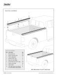
Universal pickup rack
Model 67498
Instructions and precautions
Visit our website at: http://www.harborfreight.com
Save these instructions. Read all
precautions and instructions.
Copyright© 2009 by Harbor Freight Tools®. All rights reserved. No portion of this document or any artwork contained herein
may be reproduced in any shape or form without the express written consent of Harbor Freight Tools. Diagrams within this
document may not be drawn proportionally. Due to continuing improvements, actual product may differ slightly from the
product described herein. Tools required for assembly and service may not be included.
For technical questions or replacement parts, please call 1-800-444-3353.
2.
Wear ANSI-approved safety goggles and heavyduty work gloves during assembly.
With Over-Cab Section: 1500 lb.
Without Over-Cab Section: 1200 lb.
3.
Keep assembly area clean and well lit.
4.
Unpacking
Keep bystanders out of the area during
assembly.
5.
Do not assemble when tired or when under the
influence of drugs, alcohol or medication.
Specifications
Weight Capacity
When unpacking, make sure that the
item is intact and undamaged. If any parts
are missing or broken, please call Harbor
Freight Tools at
1-800-444-3353 as soon as possible.
Important SAFETY Information
Assembly Precautions
1.
Assemble only according to these instructions.
Improper assembly can create hazards.
Use Precautions
1.
This product is not a toy. Do not allow children to
play with or near this item.
2.
Use as intended only.
3.
Inspect before every use; do not use if parts are
loose or damaged.
4.
Maintain product labels and nameplates. These
carry important safety information. If unreadable
or missing, contact Harbor Freight Tools for a
replacement.
Safety Warnings
1.
Do not exceed 1500 lb. capacity for
over-cab configuration, or 1200 lb.
capacity for bed-only configuration.
Be aware of dynamic loading!
Sudden movement may briefly
create excess load, causing product
failure. Vehicle structure may require
reinforcement to allow full capacity.
Do not overload vehicle. Consult
vehicle manufacturer.
in any direction, bouncing or shifting
of load.
12. Along with the weight capacity of this
Pickup Rack, be aware of the weight
bearing capabilities of the vehicle,
suspension, and tires.
13. Driving techniques must take into
consideration the change in center of
gravity, and the different driving and
handling characteristics when the
Pickup Rack is loaded.
2.
Wear ANSI-approved goggles and
heavy-duty work gloves during
assembly.
14. Trucks with bedliners may have to
be modified to allow the use of the
J-Bolts.
3.
Use as intended only.
4.
Verify that installation surfaces have
no hidden wires or components
before drilling.
15. Loaded Pickup Rack is not
recommended for unimproved or
poorly maintained roads.
5.
Secure load before use. Follow traffic
regulations for loads transported.
6.
Inspect before every use; do not use
if parts loose or damaged.
7.
Install and use according to manual
instructions.
8.
Do not modify this product or use it
for any use other than its intended
purpose.
9.
Check to see if the vehicle
manufacturer requires a reinforcing
kit for this installation.
10. In the event that this rack is to be
mounted on the truck bed:
a.All floor mounting bolts near gas
tanks must be installed from
underneath to avoid tank rupture in
the event of a collision.
16. If this rack cannot be installed
according to instruction, do not use.
17. Loads extending beyond the back of
the truck must have a red flag (day)
or red light (night). Check local DOT
regulations.
18. Avoid having material protruding
beyond the sides which may injure a
passerby.
19. After assembly and mounting on
vehicle, double check all connections
to make sure all fasteners are
properly and securely tightened.
20. Be aware of cross winds when
traveling with items placed on the
rack.
b.Inspect underneath truck bed for fuel
lines, electrical wiring, brake lines,
etc. before drilling.
11. All loads placed on this Pickup Rack
must be secured against movement
Page 2
For technical questions, please call 1-800-444-3353.
SKU 67498
through the top of the rim. You will need
to cut holes in the side of a liner if the
truck bed has a liner, or if the side of the
truck bed is solid, without an inner rim.
Assembly Instructions
Read the entire Important
Safety Information
section at the beginning of this
document including all text under
subheadings therein before set up
or use of this product.
Front Crossbar (7)
Drilled and Bolted Configuration
Post B (13)
Bolt (17) & Washer (20) &
Washer (20)
Nut (26)
(not shown)
Assembled Rail
(Unused
J-Bolt Slots)
Figure 1
Post B (13)
Holes drilled in
Bed Liner
Post A (12)
This Rack is designed to fit over a standard
or short bed pickup truck, with or without the
section over the vehicle cab. You can adjust
the location of the Posts along the Assembled
Rail to fit your vehicle.
Figure 3
Nut (26),
Washer (23),
Washer (20)
Bed Liner
To mount the Rack by bolting it to the
top of the truck bed rim, you will need
to drill holes in the top of the Pickup rim
to attach the Posts (12/13). If the truck
bed has a liner, or the side of the truck
bed is solid, you will also need to cut 2”
holes in the side so you have access to
the bottom of the Bolts (17) to add the
Washers (20) and Nuts (26).
J-Bolt Configuration
(Side View)
Post A or B (12/13)
Bolt (17) &
Washer (20)
Post Base
CAUTION: Do not drill any holes until you
have fully assembled the rack and
placed it on the truck bed to double
check the hole placement.
J-Bolt Slot
Preparation
1.
J-Bolt (15)
Pickup Side Rim
Side of Pickup Bed
Use the J-Bolt (15) configuration as
shown in Figure 2 for bolting the Rack
to the truck bed without drilling holes
SKU 67498
Note: Some parts are similar, but not
identical, such as Post A (12) and Post B
(13). Use the Assembly Diagram to help
identify all parts.
2.
Figure 2
Lay out and identify all parts.
Determine approximately where to
attach the Posts (12/13) to the rim of
the truck bed without interfering with
other structures or hidden components
within the truck bed. Record the distance
For technical questions, please call 1-800-444-3353.
Page 3
between posts and mark the location for
the bolts on the truck bed.
and the smaller bar sits on top of the
flange at the top of the Posts. Position
the Rail so the vertical supports are not
in the way of attaching the Posts.
Attaching the Side Rails Together
Bolt (18)
Bolt (19)
Washers (22)
Nut (25)
Left
Middle
Rail (4)
Washers (22)
Figure 4
Vertical Supports
Nut (25)
Left
Back
Rail (6)
Figure 6
Slide the Left Middle Rail (4) into the Left
Back Rail (6) and secure the smaller bar
sections together with the Bolt (18), two
Washers (22), and a Nut (25), and the
larger bar sections together with the Bolt
(19), two Washers (22), and a Nut (25).
Note: The vertical supports on the Rail
sections should be positioned so they
are on the inside of the framework. The
Posts can be positioned anywhere along
the Rails between the vertical supports.
2.
Working with one Post at a time, straddle
the large bottom bar of the Rail with the
Crossbeam Sockets (14), aligning the
holes on the Crossbeam Sockets with
the holes in the Post.
3.
Secure the Crossbeam to the large
bar and Post with two Bolts (19), four
Washers (22) and two Nuts (25).
4.
Secure the small top bar to the top
flange of the Post with the U-Bolt (16),
two Washers (21) and two Nuts (24).
5.
Repeat steps 1-4 above for the other
assembled Rail section and remaining
Posts.
6.
Double check the distances between the
Posts and adjust their distances so they
will fit on the truck bed as determined in
step 2 under “Preparation”.
Attach the Right Middle and Right Back
Rails (3 & 5) in the same manner.
Attaching the Posts to the Side Rails
Small Top Bar
Large Bar
Bolt (19),
Washer (22)
& Nut (25)
Assembled Rail
U-Bolt (16)
Washer (21)
& Nut (24)
Crossbar (8)
Crossbeam Socket (14)
Post (12/13)
Figure 5
1.
Lay one Post A and one Post B on the
ground at the approximate distance apart
as in step 2 under “Preparation” and lay
one assembled Rail section over the
Posts, so the large lower bar fits into the
cupped section near the top of the Posts
Page 4
Optional Construction
with Bar over Cab
This unit can be assembled as a smaller
Rack by omitting the pieces positioned over
the Truck Cab, or it can be assembled as
For technical questions, please call 1-800-444-3353.
SKU 67498
shown on the manual cover, with the extra
section over the truck cab. If assembling in
the smaller configuration, skip this section
and go to “Completing the Rack” below. If
assembling with the over-cab section, attach
the Left Front and Right Front Rails (2 & 1) to
the assembled rail sections using the same
hardware as used for attaching the other side
rail sections.
Rack is ready to secure. Secure in place
through the base of the Posts with the
Hex Bolts (17), Washers (20), and Nuts
(26), or tighten the Nuts on the J-Bolts,
as needed for your vehicle.
4.
Note: The Rack supports up to 1500 lbs in the
over-cab configuration and up to 1200
lbs in the smaller configuration.
Adjust and tighten the Hex Bolts
holding the Crossbars. Check that all
connections are secure and all bolts are
tight.
5.
Insert the Large and Small End Caps
(10, 11) into the ends of the bars and
posts.
Completing the Rack
Note: You may want to shorten the length of
the Back Rails by sawing off the ends
before inserting the End Caps.
1.
2.
Working with one assembled section,
slide the Crossbars (8 & 9) into the
Crossbeam Sockets (14). If making the
over-cab construction also slide the front
Crossbar (7) into the Front Rail (1 or 2)
and tighten in place with the Hex Bolts
(17).
Slide the other ends of the Crossbars
into the other assembled section, insert
the Hex Bolts, but do not fully tighten so
you can adjust the width of the Rack, if
needed.
Note: If assembling with the J-Bolts (15),
loosely pre-assemble the J-Bolts (15),
Nuts (26) and Washers (20/23) through
the J-Bolt Slots in the Post bases.
Operation
1.
Secure all loads in place.
2.
Be aware of dynamic loading. Dropping,
swinging or bouncing load may briefly
create excess load causing product
failure.
3.
Cargo protruding beyond the back of the
truck and Rack must be identified by a
red flag by day and a red light by night.
Check local DOT regulations.
Note: If attaching to a truck bed with a liner,
use a Cargo Bar (sold separately - SKU
66172) to press the liner up against the
truck bed sides to get a snug fit on the
truck bed and liner.
Attaching the Rack to the Truck
1.
With a helper, lift the assembled Rack
and position on the vehicle.
2.
Drill holes in the truck bed and/or liner as
needed.
3.
If using the J-Bolts, hook them under
the Pickup Side Rim. Adjust the width
or post positions as needed until the
SKU 67498
For technical questions, please call 1-800-444-3353.
Page 5
PLEASE READ THE FOLLOWING CAREFULLY
The manufacturer and/or distributor has provided the parts list and assembly
diagram in this manual as a reference tool only. Neither the manufacturer or
distributor makes any representation or warranty of any kind to the buyer that he
or she is qualified to make any repairs to the product, or that he or she is qualified
to replace any parts of the product. In fact, the manufacturer and/or distributor
expressly states that all repairs and parts replacements should be undertaken by
certified and licensed technicians, and not by the buyer. The buyer assumes all risk
and liability arising out of his or her repairs to the original product or replacement
parts thereto, or arising out of his or her installation of replacement parts thereto.
Part
1
2
3
4
5
6
7
8
9
10
11
12
13
Description
Right Front Rail
Left Front Rail
Right Middle Rail
Left Middle Rail
Right Back Rail
Left Back Rail
Front Crossbar
Middle Crossbar
Rear Crossbar
Small End Cap
Large End Cap
Post A
Post B
Qty
1
1
1
1
1
1
1
1
1
6
8
2
2
Part
14
15
16
17
18
19
20
21
22
23
24
25
26
Description
Qty
Crossbeam Sockets
J-Bolt
U-Bolt
Hex Bolt M16 x 30
Bolt M10 x 40
Bolt M10 x 70
Washer 16
Washer 8
Washer 10
Spring Washer 16
Nut M8
Nut M10
Nut M16
4
8
4
14
4
12
24
8
32
8
8
16
16
Record Product’s Serial Number Here:
Note: If product has no serial number, record month and year of purchase instead.
Note: Some parts are listed and shown for illustration purposes only, and are not available
individually as replacement parts.
Page 6
For technical questions, please call 1-800-444-3353.
SKU 67498
Parts List & ASSEMBLY DIAGRAM
Note: Add end caps only to
open pipe ends of finished
configuration. You will not
need to add end caps
to Parts #3 and #4 if
constructing the over-cab
configuration.
SKU 67498
For technical questions, please call 1-800-444-3353.
Page 7
LIMITED 90 DAY WARRANTY
Harbor Freight Tools Co. makes every effort to assure that its products meet high quality
and durability standards, and warrants to the original purchaser that this product is free from
defects in materials and workmanship for the period of 90 days from the date of purchase. This
warranty does not apply to damage due directly or indirectly, to misuse, abuse, negligence or
accidents, repairs or alterations outside our facilities, criminal activity, improper installation,
normal wear and tear, or to lack of maintenance. We shall in no event be liable for death,
injuries to persons or property, or for incidental, contingent, special or consequential damages
arising from the use of our product. Some states do not allow the exclusion or limitation of
incidental or consequential damages, so the above limitation of exclusion may not apply to
you. This warranty is expressly in lieu of all other warranties, express
or implied, including the warranties of merchantability and fitness.
To take advantage of this warranty, the product or part must be returned to us with
transportation charges prepaid. Proof of purchase date and an explanation of the complaint
must accompany the merchandise. If our inspection verifies the defect, we will either repair or
replace the product at our election or we may elect to refund the purchase price if we cannot
readily and quickly provide you with a replacement. We will return repaired products at our
expense, but if we determine there is no defect, or that the defect resulted from causes not
within the scope of our warranty, then you must bear the cost of returning the product.
This warranty gives you specific legal rights and you may also have other rights which
vary from state to state.
3491 Mission Oaks Blvd. • PO Box 6009 • Camarillo, CA 93011 • (800) 444-3353
Page 8
For technical questions, please call 1-800-444-3353.
SKU 67498